Valor 1595CFKV2 Le manuel du propriétaire
- Catégorie
- Cheminées
- Taper
- Le manuel du propriétaire

1
Note: This kit must be installed or serviced
by a qualified installer, service agency
or gas supplier. These instructions are
to be used in conjunction with the main
installation instructions for the above
listed models.
GROUNDING: The power supply for this accessory must be installed and grounded in
accordance with local codes, or in the absence of local codes, with the current Canadian
Electrical Code CSA C22.1. or in the USA the National Electrical Code ANSI/NFPA70 latest
edition.
Description of System
The models 1500, 1700 and 1800 fireplaces have been
designed to accommodate the installation of an optional
150CFM air circulation fan. The fan is designed to boost
the natural convection through the heater; this may be
a desirable feature dependent on the fireplace location
and room layout.
It is preferable to install the circulating fan before
completing the heater installation although it may
also be retrofitted at a later date provided the power re-
ceptacle has been prewired within the fireplace casing.
Retrofitting the fan after the fireplace installation is com-
pleted will require disconnecting the gas and removing
the burner module and gas train from the fireplace.
The fan is designed for automatic operation to come ON
and OFF when the burner comes ON and turns OFF. The
fan speed can be controlled from the remote control
handset. There are four speeds available.
The fan, if turned ON, will start approximately 4 minutes
after lighting the appliance and will continue to run for
approximately 10 minutes after the burner is shut off.
The fan will operate at the speed last selected by the
user.
Future servicing or replacement of the fan may be done
through the window aperture of the fireplace without
needing to remove the fireplace from the wall cavity.
4007879-01
© 2019, Miles Industries Ltd. All rights reserved.
Electrical Requirements
This optional fan kit connects to a control module (sold
separately) to be mounted within the fireplace casing.
The fan electrical requirements are 120 Volts, 1 phase,
60 Hz. Full load current of less than 1 amp.
1595CFKV2 CIRCULATING FAN KIT
Use with Valor models 1500K, 1700K and 1800K Linear Fireplaces
INSTALLATION & OPERATING INSTRUCTIONS
Linear
WARNING
If these instructions are not followed
exactly, a fire or explosion may result
causing property damage, personal
injury or loss of life.
NOTICE
A control module GV60VM—V-Module kit
(sold separately) is required to provide
power and speed control to the fan. The
V-Module plugs into a receptacle located
within the fireplace. Ensure power is
provided to the receptacle. See Electrical
Wiring section in fireplace installation
manual for details.
Please leave this manual with the homeowner.

2
Considerations
We highly recommend installing this fan (blower) kit to
the appliance before completing the installation of the
appliance otherwise the gas line must be disconnected
and the burner module removed from the firebox to
gain access to the blower area.
If installing this fan after the fireplace installation has
been completed, remove the following components
using the fireplace installation manuals provided with
the fireplace:
• Disconnect the gas line from the appliance at the
appliance valve.
• Barrier screen, trim side doors, trim plinth, plinth
support, window, fuel bed, fuel bed platform.
NOTE: Electrical wiring should be already installed
inside the appliance case. An electrical supply to the
control module is required to power this optional fan.
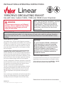
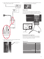
Installation Components Required
1595CFKV2—Circulating Fan Kit, containing:
• Fan unit (motor and housing)
• Fan mounting plate
• Thermal switch
• Power cable with Molex connector
• Wiring diagram label
• Sheet metal screws (2)
GV60VM—V-Module Kit (sold separately),
containing:
• V-Module - relay box
• Receiver to relay cable
• Power cord assembly with plug
BLOWER BLOWER
JUNCTION BOX
WITHIN FIREPLACE
GND
RECEIVER TO RELAY CABLE #4002531 SUPPLIED
SEPARATELY WITH FAN CONTROL MODULE
3-PIN MOLEX
POWER CORD,
37” LONG
#4007877
POWER CORD ASSEMBLY
#4006350 SUPPLIED
SEPARATELY WITH FAN
CONTROL MODULE
REMOTE CONTROL
RECEIVER
SHIPPED WITH
FIREPLACE
NOTE - ALL WIRING IS SPECIFIC TO THIS KIT
AND SHOULD ONY BE REPLACED WITH
ORIGINAL EQUIPMENT WIRING FROM THE
MANUFACTURER.
FAN CONTROL MODULE
#4002530
(SUPPLIED SEPARATELY)
MOLEX
CONNECTORS
CIRCULATING FAN KIT
120 VAC, 60HZ, LESS THAN 1 AMP
MANUFACTURED BY
MILES INDUSTRIES LTD
NORTH VANCOUVER, CANADA
4007878-01
MODEL 1595CFKV2
THERMAL SWITCH
GROUND WIRE, BLOWER HOUSING
TO STUD ON MOUNTING PLATE
Fan unit
Fan mounting plate
Thermal switch
Power cable
Sheet metal
screws (2)
Wiring diagram
and label
1595CFKV2
GV60VM (sold separately)
V-Module
relay box
Receiver to
relay cable
Power cord assembly

3
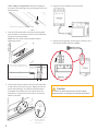
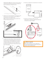
Remove wire from
switch and connect
directly to motor for
testing
Test fan
It may be desireable to test the fan operation before
reassembling the burner module and completing the
fireplace installation.
To test the fan operation the thermal switch can be
temporarily bypassed by connecting the power cord
lead directly to the fan motor (see diagram). Be careful
with wire terminals on motor, they are fragile. Unplug
the power cord from the control module before
bypassing the thermal switch. Following instructions
below, confirm fan operation with the thermal switch
bypassed then reconnect thermal switch.
Note: If desirable, the thermal switch may be left
permanently bypassed; however the fan may continue
to run when the burner shuts off but the control knob
has not yet rotated all the way down.
Operation with Valor 10 Remote Control
To operate the fan, press the button on the remote
handset; the fan icon flashes on the display. Press
the and buttons to set the fan speed. No bar
showing means the fan is OFF. Press the button to
confirm the setting or wait. The fan icon and number
of bars will show when the remote is in other modes
to confirm the fan status. There may be a delay if the
fireplace has just been turned on.
Note: When the heater is operated at lower settings,
the fan may cycle off and on repeatedly as the thermal
switch temperature cannot be maintained due to the
operation of the fan.
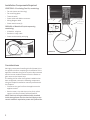
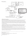
Insert fan and rotate into position
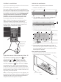
Install fan
To gain access to the fan area
1. Detach the burner (3 screws).
2. Slide the burner right to disengage it from the orifice
and lift it straight out of the firebox.
3. Remove the middle burner mount (2 screws).
4. Detach the burner module plate (10 screws).
5. Rotate the rear edge of the burner module upwards
and remove the module plate from the firebox
being careful not to damage the pipes and other
parts attached underneath the plate.
To install the fan
1. Insert the fan through the opening in the floor of the
firebox and rotate into position.
Middle
burner
mount
Burner module plate

4
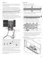
4. Plug the control module into the receiver.
5. Plug the 3-prong power cord’s molex connector into
the control module marked “POWER”.
1700 / 1800 J or K appliances: Remove the plate to
the right of the opening to access fixing points for the
fan (4 screws).
2. Line up the slotted holes in the fan mounting plate
with the holes in the base of the liner box and fasten
using two screws provided.
Note: Push fan as far back as possible before
tightening screws.
3. The thermal switch bracket is fixed to the underside
of the firebox floor from the top. Slightly loosen the
two screws holding it and slide the thermal switch
in between the bracket and the underside of the
firebox floor. Tighten the two screws to secure the
switch in position.
Slide thermal switch
between bracket
and underside of
firebox floor
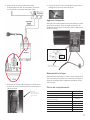
Remove fan fixing access plate (4 screws)
1700 / 1800 J or K appliances:
secure fan through access hole
Bottom of fireplace transparent for clarity
Caution
DO NOT run wires over the top of the firebox.
Route the wire so they do not contact the firebox.

5
BLOWER BLOWER
JUNCTION BOX
WITHIN FIREPLACE
GND
3-PIN MOLEX
POWER CORD,
37” LONG
#4007877
POWER CORD ASSEMBLY
#4006350 SUPPLIED
SEPARATELY WITH FAN
CONTROL MODULE
NOTE - ALL WIRING IS SPECIFIC TO THIS KIT
AND SHOULD ONY BE REPLACED WITH
ORIGINAL EQUIPMENT WIRING FROM THE
MANUFACTURER.
FAN CONTROL MODULE
#4002530
(SUPPLIED SEPARATELY)
MOLEX
CONNECTORS
CIRCULATING FAN KIT
120 VAC, 60HZ, LESS THAN 1 AMP
MANUFACTURED BY
MILES INDUSTRIES LTD
NORTH VANCOUVER, CANADA
4007878-01
MODEL 1595CFKV2
THERMAL SWITCH
GROUND WIRE, BLOWER HOUSING
TO STUD ON MOUNTING PLATE
Apply label to
base next to fan
Junction box in
lower right corner
of liner box
Description Part Numbers
Blower 4000537
Fan Mounting Bracket 4003053
3-pin Molex Power cord, 37” long
4007877
Thermal Switch 4003065
Cable, Switch to Motor, 10” 4003067
Ground cable, eyelet each end 4003068
Clamp Self Adhesive 4000536
Schematic label 1595CFKV2 4007878
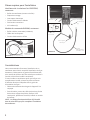
6. Plug the fan power cord molex connector into the
control module marked “FAN”.
7. Plug the 3-prong power cord into receptacle at the
right into the fireplace case.
8. Use the self-adhesive wire clamp provided to secure
the cables to the base of the fireplace.
Apply label
Clean the area of sheet metal liner box base adjacent
to the fan, peel the self-adhesive backing from the label
provided with the kit and apply the label to the base.
Reassemble the appliance
Reassemble the unit in reverse order and continue
with the heater installation following the installation
instructions supplied with the heater.
Spares List

6
Limited warranty policy
Miles Industries Ltd. warrants all components of the model 1595CFKV2 Circulating Fan Kit for a period of one year
from the date of purchase against defects in materials or workmanship. This warranty covers only the cost of
defective parts and applies only to the original consumer purchaser. The replacement of defective parts by Miles
Industries Ltd. will be without charge during the warranty period. This warranty does not extend to (1) components
damaged by accident, neglect, misuse, abuse, alteration, and negligence of others, including the installation thereof
by unqualified installers (2) the costs of removal, reinstallation or transportation of defective parts or (3) incidental or
consequential damages.
THIS WARRANTY IS EXPRESSLY IN LIEU OF ALL OTHER WARRANTIES, EXPRESSED OR IMPLIED, INCLUDING THE
WARRANTY OF MERCHANTABILITY OF FITNESS FOR PURPOSE AND OF ALL OTHER OBLIGATIONS OR LIABILITIES.
MILES INDUSTRIES LTD. DOES NOT ASSUME, NOR HAS IT AUTHORIZED ANY PERSON INCLUDING ITS SALES
REPRESENTATIVES TO ASSUME FOR IT, ANY OTHER OBLIGATION OR LIABILITY IN CONNECTION WITH THE SALE OR
USE OF THE MODEL 555CFK CIRCULATING FAN KIT.
A qualified installer, in accordance with the instructions supplied must install the model 1595CFKV2 Circulating
Fan Kit. The defective components should be returned at your expense to the dealer from where the product was
purchased or authorized service agent. The sales invoice evidencing proof of purchase and date of purchase must
accompany any components returned for warranty repair/replacement. Miles Industries Ltd. reserves the right to
repair and return any defective component.
BLOWER BLOWER
JUNCTION BOX
WITHIN FIREPLACE
GND
RECEIVER TO RELAY CABLE #4002531 SUPPLIED
SEPARATELY WITH FAN CONTROL MODULE
3-PIN MOLEX
POWER CORD,
37” LONG
#4007877
POWER CORD ASSEMBLY
#4006350 SUPPLIED
SEPARATELY WITH FAN
CONTROL MODULE
REMOTE CONTROL
RECEIVER
SHIPPED WITH
FIREPLACE
NOTE - ALL WIRING IS SPECIFIC TO THIS KIT
AND SHOULD ONY BE REPLACED WITH
ORIGINAL EQUIPMENT WIRING FROM THE
MANUFACTURER.
FAN CONTROL MODULE
#4002530
(SUPPLIED SEPARATELY)
MOLEX
CONNECTORS
CIRCULATING FAN KIT
120 VAC, 60HZ, LESS THAN 1 AMP
MANUFACTURED BY
MILES INDUSTRIES LTD
NORTH VANCOUVER, CANADA
4007878-01
MODEL 1595CFKV2
THERMAL SWITCH
GROUND WIRE, BLOWER HOUSING
TO STUD ON MOUNTING PLATE
Wiring diagram
Designed and Manufactured by / for
Miles Industries Ltd.
190 – 2255 Dollarton Highway, North Vancouver, B.C., CANADA V7H 3B1
Tel. 604-984-3496 Fax 604-984-0246
www.valorfireplaces.com
Because our policy is one of constant development and improvement, details may vary slightly from those given in this publication.

7
Note : Cette trousse doit être installée et
entretenue par un installateur qualifié,
une agence de service certifiée ou un
fournisseur de gaz. Ces instructions
doivent être utilisées conjointement avec
les instructions d’installation des modèles
mentionnés ci-dessus.
MISE À LA TERRE : L’alimentation électrique pour cet accessoire doit être installée et mise à
la terre selon les codes locaux et, en l’absence de codes locaux, elle doit être conforme à la
version courante du Code canadien de l’électricité CSAC22.1 ou, aux États-Unis, à la version
courante du National Electrical Code ANSI/NFPA 70.
Description du système
Les modèles de foyers Linear 1500, 1700 et 1800 on été
conçus pour permettre l’installation d’un ventilateur de
circulation d’air de 150CFM. Le ventilateur est conçu
pour augmenter la convection naturelle du foyer; cette
option peut être souhaitable selon l’emplacement du
foyer.
Il est préférable d’installer le ventilateur au même
moment que le foyer quoique cela peut être fait à
une date ultérieure en autant que l’alimentation élec-
trique soit déjà fournie au réceptacle dans la caisse de
l’appareil. Notez que l’alimentation de gaz devra être
coupée, le module du brûleur et le circuit de gaz devront
être enlevés pour ajouter le ventilateur au foyer déjà
installé.
Le ventilateur est conçu pour s’allumer et s’éteindre
automatiquement quand le brûleur s’allume ou s’éteint.
La vitesse du ventilateur peut être contrôlée avec la ma-
nette de la télécommande du foyer. Il y a quatre vitesses
pour ce ventilateur.
Le ventilateur, lorsqu’allumé, commencera à fonction-
ner après environ 4 minutes suivant l’allumage du foyer
et fonctionnera jusqu’à approximativement 10 minutes
après que le foyer soit éteint. Le ventilateur fonction-
nera à la dernière vitesse sélectionnée par l’usager.
L’entretien futur du ventilateur peut être fait par
l’ouverture de la fenêtre sans qu’il soit nécessaire de
sortir le foyer de sa cavité.
Exigences électriques
Ce ventilateur optionnel est raccordé à un module de
commande (vendu séparément) qui devra être monté
dans la caisse du foyer.
Les exigences électriques du ventilateur sont 120 Volts,
1 phase, 60 Hz. L’intensité de la charge pleine est de
moins de 1 ampère.
VENTILATEUR DE CIRCULATION D’AIR 1595CFKV2
Utilisez avec les foyers Valor Linears 1500K, 1700K et 1800K
GUIDE D’INSTALLATION ET D’OPÉRATION
Linear
AVERTISSEMENT
Si les instructions fournies dans le
présent guide ne sont pas suivies
à la lettre, un feu ou une explosion
pourraient survenir et causer des
dommages matériels, des blessures
ou la mort.
AVIS
Un module de commande GV60VM
(V-module, vendu séparément) est
exigé pour alimenter le ventilateur
en électricité et pour le contrôler.
Le v-module se branche dans un
réceptacle situé dans la caisse du foyer.
Assurez-vous que le réceptacle est
alimenté. Voir la section Raccordement
électrique dans le guide d’installation
du foyer pour plus de détails.
Veuillez laisser cette notice avec le propriétaire

8
Considérations
Nous recommandons fortement l’installation de ce
ventilateur avant d’avoir complété l’installation du foyer.
Autrement, l’alimentation de gaz doit être débranchée
et le module du brûleur doit être enlevé pour accéder à
l’endroit où doit être installé le ventilateur.
Si vous installez ce ventilateur après que le foyer soit
complètement installé, enlevez les pièces suivantes
à l’aide des directives indiquées dans le guide du
d’installation du foyer :
• Débranchez l’alimentation de gaz de l’appareil à la
soupape.
• Pare-étincelles, portes des côtés de bordure, plinthe
de bordure, support de pllinthe, fenêtre, lit de
combustion, plateforme de métal, brûleur et module
du brûleur.
NOTE : Le câblage électrique doit être déjà installé
dans la caisse du foyer pour compléter l’installation
du ventilateur.
Pièces requises pour l’installation
Ventilateur de circulation d’air 1595CFKV2,
contenant :
• Boîtier du ventilateur (moteur et boîtier)
• Plaque de montage
• Interrupteur thermique
• Cordon d’alimentation à Molex
• Schéma des connexions
• Vis à métaux (2)
Module de commande GV60VM, contenant :
• Boîtier relai de commande (V-Module)
• Câble relai au récepteur
• Cordon d’alimentation à fiche
BLOWER BLOWER
JUNCTION BOX
WITHIN FIREPLACE
GND
RECEIVER TO RELAY CABLE #4002531 SUPPLIED
SEPARATELY WITH FAN CONTROL MODULE
3-PIN MOLEX
POWER CORD,
37” LONG
#4007877
POWER CORD ASSEMBLY
#4006350 SUPPLIED
SEPARATELY WITH FAN
CONTROL MODULE
REMOTE CONTROL
RECEIVER
SHIPPED WITH
FIREPLACE
NOTE - ALL WIRING IS SPECIFIC TO THIS KIT
AND SHOULD ONY BE REPLACED WITH
ORIGINAL EQUIPMENT WIRING FROM THE
MANUFACTURER.
FAN CONTROL MODULE
#4002530
(SUPPLIED SEPARATELY)
MOLEX
CONNECTORS
CIRCULATING FAN KIT
120 VAC, 60HZ, LESS THAN 1 AMP
MANUFACTURED BY
MILES INDUSTRIES LTD
NORTH VANCOUVER, CANADA
4007878-01
MODEL 1595CFKV2
THERMAL SWITCH
GROUND WIRE, BLOWER HOUSING
TO STUD ON MOUNTING PLATE
1595CFKV2
GV60VM (vendu séparément)
Boîtier relai de
commande
Câble relai
au récepteur
Cordon d’alimentation
Ventilateur
Schéma des
connexions
Plaque de montage
Vis à métaux
(2)
Interrupteur
thermique
Cordon
d’alimentation
au boîtier relai

9
Vérifiez le ventilateur
Il peut être souhaitable de revérifier le fonctionnement
du ventilateur avant de l’installer.
Pour cette vérification, l’interrupteur thermique peut
être contourné temporairement en débranchant le fil de
l’interrupteur et en le branchant directement au moteur
du ventilateur tel qu’indiqué à droite. Déconnectez le
cordon d’alimentation du module de commande
AVANT de contourner l’interrupteur thermique.
Confirmez le fonctionnement du ventilateur sans
l’interrupteur thermique puis rebranchez-le.
Note : Si désiré, l’interrupteur thermique peut être
contourné de façon permanente; cependant, le
ventilateur peut continuer de fonctionner lorsque le
brûleur s’éteint avant que le bouton principal sur la
soupape à gaz ne complète sa rotation.
Opération avec télécommande Valor 10
Pour allumer le ventilateur, appuyez sur sur la
télécommande; l’icône clignotera sur l’écran.
Appuyez sur et pour régler la vitesse du
ventilateur. Aucune barre signifie que le ventilateur
est éteint. Appuyez sur pour confirmer le réglage
ou attendez qu’il se règle. L’icône du ventilateur et le
nombre de barres seront visibles à l’écran confirmant
le statut du ventilateur quand la télécommande sera en
d’autres modes. Il peut y avoir un délai de fonction si le
foyer vient juste d’être allumé.
Note : Lorsque le foyer fonctionne en bas régime, il est
possible que le ventilateur s’allume et s’éteigne de façon
répétée parce qu’il n’est pas possible de maintenir la
température de l’interrupteur thermique.
Débranchez le fil
de l’interrupteur
et branchez-le
directement au
moteur pour
vérification
Installez le ventilateur
Pour accéder à la position du ventilateur
1. Détachez le brûleur (3 vis).
2. Tirez le brûleur vers la droite pour le dégager de
l’injecteur et soulevez-le hors du foyer.
3. Enlevez le montant du centre du brûleur (2 vis).
4. Détachez le module du brûleur (10 vis).
5. Pivotez le bord arrière du module vers le haut et
tirez-le hors du foyer en faisant très attention de ne
pas endommager les tuyaux et autres pièces fixés
au dessous de la plaque.
Pour installer le ventilateur
1. Insérez le ventilateur dans l’ouverture au fond de la
boîte de foyer et pivotez-le en position.
Insérez le ventilateur et
pivotez-le en place
Montant
de centre
du brûleur
Module du brûleur

10
Enlevez la plaquette d’accès pour fixer le ventilateur (4 vis)
Foyers 1700 / 1800 J ou K : Enlevez la petite plaque à
la droite de l’ouverture principale pour accéder aux
points de fixation du ventilateur (4 vis).
2. Alignez les trous de la plaque de montage aux trous
du fond de la caisse du foyer et fixez la plaque à
l’aide de deux vis à métal fournies.
Note : Poussez le ventilateur le plus possible vers
l’arrière avant de serrer les vis.
3. Le support de l’interrupteur thermique est fixé de
l’intérieur de la boîte de foyer mais se trouve sous
la boîte de foyer. Dévissez légèrement les deux vis
retenant le support de l’interrupteur thermique
et insérez l’interrupteur entre son support et le
dessous de la boîte de foyer. Resserrez les vis pour
fixer l’interrupteur.
Foyers 1700 / 1800 J ou K : fixez le
ventilateur par le trou d’accès
Bas du foyer transparent pour clarification
4. Branchez le module de commande dans le récepteur.
5. Branchez le connecteur molex du cordon
d’alimentation à 3 fiches à la borne du module de
commande marquée “POWER”.
Insérez l’interrupteur
thermique entre son
support et le dessou
de la boîte de foyer
Mise en garde
NE PAS FAIRE PASSER les fils sur le dessus de
l’appareil. Faites-les passer de façon à ce qu’ils ne
contactent pas le boîte de foyer.

11
6. Branchez le connector molex du cordon
d’alimentation au relai du ventilateur à la borne
du module de commande marquée “FAN”.
7. Branchez le cordon d’alimentation à 3 fiches dans
le prise de courant située à la droite au fond de la
caisse du foyer.
BLOWER BLOWER
JUNCTION BOX
WITHIN FIREPLACE
GND
3-PIN MOLEX
POWER CORD,
37” LONG
#4007877
POWER CORD ASSEMBLY
#4006350 SUPPLIED
SEPARATELY WITH FAN
CONTROL MODULE
NOTE - ALL WIRING IS SPECIFIC TO THIS KIT
AND SHOULD ONY BE REPLACED WITH
ORIGINAL EQUIPMENT WIRING FROM THE
MANUFACTURER.
FAN CONTROL MODULE
#4002530
(SUPPLIED SEPARATELY)
MOLEX
CONNECTORS
CIRCULATING FAN KIT
120 VAC, 60HZ, LESS THAN 1 AMP
MANUFACTURED BY
MILES INDUSTRIES LTD
NORTH VANCOUVER, CANADA
4007878-01
MODEL 1595CFKV2
THERMAL SWITCH
GROUND WIRE, BLOWER HOUSING
TO STUD ON MOUNTING PLATE
Fixez l’étiquette
devant le ventilateur
Boîte de
raccordement
dans le foyer en
bas à droite
Description Pièces n
o
Ventilateur 4000537
Plaque de montage 4003053
Cordon d’alimentation à connecteur
Molex, 37” de long
4007877
Interrupteur thermique 4003065
Câble, Interrupteur au moteur, 10” 4003067
Câble mise à la terre, oeillet à chaque bout 4003068
Serre-fi l auto-collant 4000536
Schéma des connexions 1595CFKV2 4007878
8. Utilisez le serre-fil auto-collant fourni pour fixer le
câblage au fond de la caisse du foyer.
Apposez l’étiquette
Nettoyez une surface adjacente au ventilateur au fond
de la caisse du foyer. Pelez le papier protecteur, de
l’étiquette fournie avec la trousse et collez l’étiquette à
l’endroit nettoyé.
Réassemblez le foyer
Réassemblez le foyer dans l’ordre inverse duquel vous
avez commencé l’installation et continuez à installer le
foyer tel qu’indiqué dans le guide d’installation fourni
avec le foyer.
Pièces de remplacement

12
Garantie limitée
Miles Industries Ltd. garantie toutes les pièces du Ventilateur de circulation d’air 1595CFK contre les défauts de
matériaux ou de main-d’oeuvre pour une période de un (1) an à compter de la date d’achat. Cette garantie ne
couvre que le coût des pièces défectueuses et ne s’applique qu’à l’acheteur original. Le remplacement de pièces
défectueuses par Miles Industries Ltd. s’effectuera sans frais durant la période de garantie. Cette garantie ne couvre
pas (1) les pièces endommagées par accident, négligence, usage impropre ou abusif, transformation, et négligence
d’autrui, incluant celle d’installateurs non-qualifiés, (2) les frais d’enlèvement, de réinstallation ou de transport des
pièces défectueuses ou (3) les dommages-intérêts directs ou indirects.
CETTE GARANTIE REMPLACE TOUTES AUTRES GARANTIES, EXPRESSES OU IMPLICITES, INCLUANT LES GARANTIES
DE QUALITÉ MARCHANDE OU D’UTILISATION DE L’APPAREIL À DES FINS PARTICULIÈRES AINSI QUE TOUTES
AUTRES OBLIGATIONS OU RESPONSABILITÉS. MILES INDUSTRIES LITD. N’ASSUME, NI N’AUTORISE AUCUNE
PERSONNE INCLUANT SES REPRÉSENTANTS AUX VENTES OU DÉTAILLANTS (MARCHANDS) AUTORISÉS D’ÉTENDRE
OU D’ASSUMER EN SON NOM, AUCUNE AUTRE OBLIGATION OU RESPONSABILITÉ EN RELATION À LA VENTE OU
L’UTILISATION DU VENTILATEUR DE CIRCULATION D’AIR 555CFK.
Un installateur qualifié doit installer le Ventilateur de circulation d’air 1595CFK selon les directives fournies avec le
kit. Toute pièce défectueuse couverte par cette garantie doit être retournée, aux frais de l’acheteur, au détaillant
ou marchand ayant vendu ce kit ou à un agent autorisé. Toute pièce présentée en vertu de cette garantie, pour
réparation ou remplacement, doit être accompagnée du reçu de caisse ou facture à titre de preuve d’achat. Miles
Industries Ltd. se réserve le droit de réparer ou retourner toute pièce défectueuse.
VENTILATEUR VENTILATEUR
BOÎTE DE RACCORDEMENT
DANS LE FOYER
INTERRUPTEUR THERMIQUE
FIL DE MISE À TERRE, DU BOÎTIER DU VENTILATEUR
À LA CHEVILLE SUR LA PLAQUE DE MONTAGE
MISE À
TERRE
CÂBLE MODULE DE COMMANDE
AU RÉCEPTEUR #4002531 FOURNI SÉPARÉMENT
AVEC MODULE DE COMMANDE OPTIONNEL
CORDON D’ALIMENTATION À
CONNECTEUR MOLEX 3 FICHES,
37” DE LONG #4007877
CORDON D’ALIMENTATION
#4006350 FOURNI SÉPARÉMENT
AVEC MODULE DE COMMANDE
RÉCEPTEUR DE
TÉLÉCOMMANDE
FOURNI AVEC
LE FOYER
NOTE - TOUT LE CABLÂGE ET CONNECTEURS
CONÇUS UNIQUEMENT POUR CE VENTILATE
U
NE DEVRAIENT ÊTRE REMPLACÉS QU’AVEC D
E
PIÈCES ORIGINALES FOURNIES PAR LE FABRI
C
MODULE DE COMMANDE
#4002530
(FOURNI SÉPARÉMENT)
CONNECTEURS
MOLEX
VENTILATEUR DE CIRCULATION D’AIR
120 VAC, 60 HZ, MOINS D’UN AMPÈRE
FABRIQUÉ POUR
MILES INDUSTRIES LTD
NORTH VANCOUVER, CANADA
4007878-01
MODÈLE 1595CFKV2
NOIR
BLANC
Schéma des connexions
Conçue et fabriquée par / pour
Miles Industries Ltd.
190 – 2255 Dollarton Highway, North Vancouver, BC, CANADA V7H 3B1
Tél. 604-984-3496 Téléc. 604-984-0246
www.foyervalor.com
Parce que nous favorisons une politique de développement continu, certains détails de la présente publication peuvent varier.
-
 1
1
-
 2
2
-
 3
3
-
 4
4
-
 5
5
-
 6
6
-
 7
7
-
 8
8
-
 9
9
-
 10
10
-
 11
11
-
 12
12


Valor 1595CFKV2 Le manuel du propriétaire
- Catégorie
- Cheminées
- Taper
- Le manuel du propriétaire
dans d''autres langues
- English: Valor 1595CFKV2 Owner's manual
Documents connexes
-
Valor 1095CFK Le manuel du propriétaire
-
-
-
-
-
-
-
-
-