

2
US
WARNING
To reduce the risk of fire or
electric shock, do not expose
this apparatus to rain or
moisture.
To avoid electrical shock, do not open
the cabinet. Refer servicing to qualified
personnel only.
For the customers in the USA
Owner’s Record
The model number is located at the
bottom of the transmitter and the left
inner side of the headband.
The serial number is located at the
bottom of the transmitter and the inner
side of the battery compartment.
Record these numbers in the spaces
provided below. Refer to them whenever
you call upon your Sony dealer
regarding this product.
Model No. MDR-RF5000K
Transmitter TMR-RF5000
Headphones MDR-RF5000
Serial No.
Transmitter
Headphones
NOTE
The transmitter must not be co-located or
operated in conjunction with any other
antenna or transmitter.
The transmitter complies with FCC radiation
exposure limits set forth for uncontrolled
equipment and meets the FCC radio
frequency (RF) Exposure Guidelines in
Supplement C to OET65. The transmitter
should be installed and operated with at least
20 cm and more between the radiator and
person’s body (excluding extremities: hands,
wrists, feet and legs).
NOTICE FOR THE CUSTOMERS IN THE
U.S.A.
NOTE
This equipment has been tested and found to
comply with the limits for a Class B digital
device, pursuant to Part 15 of the FCC Rules.
These limits are designed to provide
reasonable protection against harmful
interference in a residential installation. This
equipment generates, uses and can radiate
radio frequency energy and, if not installed
and used in accordance with the instructions,
may cause harmful interference to radio
communications. However, there is no
guarantee that interference will not occur in a
particular installation. If this equipment does
cause harmful interference to radio or
television reception, which can be determined
by turning the equipment off and on, the user
is encouraged to try to correct the interference
by one or more of the following measures:
– Reorient or relocate the receiving antenna.
– Increase the separation between the
equipment and receiver.
– Connect the equipment into an outlet on a
circuit different from that to which the
receiver is connected.
– Consult the dealer or an experienced radio/
TV technician for help.
You are cautioned that any changes or
modifications not expressly approved in this
manual could void your authority to operate
this equipment.
For the customers in the Canada
Operation is subject to the following two
conditions: (1) this device may not cause
interference, and (2) this device must accept
any interference, including interference that
may cause undesired operation of the device.
The transmitter complies with IC radiation
exposure limits set forth for uncontrolled
equipment and meets RSS-102 of the IC radio
frequency (RF) Exposure rules. The
transmitter should be installed and operated
with at least 20 cm and more between the
radiator and person’s body (excluding
extremities: hands, wrists, feet and legs).

3
US
For the customers in the USA and Canada
RECYCLING NICKEL METAL
HYDRIDE BATTERIES
Nickel Metal Hydride
batteries are recyclable.
You can help preserve our
environment by returning
your used rechargeable
batteries to the collection
and recycling location
nearest you.
For more information regarding recycling
of rechargeable batteries, call toll free
1-800-822-8837, or visit http://www.rbrc.org/
Caution: Do not handle damaged or
leaking Nickel Metal Hydride batteries.
US
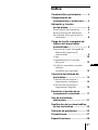
Table Of Contents
Main Features .............................. 4
Checking the Components and
Accessories ................................ 5
Location and Function of Parts ... 6
Front Panel of the Transmitter .......... 6
Rear Panel of the Transmitter ............ 7
Headphone Part Descriptions ........... 8
Charging the Supplied
Rechargeable Nickel-metal
Hydride battery ........................ 9
Inserting the supplied rechargeable
nickel-metal hydride battery .........
9
Charging............................................. 10
Checking the battery power ............ 12
Using the headphones with alkaline
batteries (sold separately) ............
13
Connecting the Headphone
System ..................................... 14
Connecting the transmitter to
analog components .......................
14
Connecting the transmitter to
digital components .......................
15
Listening to a Connected
Component ............................. 17
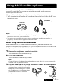
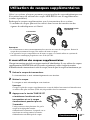
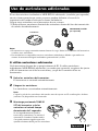
Using Additional Headphones.. 21
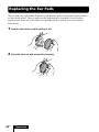
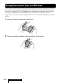
Replacing the Ear Pads .............. 22
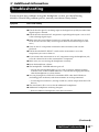
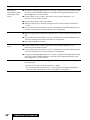
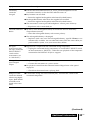
Troubleshooting......................... 23
Precautions................................. 27
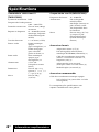
Specifications ............................. 28

4
US
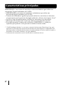
Main Features
The MDR-RF5000K is a wireless stereo headphone system using 2.4 GHz wireless
digital transmission*
1
.
• The MDR-RF5000K is a wireless headphone system using 2.4 GHz wireless digital
transmission.
• Wireless transmission means you can use these headphones anywhere indoors
without worrying about things getting in the way. (Range: Up to approx. 30m)*
2
• Battery is automatically charged by placing the headphones on the transmitter.
• Self-adjusting mechanism headband eliminating the need for adjustment.
• The number of dedicated headphones (MDR-RF5000, sold separately) can be
increased to let more people listen in to the same sound.
*
1
“SYNIC Intelligent Wireless” is a trademark of Syncomm Technology Corp. to represent
uncompressed digital radio frequency transmission technology. This technology employs a
radio frequency carrier, by which audio signals are transmitted with minimum delay and high
fidelity.
*
2
Transmission distance varies depending on conditions of use.

Preparation
5
US
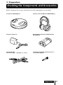
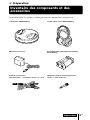
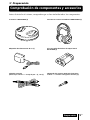
Checking the Components and Accessories
Before setting up the system, check that all of the components are included.
Wireless stereo headphones MDR-RF5000 (1)Transmitter TMR-RF5000 (1)
1 Preparation
AC power adaptor (1) Rechargeable nickel-metal hydride battery
BP-HP2000 (1)
Connecting cable
(stereo mini plug y pin plug × 2), 1 m (1)
Unimatch plug adaptor (stereo mini jack y
stereo phone plug) (1)

Preparation
6
US
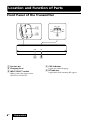
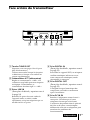
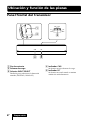
Front Panel of the Transmitter
CHG RF
4
1
2
3
L
A
T
I
G
I
D
G
O
L
A
N
A
T
C
E
L
E
S
T
U
P
N
I
5
Location and Function of Parts
1 Contact pin
2 Charging lever
3 INPUT SELECT switch
Slide to select the input source
(DIGITAL/ANALOG).
4 CHG indicator
Lights red while charging.
5 RF indicator
Lights blue while emitting RF signals.

Preparation
7
US
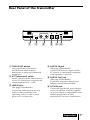
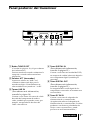
Rear Panel of the Transmitter
AT T
TUNE/ID SET
LLINE IN
DIGITAL IN DIGITAL OUT
(THROUGH)
R
0dB -8dB
DC IN 9V
12 3 456
1 TUNE/ID SET button
(See pages 19 and 21 for details.)
Use this button when reception
deteriorates, or when using additional
headphones.
2 ATT (attenuator) switch
Set this switch to “0 dB” if the volume is
too low for analog input. Normally, this
switch should be set to “–8 dB.”
3 LINE IN jacks
(See page 14 for details.)
Connect the audio output jacks on an
audio or video component (sold
separately), such as a video cassette
player or TV, to these jacks.
4 DIGITAL IN jack
(See page 15 for details.)
Connect a DVD device, digital satellite/
TV receiver, or other digital component
(sold separately) to this jack.
5 DIGITAL OUT jack
(See page 15 for details.)
Connected components' digital signal
integrity retained when installed.
6 DC IN 9V jack
Connect the supplied AC power adaptor
to this jack. (Be sure to use the supplied
AC power adaptor. Using products with a
different plug polarity or other
characteristics can cause a malfunction.)

Preparation
8
US
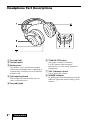
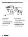
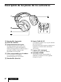
1 Ear pad (left)
2 Contact point
3 Battery case
This battery case is for the rechargeable
nickel-metal hydride battery (supplied) or
commercially available (size AA) alkaline
batteries only.
4 Self-adjusting band
The headphones automatically turn on
when you put them on.
5 Ear pad (right)
V
O
L
T
U
N
E
/ I
D
S
E
T
T
U
N
E
/ I
D
S
E
T
6 TUNE/ID SET button
(See pages 19 and 21 for details.)
Use this button when reception
deteriorates, or when using additional
headphones.
7 VOL (Volume) control
Use to adjust the volume.
8 POWER indicator
By pulling up the self-adjusting band, the
indicator lights blue when battery power
remains.
Headphone Part Descriptions

Preparation
9
US
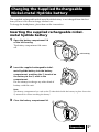
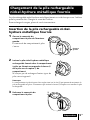
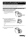
Charging the Supplied Rechargeable
Nickel-metal Hydride battery
The supplied rechargeable nickel-metal hydride battery is not charged from the first
time you use it. Be sure to charge it before use.
To charge the headphones, place them on the transmitter.
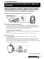
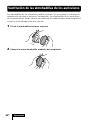
Inserting the supplied rechargeable nickel-
metal hydride battery
1 Open the battery compartment lid
of the left housing.
The battery compartment lid comes
off.
2 Insert the supplied rechargeable nickel-
metal hydride battery into the battery
compartment, matching the 3 terminal on
the battery to the 3 mark in the
compartment.
Do not attempt to charge any other kind of
battery with this unit.
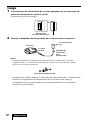
Note
The battery compartment has a tab on the # side which holds the battery in place. Insert the
# terminal first when installing the battery.
3 Close the battery compartment lid.
1
2
Left housing

Preparation
10
US
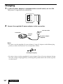
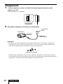
Charging
1 If your AC power adaptor is equipped with an on/off switch, set it to ON.
The power is supplied to the transmitter.
2 Connect the supplied AC power adaptor to the transmitter.
Notes
• Be sure to use the supplied AC power adaptor. Using AC adaptors with different plug
polarity or other characteristics can cause product failure.
• Be sure to always use the supplied AC power adaptor. Even AC power adaptors having
the same voltage and plug polarity can damage this product due to the current capacity
or other factors.
Unified polarity plug
On/off switch
To an AC outlet
AC power adaptor
(supplied)
To DC IN
9V jack
Transmitter

Preparation
11
US
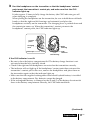
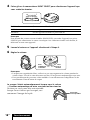
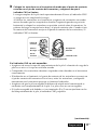
3 Rest the headphones on the transmitter so that the headphones’ contact
point meets the transmitter’s contact pin, and make sure that the CHG
indicator lights up.
It takes approx. 3 hours to fully charge the battery (the CHG indicator goes off
when charging is complete).
When placing the headphones on the transmitter, be sure to hold them with both
hands so that the right and left housings are horizontal, and place the
headphones vertically on the transmitter. The charging lever is pushed down and
the contact pin comes up. When the transmitter’s contact pin meets the
headphones’ contact point, the CHG indicator lights up.
If the CHG indicator is not lit
• Be sure to close the battery compartment lid. The battery charge function is not
activated when the lid is not fully closed.
• Check if the right and left headphones are rested on the transmitter correctly.
• The indicator will not light up if the headphones’ contact point does not meet the
transmitter’s contact pin. In this case, remove the headphones and place them on
the transmitter again so that the indicator lights up.
• Make sure that the supplied rechargeable nickel-metal hydride battery is installed
in the battery compartment. Dry batteries cannot be charged.
• If the rechargeable battery is damaged or the 3 and # of the battery do not match
those in the battery compartment correctly, the CHG indicator blinks.
(Continued)
Right
housing
Left housing
Contact
point
Contact pin CHG
indicator
Charging
lever

Preparation
12
US
POWER
indicator
To recharge the headphone battery after use
Place the headphones on the transmitter after use. The CHG indicator lights up, and
the RF indicator goes off, and then charging starts.
Since the built-in timer recognizes when charging is complete (approx. 3 hours), there
is no need to remove the headphones from the transmitter after charging has
completed.
Notes
• The transmitter automatically turns off while charging the battery.
• This system is designed to charge only the supplied rechargeable battery, type BP-HP2000, for
safety. Note that other types of rechargeable batteries cannot be charged with this system.
• If dry batteries are installed, they cannot be charged.
• Do not attempt to use the supplied BP-HP2000 rechargeable battery with other components. It
is for use with this system only.
• Charge in an environmental temperature of between 0˚C and 40˚C (between 32˚F and 104˚F).
Otherwise, the battery may not be fully charged.
• Do not touch the contact pin of the transmitter. If a contact pin becomes dirty, charging may
not be possible.
• Charging may not be completed if the transmitter’s contact pin and headphones’ contact point
are dusty. Wipe them with a cotton bud, etc.
Charging and usage time
Approx. charging time Approx. usage time*
1
3 hours*
2
7 hours*
3
*
1
at 1 kHz, 1 mW + 1 mW output
*
2
hours required to fully charge an empty battery
*
3
Time may vary, depending on the temperature or conditions of use.
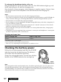
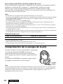
Checking the battery power
Pull up the self-adjusting band and check the POWER
indicator located on the right housing. The battery is
still usable when the indicator lights blue.
Charge the rechargeable battery or install new alkaline
batteries if the POWER indicator does not light up.
Note
The rechargeable nickel-metal hydride battery should be replaced with a new one when it lasts
only half the expected time, after a full charge has been performed. The rechargeable battery,
type BP-HP2000, is not commercially available. You can order the battery from the store where
you purchased this system, or at your nearest Sony dealer.

Preparation
13
US
Using the headphones with alkaline batteries
(sold separately)
Commercially available (size AA) alkaline batteries can also be used to power the
headphones. Install the batteries in the same manner as described in “Inserting the
supplied rechargeable nickel-metal hydride battery” (page 9).
When dry batteries are installed, the battery charge function is not activated.
Battery life
Battery Approx. hours*
1
Sony alkaline batteries 5 hours*
2
LR6(SG)
*
1
at 1 kHz, 1 mW + 1 mW output
*
2
Time may vary, depending on the temperature or conditions of use.
Notes on batteries
• Do not charge a dry battery.
• Do not carry a battery together with coins or metallic objects. Heat can be generated by the
battery if its positive and negative terminals are accidentally shorted.
• When you are not going to use the unit for a long time, remove the batteries to avoid damage
from battery leakage or corrosion.

Connection
14
US
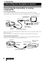
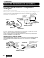
Connecting the Headphone System
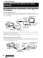
Connecting the transmitter to analog
components
Connecting cable (supplied)
Use the supplied connecting cable (stereo mini-plug y pin plug × 2) when
connecting a stereo mini-jack (line out jack or headphone jack) to the LINE IN jacks.
In this case, set the volume on the player at a medium level. Noise can occur if the volume on the
player is set too low.
When connecting to a TV headphone jack, sound may not be heard from the TV speaker.
Connecting cables (sold separately)
Use the connecting cable (pin plug × 2 y pin plug × 2) to connect the audio output jacks on a
VCR, TV, etc., to the LINE IN (L/R) jacks on the transmitter.
1 Connection
Connecting cable (supplied)
Audio right
(R, red)
To LINE IN jacks
Audio left
(L, white)
Stereo mini-plug
TV, portable device, etc.
Transmitter
Audio cord (sold separately)
Audio right (R, red)
To LINE IN jacks
Audio left
(L, white)
Transmitter
To audio output jacks
Audio left
(white)
Audio right (red)
VCR, TV, or other
component
Unimatch plug
adaptor (supplied)
to headphones jack
(stereo mini jack)
to headphones
jack (stereo
phone jack)

Connection
15
US
AT T
0dB -8dB
Setting the input level
If the volume is low using the analog input, set the ATT (attenuator) switch to “0 dB.”
Setting Connected components
0 dB TV, portable components, and other components with a low output level
–8 dB Other components (initial settings)
Notes
• Be sure to lower the volume before setting the ATT switch.
• If audio input to the LINE IN jacks is distorted (sometimes, noise can be heard at the same
time), set the ATT switch to “–8 dB.”
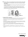
To DIGITAL IN
jack (Black)
Transmitter
DVD device, digital satellite/TV
receiver, or other digital
component having an optical
digital output jack
To optical digital
output jack
Optical digital connecting cable
(sold separately)
Match the orientation of the plug
with the jack, and then insert until
the plug fits into place.
Optical digital connecting
cable (sold separately)
To DIGITAL
OUT jack
(Red)
Equipment with optical
digital input terminal such
as an AV amplifier
To optical digital
input jack
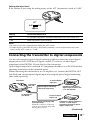
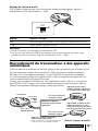
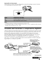
Connecting the transmitter to digital components
Use the sold separately optical digital connecting cable to connect the optical digital
output jack on a CD/DVD device, digital satellite/TV receiver, or other digital
component to the DIGITAL IN jack (black) of the transmitter.
Optical digital output of a connected AV component should be set to PCM. Read their
operating instructions of the connected device.
When connecting the transmitter to an AV amplifier, etc., connect the DIGITAL OUT
jack (Red) and external optical digital input jack using the optical digital connecting
cable (sold separately).
(Continued)

Connection
16
US
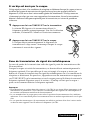
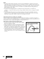
The bend radius of the optical
digital connecting cable should be
no less than 25 mm
(1
inch
)
.
25 mm
(1
inch
)
Notes
• Do not input signals other than PCM to the DIGITAL IN jack. Be sure to set optical digital
output of a connected AV component to PCM. If multi-channel signals are input from a DVD
device, sound may not be transmitted. Note that excessive noise may occur if CD signals
recorded in MPEG-2AAC or DTS format are input to this unit.
• The optical digital connecting cable is an extremely high-precision device and is sensitive to
jolts and external pressure. Therefore, be careful when inserting and removing the cable plug.
• The digital input for the transmitter does not support sampling frequencies of 96 kHz. Set the
digital output setting of the DVD device to 48 kHz when using this system. Noise may be
heard when a 96 kHz digital signal is input.
Connecting cables (sold separately)
Use the optical digital connecting cable POC-15AB (mini-plug y rectangular plug) when
connecting the optical digital output mini-jack on portable DVD players, portable CD players, or
other digital components to the DIGITAL IN jack.
Notes on optical digital connecting cable
• Do not drop objects on the optical digital connecting
cable or expose the cable to shock.
• Grasp the plug to connect or disconnect the cable.
• Be sure that the ends of the optical digital connecting
cable are kept clean. Dust at the ends of the cable can
degrade performance.
•When storing the system, attach the cap to the end of the plug
and be careful not to fold or bend the optical digital
connecting cable with a bend radius less than 25 mm (1 inch).

Operation
17
US
POWER
indicator
(Continued)
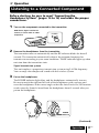
Listening to a Connected Component
Before starting, be sure to read “Connecting the
Headphone System” (pages 14 to 16) and make the proper
connections.
1 Turn on the component connected to the transmitter.
2 Remove the headphones from the transmitter.
The transmitter turns on automatically and the RF indicator blinks for about 5
seconds. The transmitter automatically detects the optimum frequency for
transmission according to your room conditions. The RF indicator lights up when
emission from the transmitter starts.
Signal transmission system
This unit employs a proprietary transmission system using 2.4 GHz frequency.
You can enjoy non-compressed sound with this wireless system.
3 Put on the headphones.
The POWER indicator lights blue, and the headphones automatically turn on.
Be sure to match the right and left side of the headphones with your ears and
wear the headphones at the correct angle so that the Auto Power On/Off function
works correctly. Sound is heard from the headphones about 3 seconds after you
put on the headphones.
1 Operation
POWER
DVD device, digital satellite/TV
receiver, or other audio or video
component

Operation
18
US
L
A
T
I
G
I
D
G
O
L
A
N
A
T
C
E
L
E
S
T
U
P
N
I
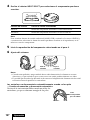
4 Slide the INPUT SELECT switch to select the component you want to listen to.
Position of switch Selected sound source
DIGITAL Sound of the component connected to DIGITAL IN jack.
ANALOG Sound of the component connected to LINE IN jacks.
Note
To listen to dual audio (MAIN/SUB) sound sources, connect to the LINE IN jacks, and then
select the sound source you want to listen to on the player, TV, or other component.
5 Start playback of the component selected in step 4.
6 Adjust the volume.
Notes
• When watching films, be careful not to raise the volume too high in quiet scenes. You
may hurt your ears when a loud scene is played.
• You may hear some noise when you disconnect the AC power adaptor from the
transmitter before removing the headphones.
The headphones automatically turn off when
they are removed
— Auto Power On/Off function
Do not pull up the self-adjusting band when not
in use, as this will consume the battery power.
V
O
L
Raise the
volume
Lower the
volume
Self-adjusting
band

Operation
19
US
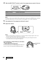
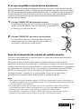
If a beep sound is heard from the headphones
A repeated beep sound is heard if reception conditions deteriorate when the
headphones are outside the signal transmission area, or another wireless apparatus
using 2.4 GHz frequency or microwave oven causes interference. If the beep sound
does not stop after moving closer to the transmitter, let the transmitter detect the
optimum frequency for transmission again following the procedure below.
1 Press TUNE/ID SET on the transmitter once.
The RF indicator blinks and the transmitter detects the
optimum frequency automatically. After detection is
completed, the RF indicator lights up and emission starts.
2 Press TUNE/ID SET on the headphones once.
The headphones detect the frequency of the transmitter
automatically. The beep sound stops when the headphones
start receiving signals.
RF signal transmission area
The approximate RF signal transmission area from the transmitter is up to 30 m.
The transmitter detects the optimum frequency automatically when the headphones
are removed from the transmitter. The sound may be interrupted if the headphones
are out of RF signal transmission area or reception conditions deteriorate. In this case,
move closer to the transmitter or press TUNE/ID SET on the transmitter and
headphones to have them detect the optimum frequency again. See “If a beep sound
is heard from the headphones” on how to detect the optimum frequency.
Notes
• Because this system transmits signals at 2.4 GHz, sound may be interrupted if interference
occurs. This is due to radio frequency characteristics, and is not a malfunction.
• Any noise you hear through the headphones may vary depending on the transmitter position
and room conditions. It is recommended that you place the transmitter in a location that
produces the clearest sound.
• Sound may be interrupted if the transmitter is used with other wireless apparatus using
2.4 GHz frequency, or a microwave oven.
(Continued)

Operation
20
US
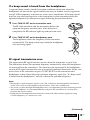
If an audio signal is not input for 5 minutes
RF signal transmission from the transmitter automatically stops when an audio signal
is not input for 5 minutes. The RF signals are automatically transmitted when an
audio signal is input again. RF signal transmission may stop when an extremely low
sound is input for about 5 minutes. If this happens, raise the volume of the connected
audio or video component and lower the volume of the headphones. If signal noise is
output from a component connected to the LINE IN jacks, RF signal transmission may
not stop.
Tip
If RF signal transmission from the transmitter stops when an audio signal is not input for 5
minutes, the RF signals are automatically transmitted when an audio signal is input again.
The RF indicator blinks and the transmitter detects the optimum frequency for transmission. If
the transmission frequency changes after the RF indicator lights up and no sound is heard, press
TUNE/ID SET on the headphones once and tune to the new frequency.
Note
The headphones should be used within the RF signal transmission area (see “RF signal
transmission area” (page 19)).
La page est en cours de chargement...
La page est en cours de chargement...
La page est en cours de chargement...
La page est en cours de chargement...
La page est en cours de chargement...
La page est en cours de chargement...
La page est en cours de chargement...
La page est en cours de chargement...
La page est en cours de chargement...
La page est en cours de chargement...
La page est en cours de chargement...
La page est en cours de chargement...
La page est en cours de chargement...
La page est en cours de chargement...
La page est en cours de chargement...
La page est en cours de chargement...
La page est en cours de chargement...
La page est en cours de chargement...
La page est en cours de chargement...
La page est en cours de chargement...
La page est en cours de chargement...
La page est en cours de chargement...
La page est en cours de chargement...
La page est en cours de chargement...
La page est en cours de chargement...
La page est en cours de chargement...
La page est en cours de chargement...
La page est en cours de chargement...
La page est en cours de chargement...
La page est en cours de chargement...
La page est en cours de chargement...
La page est en cours de chargement...
La page est en cours de chargement...
La page est en cours de chargement...
La page est en cours de chargement...
La page est en cours de chargement...
La page est en cours de chargement...
La page est en cours de chargement...
La page est en cours de chargement...
La page est en cours de chargement...
La page est en cours de chargement...
La page est en cours de chargement...
La page est en cours de chargement...
La page est en cours de chargement...
La page est en cours de chargement...
La page est en cours de chargement...
La page est en cours de chargement...
La page est en cours de chargement...
La page est en cours de chargement...
La page est en cours de chargement...
La page est en cours de chargement...
La page est en cours de chargement...
La page est en cours de chargement...
La page est en cours de chargement...
La page est en cours de chargement...
La page est en cours de chargement...
La page est en cours de chargement...
La page est en cours de chargement...
La page est en cours de chargement...
La page est en cours de chargement...
La page est en cours de chargement...
La page est en cours de chargement...
La page est en cours de chargement...
La page est en cours de chargement...
La page est en cours de chargement...
La page est en cours de chargement...
La page est en cours de chargement...
La page est en cours de chargement...
-
 1
1
-
 2
2
-
 3
3
-
 4
4
-
 5
5
-
 6
6
-
 7
7
-
 8
8
-
 9
9
-
 10
10
-
 11
11
-
 12
12
-
 13
13
-
 14
14
-
 15
15
-
 16
16
-
 17
17
-
 18
18
-
 19
19
-
 20
20
-
 21
21
-
 22
22
-
 23
23
-
 24
24
-
 25
25
-
 26
26
-
 27
27
-
 28
28
-
 29
29
-
 30
30
-
 31
31
-
 32
32
-
 33
33
-
 34
34
-
 35
35
-
 36
36
-
 37
37
-
 38
38
-
 39
39
-
 40
40
-
 41
41
-
 42
42
-
 43
43
-
 44
44
-
 45
45
-
 46
46
-
 47
47
-
 48
48
-
 49
49
-
 50
50
-
 51
51
-
 52
52
-
 53
53
-
 54
54
-
 55
55
-
 56
56
-
 57
57
-
 58
58
-
 59
59
-
 60
60
-
 61
61
-
 62
62
-
 63
63
-
 64
64
-
 65
65
-
 66
66
-
 67
67
-
 68
68
-
 69
69
-
 70
70
-
 71
71
-
 72
72
-
 73
73
-
 74
74
-
 75
75
-
 76
76
-
 77
77
-
 78
78
-
 79
79
-
 80
80
-
 81
81
-
 82
82
-
 83
83
-
 84
84
-
 85
85
-
 86
86
-
 87
87
-
 88
88


Sony MDR-RF5000K Manuel utilisateur
- Taper
- Manuel utilisateur
- Ce manuel convient également à
dans d''autres langues
- English: Sony MDR-RF5000K User manual
- español: Sony MDR-RF5000K Manual de usuario
Documents connexes
-
Sony MDR-RF5000K Mode d'emploi
-
Sony MDR-RF5000 Manuel utilisateur
-
Sony MDR-IF240RK Le manuel du propriétaire
-
Sony MDR-RF4000K Le manuel du propriétaire
-
-
Sony MDR-RF925RK Mode d'emploi
-
-
-
-
Autres documents
-
Philips PET702/75 Manuel utilisateur
-
-
Slick HP921 Manuel utilisateur
-
Acoustic Research AWD205 Manuel utilisateur
-
RCA WHP145 Mode d'emploi
-
Panasonic RPWF6000 Le manuel du propriétaire
-
-
-
Serene TVDirect TV-200 Mode d'emploi