
www.westermo.com
Lynx L210-F2G-EX
Industrial Ethernet 10-port Switch

2
6643-22601

3
6643-22601
General information
Legal information
The contents of this document are provided “as is”. Except as required by applicable law,
no warranties of any kind are made in relation to the accuracy and reliability or contents
of this document, either expressed or implied, including but not limited to the implied
warranties of merchantability and fitness for a particular purpose. Westermo reserves
the right to revise this document or withdraw it at any time without prior notice.
Under no circumstances shall Westermo be responsible for any loss of data or income or
any special, incidental, and consequential or indirect damages howsoever caused.
More information about Westermo can be found at www.westermo.com
Software tools
Related software tools are available at www.westermo.com/support/software-tools.
License and copyright for included Free/Libre Open Source Software
This product includes software developed by third parties, including Free/Libre Open
Source Software (FLOSS). The specific license terms and copyright associated with the
software are included in each software package respectively. Please visit the product web
page for more information.
Upon request, the applicable source code will be provided. A nominal fee may be
charged to cover shipping and media. Please direct any source code request to your nor-
mal sales or support channel.
WeOS Management Guide
This product runs WeOS (Westermo Operation System). Instructions for quick start,
configuration, factory reset and use of USB port are found in the WeOS Management
Guide at www.westermo.com.

4
6643-22601
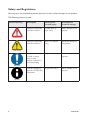
Safety and Regulations
Warning signs are provided to prevent personal injuries and/or damages to the product.
The following levels are used:
Level of warning Description Consequence
personal injury
Consequence
material damage
WARNING
Indicates a potentially
hazardous situation
Possible death or
major injury
Major damage to the
product
CAUTION
Indicates a potentially
hazardous situation
Minor or moderate
injury
Moderate damage to
the product
NOTICE
Provides information
in order to avoid
misuse of the
product, confusion or
misunderstanding
No personal injury Minor damage to the
product
NOTE
Used for highlighting
general, but important
information
No personal injury Minor damage to the
product

5
6643-22601
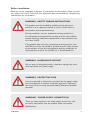
Before installation:
Read this manual completely and gather all information on the product. Make sure that
you understand it fully. Check that your application does not exceed the safe operating
specifications for this product.
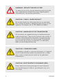
WARNING - SAFETY DURING INSTALLATION
The product must be installed by qualified service personnel
and built in to an apparatus cabinet or similar, where access is
restricted to service personnel only.
During installation, ensure a protective earthing conductor is
first connected to the protective earthing terminal (only valid for
metallic housings). Westermo recommends a cross-sectional area
of at least 4 mm2.
If the product does not have a protective earthing terminal, then
the DINrail must be connected to protective earth. Upon removal
of the product, ensure that the protective earthing conductor, or
the connection to earth via the DIN-rail, is disconnected last.
WARNING - PROTECTIVE FUSE
It must be possible to disconnect manually from the power supply.
Ensure compliance to national installation regulations. Replacing
the internal fuse must only be performed by Westermo qualified
personell.
WARNING - HAZARDOUS VOLTAGE
Do not open an energized product. Hazardous voltage may occur
when connected to a power supply.
WARNING - POWER SUPPLY CONNECTION
There are safety regulations on which power sources that shall
be used in conjunction with the product. Refer to Interface
Specifications.

6
6643-22601
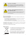
WARNING - REDUCE THE RISK OF FIRE
To reduce the risk of fire, use only telecommunication line cords
with a cable diameter of AWG 26 or larger. Regarding power
cable dimensions, see Interface Specifications.
CAUTION - CORROSIVE GASES
If the product is placed in a corrosive environment, it is important
that all unused connector sockets are protected with a suitable
plug, in order to avoid corrosion attacks on the gold plated
connector pins.
CAUTION - ELECTROSTATIC DISCHARGE (ESD)
Prevent electrostatic discharge damages to internal electronic
parts by discharging your body to a grounding point (e.g. use a
wrist strap).
CAUTION - CLASS 1 LASER PRODUCT
Do not look directly into a fibre optical port or any connected
fibre, although the product is designed to meet the Class 1 Laser
regulations and complies with 21 CFR 1040.10 and 1040.11.
CAUTION - HANDLING OF SFP TRANSCEIVERS
SFP transceivers are supplied with plugs to avoid contamination
inside the optical port. They are very sensitive to dust and dirt. If
the fibre is disconnected from the product, the protective plugs
on the transmitter/receiver must be connected. The protective
plugs must be kept on during transportation. The fibre optics
cables must be handled the same way.

7
6643-22601
Product disposal
CAUTION - HOT SURFACE
Be aware of that the surface of this product may become hot.
When it is operated at high temperatures, the external surface
may exceed Touch Temperature Limit according to the product's
relevant electrical safety standard.
CAUTION - CABLE TEMPERATURE RATING FOR
FIELD TERMINAL WIRES
There may be a requirement on the minimum temperature rating
of the cable to be connected to the field wiring terminals, see
Interface Specifications.
Product disposal
This symbol means that the product shall not be treated
as unsorted municipal waste when disposing of it. It needs
to be handed over to an applicable collection point for
recycling electrical and electronic equipment.
By ensuring this product is disposed of correctly, you will
help to reduce hazardous substances and prevent potential
negative consequences to both environment and human
health, which could be caused by inappropriate disposal.
Care recommendations
Follow the care recommendations below to maintain full operation of product and to
fulfill the warranty obligations:
• Do not drop, knock or shake the product. Rough handling above the specification
may cause damage to internal circuit boards.
• Use a dry or slightly water-damp cloth to clean the product. Do not use harsh
chemicals, cleaning solvents or strong detergents.
• Do not paint the product. Paint can clog the product and prevent proper operation.
If the product is used in a manner not according to specification, the protection provided
by the equipment may be impaired.
If the product is not working properly, contact the place of purchase, nearest Westermo
distributor office or Westermo technical support.

8
6643-22601
ATEX certification
ATEX certification number
Baseefa12ATEX0119X
Standards
EN 60079-0, EN 60079-15
Certification code
Ex nA IIC T3 Gc (-40°C ≤ Ta ≤ +70°C)
ATEX code
II 3G
Specific Conditions of Use
The equipment must be installed in an area of not more than pollution degree 2 in
accordance with IEC/EN 60664-1, and in an enclosure that provides a minimum degree of
protection of at least IP54 and complies with the relevant requirements of EN 60079-0
and EN 60079-15.
All external connections to the equipment and, where applicable, the SFP modules must
not be inserted or removed unless either the area in which the equipment is installed is
known to be non-hazardous, or the circuits connected have been de-energized.
The network cables once installed must be properly fixated by the use of cable ties or
similar to reduce the risk of accidently withdrawing the plugs.
Equipment input parameters
Power Connector: +DC1, +DC2 & -COM
Working Voltage Range = 24 V to 48 VDC.
I/O Connector: ‘Status +’ & ‘Status -’ and ‘Digital in +’ and ‘Digital in -’
Maximum I/P Voltage = 60 VDC.

9
6643-22601
SFP option approved transceivers
SFP Transceivers, 100 Mbit
1100-0131 MLC2, Multimode, LC-Connector, 2 km, 1310 nm
1100-0132 SLC20, Singlemode, LC-Connector, 20 km, 1310 nm
1100-0133 SLC40, Singlemode, LC-Connector, 40 km, 1310 nm
1100-0134 SLC80, Singlemode, LC-Connector, 80 km, 1550 nm
1100-0140 SLC120, Singlemode, LC-Connector, 120 km, 1550 nm
BiDi Transceivers, 100 Mbit
1100-0145 SLC15-BiDi-A, Singlemode, BiDi, 20 km, 1310 nm TX, 1550 nm RX
1100-0146 SLC15-BiDi-B, Singlemode, BiDi, 20 km, 1550 nm TX, 1310 nm RX
1100-0152 MLC2-BiDi-A, Multimode, BiDi, 2 km, 1310 nm TX, 1550 nm RX
1100-0153 MLC2-BiDi-B, Multimode, BiDi, 2 km, 1550 nm TX, 1310 nm RX
SFP Transceivers, 1 Gbit
1100-0144 GMLC550-SX, Multimode, LC-Connector, 550 m, 850 nm, SX
1100-0147 GMLC2-SX+, Multimode, LC-Connector, 2 km, 1310 nm, SX+
1100-0141 GSLC10-LX, Singlemode, LC-Connector, 10 km, 1310 nm, LX
1100-0142 GSLC50-XD, Singlemode, LC-Connector, 50 km, 1550 nm, XD
1100-0143 GSLC80-ZX, Singlemode, LC-Connector, 80 km, 1550 nm, ZX
1100-0171 GSLC110-EZX, Singlemode, LC-Connector, 110 km, 1550 nm, EZX
BiDi Transceiver, 1 Gbit
1100-0156 GSLC20-BiDi-A, Singlemode, BiDi, 20 km, 1310 nm TX, 1490 nm RX
1100-0157 GSLC20-BiDi-B, Singlemode, BiDi, 20 km, 1490 nm TX, 1310 nm RX
Copper Transceiver, 1 Gbit
1100-0148 GC100, Copper, RJ45, 100 m, 1000BaseT

10
6643-22601
ATEX-Zertifizierung
ATEX-Zulassungsnummer
Baseefa12ATEX0119X
Standards
EN 60079-0, EN 60079-15
Zertifizierungscode
Ex nA IIC T3 Gc (-40°C ≤ Ta ≤ +70°C)
ATEX-Code
II 3G
Spezifische Einsatzbedingungen
Die Geräte müssen in einem Bereich welcher einem maximalen Verschmutzungsgrad der
Stufe 2 gemäß IEC/EN 60664-1 entspricht und in einem Gehäuse, das einen Schutzgrad
von mindestens IP54 bietet und die relevanten Anforderungen von N 60079-0 und EN
60079-15 erfüllt, installiert werden.
Alle äußeren Anschlüsse des Gerätes und auch die SFP-Module dürfen nur dann
verbunden oder getrennt werden, wenn entweder der Bereich, in dem das Gerät
installiert ist, nachweislich ungefährlich ist, oder die verbundenen Stromkreise
spannungsfrei sind.
Die Netzwerkkabel müssen nach der Installation mithilfe von Kabelbindern oder
ähnlichem Material ordnungsgemäß befestigt werden, um ein versehentliches Abziehen
der Stecker zu verhindern.
Eingangsparameter der Geräte
Stromversorgung: +DC1, +DC2 & -COM
Betriebsspannungsbereich = 24 V to 48 VDC.
I/O-Anschluss: ‘Status +’ & ‘Status -’ und ‘Digital in +’ und ‘Digital in -’
Maximale I/P-Spannung = 60 VDC.

11
6643-22601
Für SFP-Option zugelassene Transceiver
SFP-Transceiver, 100 Mbit
1100-0131 MLC2, Multimode, LC-Anschluss, 2 km, 1310 nm
1100-0132 SLC20, Singlemode, LC-Anschluss, 20 km, 1310 nm
1100-0133 SLC40, Singlemode, LC-Anschluss, 40 km, 1310 nm
1100-0134 SLC80, Singlemode, LC-Anschluss, 80 km, 1550 nm
1100-0140 SLC120, Singlemode, LC-Anschluss, 120 km, 1550 nm
BiDi-Transceiver, 100 Mbit
1100-0145 SLC15-BiDi-A, Singlemode, BiDi, 20 km, 1310 nm TX, 1550 nm RX
1100-0146 SLC15-BiDi-B, Singlemode, BiDi, 20 km, 1550 nm TX, 1310 nm RX
1100-0152 MLC2-BiDi-A, Multimode, BiDi, 2 km, 1310 nm TX, 1550 nm RX
1100-0153 MLC2-BiDi-B, Multimode, BiDi, 2 km, 1550 nm TX, 1310 nm RX
SFP-Transceiver, 1 Gbit
1100-0144 GMLC550-SX, Multimode, LC-Anschluss, 550 m, 850 nm, SX
1100-0147 GMLC2-SX+, Multimode, LC-Anschluss, 2 km, 1310 nm, SX+
1100-0141 GSLC10-LX, Singlemode, LC-Anschluss, 10 km, 1310 nm, LX
1100-0142 GSLC50-XD, Singlemode, LC-Anschluss, 50 km, 1550 nm, XD
1100-0143 GSLC80-ZX, Singlemode, LC-Anschluss, 80 km, 1550 nm, ZX
1100-0171 GSLC110-EZX, Singlemode, LC-Anschluss, 110 km, 1550 nm, EZX
BiDi-Transceiver, 1 Gbit
1100-0156 GSLC20-BiDi-A, Singlemode, BiDi, 20 km, 1310 nm TX, 1490 nm RX
1100-0157 GSLC20-BiDi-B, Singlemode, BiDi, 20 km, 1490 nm TX, 1310 nm RX
Kupfer-Transceiver, 1 Gbit
1100-0148 GC100, Kupfer, RJ45, 100 m, 1000BaseT

12
6643-22601
Certification ATEX
Numéro de certification ATEX
Baseefa12ATEX0119X
Normes
EN 60079-0, EN 60079-15
Code de certification
Ex nA IIC T3 Gc (-40°C ≤ Ta ≤ +70°C)
Code ATEX
II 3G
Conditions spéciales d'utilisation
L'équipement doit être installé dans une zone où le degré de pollution ne dépasse pas le
degré 2 conformément à l'IEC/EN 60664-1, et dans un boîtier qui fournit un niveau de
protection au moins égal à IP54 et conforme aux exigences applicables à EN 60079-0 et
EN 60079-15
Toutes les connexions externes à l'équipement et, le cas échéant, les modules SFP ne
doivent pas être insérés ou retirés sauf si la zone dans laquelle l'équipement est installé
est reconnue comme non dangereuse, ou si les circuits raccordés sont hors-tension.
Une fois les câbles réseau installés, ils doivent être correctement fixé grâce à des attaches
de câbles ou autre élément semblable afin de réduire le risque de débranchement
accidentel.
Paramètres d'entrée des équipements
Connecteur d'alimentation: +DC1, +DC2 & -COM
Double entrée d'alimentation 24V à 48VCC
ConnecteurE/S: «Statut +» et «Statut -» et «Entrée digitale +» et «Entrée digitale -»
Tension maximale I/P = 60 VCC.

13
6643-22601
Transmetteurs optionnels SFP certifiés
Transmetteurs SFP, 100 Mbit
1100-0131 MLC2, multimode, connecteur LC, 2 km, 1310 nm
1100-0132 SLC20, monomode, connecteur LC, 20 km, 1310 nm
1100-0133 SLC40, monomode, connecteur LC, 40 km, 1310 nm
1100-0134 SLC80, monomode, connecteur LC, 80 km, 1550 nm
1100-0140 SLC120, monomode, connecteur LC, 120 km, 1550 nm
Transmetteurs Bi-Di, 100 Mbit
1100-0145 SLC15 Bi-Di A, monomode, Bi-Di, 20 km, 1310 nm TX, 1550 nm, RX
1100-0146 SLC15-Bi-Di-B, monomode, Bi-Di, 20 km, 1550 nm TX, 1310 nm RX
1100-0152 MLC2-BiDi-A, multimode, Bi-Di, 2 km, 1310 nm TX, 1550 nm RX
1100-0153 MLC2-BiDi-B, multimode, Bi-Di, 2 km, 1550 nm TX, 1310 nm RX
Transmetteurs SFP, 1 Gbit
1100-0144 GMLC550-SX, multimode, connecteur LC, 550 m, 850 nm, SX
1100-0147 GMLC2-SX+, multimode, connecteur LC, 2 km, 1310 nm, SX+
1100-0141 GSLC10-LX, monomode, connecteur LC, 10 km, 1310 nm, LX
1100-0142 GSLC50-XD, monomode, connecteur LC, 50 km, 1550 nm, XD
1100-0143 SLC80, monomode, connecteur LC, 80 km, 1550 nm, ZX
1100-0171 GSLC110, monomode, connecteur LC, 110 km, 1550 nm, EZX
Transmetteurs Bi-Di, 1 Gbit
1100-0156 GSLC20-BiDi-A, monomode, Bi-Di, 20 km, 1310 nm TX, 1490 nm RX
1100-0157 GSLC20-BiDi-B, monomode, Bi-Di, 20 km, 1490 nm TX, 1310 nm RX
Transmetteurs cuivre, 1 Gbit
1100-0148 GC100, cuivre, RJ45, 100m, 1000BaseT

14
6643-22601
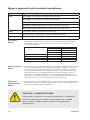
Agency approvals and standards compliance
Type Approval / Compliance
EMC
EN 61000-6-1, Immproducty residential environments
EN 61000-6-2, Immproducty industrial environments
EN 61000-6-4, Emission industrial environments
EN 50121-4, Railway signalling and telecommunications apparatus
IEC 62236-4, Railway signalling and telecommunications apparatus
Safety
UL 62368-1, Safety Communication Technology
Marine
DNV GL rules for classification - Ships and offshore products
Ex
EN 60079-0, EN 60079-15
FCC Part 15.105
Notice:
This equipment has been tested and found to comply with the limits for a Class A digital
device, pursuant to Part 15 of the FCC Rules. These limits are designed to provide
reasonable protection against harmful interference when the equipment is operated
in a commercial environment. This equipment generates, uses, and can radiate radio
frequency energy and, if not installed and used in accordance with the instruction
manual, may cause harmful interference to radio communications. Operation of this
equipment in a residential area is likely to cause harmful interference in which case the
user will be required to correct the interference at his own expense.
Corrosive
environment
Notice:
This product has been successfully tested in a corrosion test according to IEC 60068-2-
60, method 3. This means that the product meets the requirements to be placed in an
environment classified as ISA-S71.04 class G3.
CAUTION - CORROSIVE GASES
If the product is placed in a corrosive environment, it is important
that all unused connector sockets are protected with a suitable
plug, in order to avoid corrosion attacks on the gold plated
connector pins.
UL 62368-1
Notice:
This product has been tested and found compliant to UL 62368-1, Safety for
Communication Technology. In accordance with the definitions of the standard, this
product shall be handled by instructed personell. Energy source classifications are
according to following:
Electrical energy source Power port ES1
Serial port ES1
Ethernet port ES1, TNV-1
I/O port ES1
Power source Power port PS3
Thermal energy source Enclosure TS1
Mechanical energy source Enclosure MS1
Radiation energy source SFP RS1

15
6643-22601
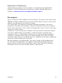
Declaration of Conformity
Hereby, Westermo declares that this product is in compliance with applicable EU
directives. The full EU declaration of conformity and other detailed information is
available at www.westermo.com/support/product-support.
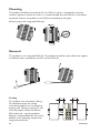
Description
Lynx is an industrial switch made for harsh enviroments. The switch can be used in ether
100 Mbit or Gigabit networks due to our multi-rate SFP solution. Lynx can also be used
together with our previous Lynx-series of switches.
Our unique FRNT (Fast Recovery of Network Topology) technology is the fastest
protocol on the market to re-configure a network in the event of any link or hardware
failure. That is why Lynx is used in safety critical applications such as tunnels, traffic signal
control and railway systems.
Installations in harsh environments and places with heavy electrical interference require
the use of a reliable media. Lynx provides a number of solutions using fibre optic
transceivers. Multi- or singlemode transceivers can be used to build point-to-point or
redundant ring networks with ranges up to 120 km between each switch. Our BIDI
transceiver, which transmits and receives data on a single fibre can be used in applications
where the number of fibre cores are limited.
Real-time properties are implemented in the switch in order to achieve determinism
for real time critical applications. Lynx supports QoS (Quality of Service) with four
priority queues and strict priority scheduling as well as HoL (Head of Line Blocking
Prevention). All to assure that the data network is deterministic.

16
6643-22601
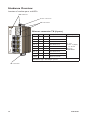
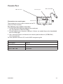
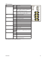
Hardware Overview
Location of interface ports and LEDs
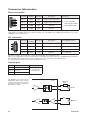
Ethernet connection TX (8 ports)
Position Signale Direction Description Input/output values
No.1 TD+ In/Out Transmitted/Received data
Per port:
U = ± 1 V (4V/μs)
I = ± 20 mA
Data rate:
10/100 Mbit/s
No. 2 TD- In/Out Transmitted/Received data
No. 3 RD+ In/Out Transmitted/Received data
No. 4 - Not Connected
No. 5 - Not Connected
No. 6 RD- In/Out Transmitted/Received data
No. 7 - Not Connected
No. 8 - Not Connected
Shield Connected to PE
Galvanically isolated via signal transformers and capacitively isolated to
GND/PE through a 2kV 1000pF capacitor.
LED Indicators
Power connection
SFP transceivers
I/O connection

17
6643-22601
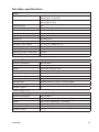
Interface specifications
Power
Operating voltage Rated: 24 to 48 VDC
Operating: 19 to 60 VDC
Rated current 240 mA @ 24 VDC
120 mA @ 48 VDC
Rated frequency DC
Inrush current, I
2
t 22.7·10
-3
A
2
s @ 48 VDC
Startup current* 2 x Rated current
Polarity Reverse polarity protected
Redundant power input Ye s
Isolation to
All other ports
Connection Detachable screw terminal
Conductor cross section
0.2 - 2.5 mm
2
(AWG 24 - 12)
Stripping length cable 7 mm
Tightening torque, terminal screw 0.5 -0.6 Nm
Tightening torque, screw flange 0.3 Nm
Shielded cable Not required
* Recommended external supply current capability for proper startup
Ethernet TX
Electrical specification
IEEE std 802.3
Data rate 10 Mbit/s, 100 Mbit/s, manual or auto
Duplex Full or half, manual or auto
Circuit type TNV-1
Transmission range Up to 150 m with CAT5e cable or better*
Isolation to
All other ports
Connection RJ-45, auto MDI/MDI-X
Shielded cable
Shielded CAT5e or better is recommended
Conductive housing Ye s
Number of ports 8
* Refer to Safety section.
Ethernet SFP pluggable connections (FX or TX)
Electrical specification
IEEE std 802.3
Data rate 100 Mbit/s or 1000 Mbit/s transceivers supported
Duplex Full or Auto, depending on transceiver
Transmission range Depending on tranceiver
Connection SFP slot holding fibre transceiver or copper transceiver
Number of ports 1 or 2

18
6643-22601
I/O / Relay output
Maximum voltage/current 60 VDC / 80 mA
Contact resistance Max 30 Ω
Isolation to
All other ports
Connection Detachable screw terminal
Conductor cross section
0.14 - 1.5 mm
2
(AWG 28 - 16)
Stripping length cable 7 mm
Tightening torque, terminal screw 0.22 -0.25 Nm
Tightening torque, screw flange 0.3 Nm
I/O / Digital input
Maximum voltage/load current 60 VDC / 2 mA
Voltage levels Logic one: >12V
Logic zero: <1V
Isolation to
All other ports
Connection Detachable screw terminal
Conductor cross section
0.14 - 1.5 mm
2
(AWG 28- 16)
Stripping length cable 7 mm
Tightening torque, terminal screw 0.22 -0.25 Nm
Tightening torque, screw flange 0.3 Nm
Console
Electrical specification TTL-level
Data rate 115.2 kbit/s
Data format 8 data bits, no parity, 1 stop bit, no flow control
Circuit type SELV
Connection 2.5 mm jack, use only Westermo cable 1211-2027

19
6643-22601
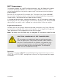
SFP Transceivers
The product supports UL and IEC certified transceivers only. See Westermo's modular
transceivers datasheets 100 Mbit and 1 Gbit for supported SFP transceivers, which
can be downloaded from the product support pages at www.westermo.com/support/
productsupport.
Each SFP slot can hold one SFP transceiver. See "Transceiver User Guide 6100-0000"
for transceiver handling instructions, which also can be downloaded from the product
support pages at www.westermo.com/support/product-support.
In the event of contamination, the optical connectors in the SFP transceivers should only
be cleaned by the use of forced nitrogen and some kind of cleaning stick. Recommended
cleaning fluids are methyl-, ethyl-, isopropyl- or isobutyl alcohol, hexane or naphtha
Supported transceivers
Firmware prior to 4.4.0 accepts Westermo branded transceivers only. From 4.5.0 other
transceivers are accepted with a notice and the product will no longer be UL approved.
Temp.specifications are also depending on the used transeivers.
Note: To comply with UL 62368-1 only UL recognized SFP transceivers should be used.
CAUTION - HANDLING OF SFP TRANSCEIVERS
SFP transceivers are supplied with plugs to avoid contamination
inside the optical port. They are very sensitive to dust and dirt. If
the fibre is disconnected from the product, the protective plugs
on the transmitter/receiver must be connected. The protective
plugs must be kept on during transportation. The fibre optics
cables must be handled the same way.
Deviations
With copper transceiver 1100-0148 the specified operating temperature on Lynx is 0 to
+50ºC (32 to +122°F). FRNT reconfiguration times can not be guaranteed with copper
transceivers.

20
6643-22601
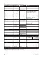
Type tests and environmental conditions
Environmental phenomena Basic standard Description Test levels
ESD EN 61000-4-2 Enclosure Contact: ±6 kV
Air: ±8 kV
Fast transients EN 61000-4-4 Power port
±2 kV
Signal ports
Earth port ±1 kV
Surge EN 61000-4-5 Power port
L-E: ±2 kV, 42 Ω, 0.5 μF, 1.2/50 μs
L-L: ±2 kV, 42 Ω, 0.5 μF, 1.2/50 μs
L-E: ±2 kV, 12 Ω, 9 μF, 1.2/50 μs
L-L: ±1 kV, 2 Ω, 18 μF, 1.2/50 μs
Ethernet ports L-E: ±2 kV, 12 Ω, 1.2/50 μs
Power frequency magnetic field EN 61000-4-8 Enclosure 300 A/m; 0, 16.7, 50 Hz
Pulsed magnetic field EN 61000-4-9 Enclosure 300 A/m
Radiated RF immunity
EN 61000-4-3 Enclosure
20 V/m @ (80 - 2700) MHz
10 V/m @ (2700 - 6000) MHz
1 kHz sine, 80% AM
Conducted RF immunity
EN 61000-4-6 Power port
10 V, 80% AM, 1 kHz; (0.15 - 80) MHz
Signal ports
Earth port
Radiated RF emission CISPR 16-2-3
ANSI C63.4
Enclosure
Class A (Industrial), 30 MHz to 6 GHz
FCC Part 15 B, Class A,
30 MHz to 6.5 GHz
Conducted RF emission CISPR 16-2-1
ANSI C63.4
Power port
Class B
Signal ports
Dielectric strength
UL 62368-1
Power port to all
other ports
1.5 kVrms, 50 Hz, 1 min
Signal ports to all
other ports
Environmental
Temperatures EN 60068-2-1
EN 60068-2-2
Operating
-40 to +70°C (-40 to +158°F)*
Storage and transport
-50 to +85°C (-58 to +185°F)
Humidity EN 60068-2-30 Operating
5 to 95 % relative humidity
Storage and transport
Altitude Operating
2000 m / 70 kPa
Service life Operating
10 years
Reliability prediction (MTBF) MIL-HDBK- 217F Operating
630,000 hours
Vibration IEC 60068-2-6
(sine)
Operating
3 - 13.2 Hz: 1mm
13.2 - 100 Hz: 0.7 g
5.5 - 30 Hz: 1.5 g
30 - 50 Hz: 0.42 mm
50 - 500 Hz: 4.2 g**
Shock IEC 60068-2-27 Operating 30 g, 11 ms
100 g, 6 ms**
Bump IEC 60068-2-27 Operating
10 g, 11 ms, x1000
Packaging
Enclosure
UL 62368-1
Zinc Fire enclosure
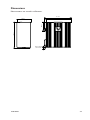
Dimension W x H x D
With connectors
52.5 x 100 x 101 mm
52.5 x 119 x 101 mm
Weight 0.7 kg
Degree of protection EN 60529 Enclosure IP 40
Cooling Convection
** Refer to “Safety” section.
** Might require Ethernet cables to be fastened close to the product.
La page est en cours de chargement...
La page est en cours de chargement...
La page est en cours de chargement...
La page est en cours de chargement...
La page est en cours de chargement...
La page est en cours de chargement...
La page est en cours de chargement...
La page est en cours de chargement...
-
 1
1
-
 2
2
-
 3
3
-
 4
4
-
 5
5
-
 6
6
-
 7
7
-
 8
8
-
 9
9
-
 10
10
-
 11
11
-
 12
12
-
 13
13
-
 14
14
-
 15
15
-
 16
16
-
 17
17
-
 18
18
-
 19
19
-
 20
20
-
 21
21
-
 22
22
-
 23
23
-
 24
24
-
 25
25
-
 26
26
-
 27
27
-
 28
28


dans d''autres langues
- English: Westermo L210-F2G-EX User guide
Documents connexes
-
Westermo L110-F2G-EX Mode d'emploi
-
-
Westermo L206-F2G-EX Mode d'emploi
-
Westermo L106-F2G EX Mode d'emploi
-
-
-
-
-
Westermo L110-F2G Mode d'emploi
-
Westermo L210-F2G Fiche technique
Autres documents
-
Comnet SFP Modules Fiche technique
-
Hirschmann SPIDER&bnsp;II&bnsp;16TX&bnsp;EEC, SPIDER&bnsp;II&bnsp;16TX/2DS-S&bnsp;EEC Manuel utilisateur
-
-
Technicolor XB7 Mode d'emploi
-
ADTRAN 1442442F1 Guide de démarrage rapide
-
IKUSI FSP-305 Manuel utilisateur
-
Asco Series 881 Cylinder Sensor Le manuel du propriétaire
-
-
-