
USER INSTRUCTION MANUAL
TALON™ SELF RETRACTING LIFELINES
This manual is intended to meet the Manufacturer’s Instructions as
required by ANSI Z359.14 and should be used as part of an employee
training program as required by OSHA.
© Copyright 2007, DB Industries, Inc.
Talon SRLs
Instruction Manual 5911858 Rev. J
(See back page for model numbers)

2
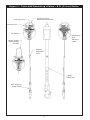
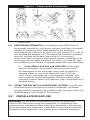
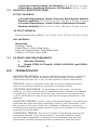
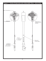
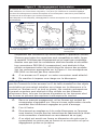
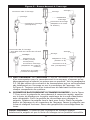
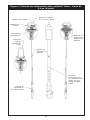
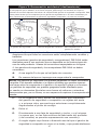
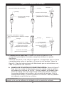
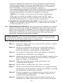
Figure 1 - Talon Self Retracting Lifeline - 8 ft. (2.4 m) Series
Locking Pin
ID Label
Order Picker
Attachment
Handle
Quick Connect
Attachment Handle
Impact
Indicator
Fold
Inspection
and
Warning
Label
i-Safe
RFID Tag
Self Locking
Snap Hook
Locking Lever

3
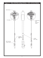
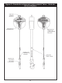
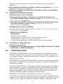
Figure 2 - Talon Self Retracting Lifeline - 16 ft. (4.9 m) Series
Swivel Eye
ID Label
i-Safe
RFID Tag
Self Locking
Snap Hook
Impact
Indicator
Fold
Inspection
and
Warning
Label

4
SAFETY INFORMATION
Please read, understand, and follow all safety information contained in these
instructions prior to the use of this Self-Retracting Device (SRD). FAILURE TO DO
SO COULD RESULT IN SERIOUS INJURY OR DEATH.
These instructions must be provided to the user of this equipment. Retain these
instructions for future reference.
INTENDED USE:
This Self-Retracting Device is intended for use as part of a complete personal fall protection
system.
Use in any other application including, but not limited to, material handling, recreational
or sports related activities, or other activities not described in the User Instructions, is not
approved by 3M and could result in serious injury or death.
This device is only to be used by trained users in workplace applications.
! WARNING
This Self-Retracting Device is part of a personal fall protection system. It is expected that all
users be fully trained in the safe installation and operation of their personal fall protection
system. Misuse of this device could result in serious injury or death. For proper
selection, operation, installation, maintenance, and service, refer to these User Instructions
including all manufacturer recommendations, see your supervisor, or contact 3M Technical
Services.
• To reduce the risks associated with working with an SRD which, if not avoided,
could result in serious injury or death:
- Before each use, inspect the SRD and check for proper locking and retraction.
- If inspection reveals an unsafe or defective condition, remove the device from
service and repair or replace according to the User Instructions.
- If the SRD has been subjected to fall arrest or impact force, immediately remove the
SRD from service and label the device ‘UNUSABLE’.
- Ensure the lifeline is kept free from any and all obstructions including, but not limited
to; entanglement with moving machinery or equipment (e.g., the top drive of oil
rigs), other workers, yourself, surrounding objects, or impact from overhead objects
that could fall onto the lifeline or the worker.
- Never allow slack in the lifeline. Do not tie or knot the lifeline.
- Attach the unused leg(s) of the Harness Mounted SRD to the parking attachment(s)
of the harness if equipped.
- Do not use in applications that have an obstructed fall path. Working on slowly
shifting material, such as sand or grain, or within conned or cramped spaces, may
not allow the worker to reach sufcient speed to cause the SRD to lock. A clear path
is required to assure positive locking of the SRD.
- Avoid sudden or quick movements during normal work operation. This may cause
the device to lock up.
- Ensure that fall protection systems/subsystems assembled from components made
by different manufacturers are compatible and meet the requirements of applicable
standards, including the ANSI Z359 or other applicable fall protection codes,
standards, or requirements. Always consult a Competent and/or Qualied Person
before using these systems.
• To reduce the risks associated with working at height which, if not avoided,
could result in serious injury or death:
- Ensure your health and physical condition allow you to safely withstand all of the
forces associated with working at height. Consult with your doctor if you have any
questions regarding your ability to use this equipment.
- Never exceed allowable capacity of your fall protection equipment.
- Never exceed maximum free fall distance of your fall protection equipment.
- Do not use any fall protection equipment that fails pre-use or other scheduled
SIT 5908239 Rev. C

5
inspections, or if you have concerns about the use or suitability of the equipment for
your application. Contact 3M Technical Services with any questions.
- Some subsystem and component combinations may interfere with the operation
of this equipment. Only use compatible connections. Consult 3M prior to using
this equipment in combination with components or subsystems other than those
described in the User Instructions.
- Use extra precautions when working around moving machinery (e.g. top drive of oil
rigs) electrical hazards, extreme temperatures, chemical hazards, explosive or toxic
gases, sharp edges, or below overhead materials that could fall onto you or your fall
protection equipment.
- Use Arc Flash or Hot Works devices when working in high heat environments.
- Avoid surfaces and objects that can damage the user or equipment.
- Ensure there is adequate fall clearance when working at height.
- Never modify or alter your fall protection equipment. Only 3M or parties authorized
in writing by 3M may make repairs to the equipment.
- Prior to use of fall protection equipment, ensure a rescue plan is in place which
allows for prompt rescue if a fall incident occurs.
- If a fall incident occurs, immediately seek medical attention for the worker who has
fallen.
- Do not use a body belt for fall arrest applications. Use only a Full Body Harness.
- Minimize swing falls by working as directly below the anchorage point as possible.
- If training with this device, a secondary fall protection system must be utilized in a
manner that does not expose the trainee to an unintended fall hazard.
- Always wear appropriate personal protective equipment when installing, using, or
inspecting the device/system.

6
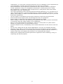
WARNING: This product is part of a personal fall arrest system. These
instructions must be provided to the user and rescuer (see section 8
Terminology). The user must read and follow the manufacturer’s
instructions for each component of the system. The user must
read and understand these instructions before using this product.
Manufacturer’s instructions must be followed for proper use and
maintenance of this product. Alteration or misuse of this product, or
failure to follow instructions may result in serious injury or death.
IMPORTANT: If you have questions about the use, care, or suitability
of this equipment for your application contact DBI‑SALA.
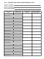
IMPORTANT: Before using this equipment record the product
identication information from the ID label in the inspection and
maintenance log in section 10.0 of this manual.
DESCRIPTIONS
TALON 8 FT (2.4 M) SERIES SELF RETRACTING LIFELINE: See
Figure 1. Includes quick connect anchorage attachment handle
and 8 foot (2.4 m) nylon web lifeline or order picker anchorage
attachment handle and 8 foot nylon web lifeline.
TALON 16 FT (4.9 M)SERIES SELF RETRACTING LIFELINE: See
Figure 2. Includes swivel eye anchorage attachment and 16 foot
(4.9 m) nylon web lifeline.
1.0 APPLICATIONS
1.1 PURPOSE: DBI-SALA self retracting lifelines (SRL’s) are
components of a personal fall arrest system (PFAS). These
SRL’s may be used where worker mobility and fall protection are
required.
FALL PROTECTION: The SLR is used as part of a complete
personal fall arrest system. Personal fall arrest systems typically
include a full body harness, anchorage connector, and SRL.
1.2 LIMITATIONS
D. CAPACITY:
The SRL is designed for use by persons with a
combined weight (clothing, tools) of no more than 310 lbs.
(141 kg). No more than one person may be connected to the
SRL at any time.
E. LOCKING SPEED: Use of the SRL in confined spaces, on
slowly shifting material (sand or grain), or on a low pitched
roof may not allow sufficient lock-up speed to arrest a fall. A
clear fall path is required to safely arrest a fall.
F. NORMAL OPERATION: Normal operation will allow the full
length of the lifeline to extend and retract without hesitation or
creating a slack line condition as the worker moves at normal

7
speeds. If a fall occurs, a speed sensing brake system will
activate, stopping the fall and absorbing much of the energy
created. If a fall has been arrested, the SRL must be removed
from service and inspected. See section 5.0. Sudden or quick
movements should be avoided during normal work operation
as this may cause the SRL to lock-up.
G. ENVIRONMENTAL HAZARDS: Use of the SRL in hazardous
environments may require additional precautions to reduce
the possibility of injury to the user or damage to the personal
fall arrest system. Hazards may include, but are not limited
to; heat, extreme cold, caustic or corrosive chemicals,
high voltage power lines, explosive or toxic gases, moving
machinery, sharp edges.
H. TRAINING: The SRL is intended to be installed and used by
persons trained in its application and use.
1.3 Refer to national standards, including the ANSI Z359 (.1,
.2, .3, and .4) family of standards on fall protection, ANSI
A10.32 and applicable local, state, and federal (OSHA)
requirements governing occupational safety for more
information about fall arrest.
2.0 SYSTEM REQUIREMENTS
2.1 COMPATIBILITY OF COMPONENTS: DBI-SALA equipment
is designed for use with DBI-SALA approved components and
subsystems only. Substitutions or replacements made with non-
approved components or subsystems may jeopardize compatibility
of equipment and may effect the safety and reliability of the
complete system. Personal fall arrest systems must meet
applicable local, state, and federal (OSHA) requirements. A full
body harness must be used with the Talon SRL.
2.2 COMPATIBILITY OF CONNECTORS: Connectors are considered
to be compatible with connecting elements when they have been
designed to work together in such a way that their sizes and
shapes do not cause their gate mechanisms to inadvertently open
regardless of how they become oriented. Contact DBI-SALA if you
have any questions about compatibility.
Connectors (hooks, carabiners, and D-rings) must be capable
of supporting at least 5,000 lbs. (22.2 kN). Connectors must be
compatible with the anchorage or other system components.
Do not use equipment that is not compatible. Non-compatible
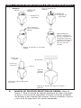
connectors may unintentionally disengage. See Figure 3.
Connectors must be compatible in size, shape, and strength. Self
locking snap hooks and carabiners are required by ANSI Z359.14
,OSHA 1926.502, and OSHA 1910.104.
2.3 MAKING CONNECTIONS: Only use self-locking snap hooks and
carabiners with this equipment. Only use connectors that are

8
suitable to each application. Ensure all connections are compatible
in size, shape and strength. Do not use equipment that is not
compatible. Ensure all connectors are fully closed and locked.
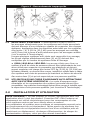
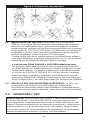
DBI-SALA connectors (snap hooks and carabiners) are designed to
be used only as specied in each product’s user’s instructions. See
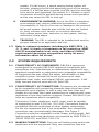
Figure 4 for inappropriate connections. DBI-SALA snap hooks and
carabiners should not be connected:
A. To a D-ring to which another connector is attached.
B. In a manner that would result in a load on the gate.
NOTE: Large throat opening snap hooks should not be connected
to standard size D‑rings or similar objects which will result in a load
on the gate if the hook or D‑ring twists or rotates. Large throat snap
hooks are designed for use on xed structural elements such as rebar
or cross members that are not shaped in a way that can capture the
gate of the hook.
C. In a false engagement, where features that protrude from the
snap hook or carabiner catch on the anchor and without visual
confirmation seems to be fully engaged to the anchor point.
D. To each other.
E. Directly to webbing or rope lanyard or tie-back (unless the
manufacturer’s instructions for both the lanyard and connector
specifically allow such a connection).
F. To any object which is shaped or dimensioned such that the
snap hook or carabiner will not close and lock, or that roll-out
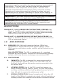
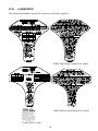
Figure 3 - Unintentional Disengagement (Roll-out)
If the connecting element that a snap hook (shown) or carabiner attaches to is undersized
or irregular in shape, a situation could occur where the connecting
element applies a
force to the gate of the snap hook or carabiner. This force may cause the gate (of either a
self-locking or a non-locking snap hook) to open, allowing the snap hook or carabiner to
disengage from the connecting point.
1. Force is applied to
the snap hook.
2. The gate presses against
the connecting ring.
3. The gate opens
allowing the snap hook
to slip off.
Small ring or other
non-compatibly
shaped element

9
could occur.
2.4 ANCHORAGE STRENGTH: In accordance with ANSI Z359.14,
anchorages selected for a fall arrest systems shall have a strength
capable of sustaining static loads applied in the directions
permitted by the system of at least: A) 5,000 pounds (22.2 kN) for
non-certied anchorages or B) Two times the maximum arresting
force for certied anchorages (see section 8 Terminology).
When more than one personal fall arrest system is attached to an
anchorage, the strengths previously set forth in (A) and (B) shall
be multiplied by the number of systems attached to the anchorage.
• From OSHA 1910.104 and 1926.502:
Anchorages
used for attachment of a personal fall arrest system shall
be independent of any anchorage being used to support or
suspend platforms, and must support at least 5,000 lbs.
(22.2 kN) per user attached, or be designed, installed, and
used as part of a complete personal fall arrest system which
maintains a safety factor of at least two, and is supervised by a
qualied person.
2.5 USING THE SRL WITH A HORIZONTAL SYSTEM: The SRL and
horizontal system components must be compatible. Horizontal
systems must be designed and installed under the supervision of a
qualied person (see section 8 Terminology).
3.0 INSTALLATION AND USE
WARNING: Do not alter or intentionally misuse this equipment.
Consult DBI‑SALA when using this equipment in combination with
components or subsystems other than those described in this manual.
Some subsystem and component combinations may interfere with the
operation of this equipment. Use caution when using this equipment
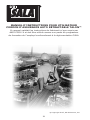
Figure 4 - Inappropriate Connections

10
around moving machinery, electrical hazards, chemical hazards, and
sharp edges.
WARNING: Consult your doctor if there is reason to doubt your
tness to safely absorb the shock from a fall arrest. Age and tness
can seriously affect your ability to withstand a fall. Pregnant women
and minors must not use this equipment.
3.1 BEFORE EACH USE: Inspect the SRL according to section 5.0.
3.2 PLAN your personal fall arrest system before installing and using
this equipment. Consider all factors affecting your safety during
use of this equipment.
A. ANCHORAGE: Select a rigid anchorage point capable of
supporting at least 5,000 lbs. (22.2 kN) See section 2.4. Select
an anchorage location that will avoid free fall and swing fall
hazards. To prevent an increased free fall distance do not work
above the anchorage.
B. FREE FALL: Your personal fall arrest system must be rigged
such that the SRL is
above your harness
attachment element
(dorsal D-ring) when
in use. Avoid working
where your lifeline may
cross or tangle with that
of another worker. Do
not allow the lifeline to
pass under your arms or
between your feet. Never
clamp, knot, or otherwise
prevent the lifeline from
retracting. Do not allow
slack in your lifeline. Do
not lengthen the SRL by
connecting a lanyard or
other component.
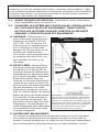
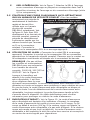
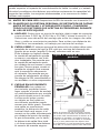
C. SWING FALLS: Swing
falls occur when the
anchorage point is not
directly above the point
where a fall occurs.
The force of striking an
object in a swing fall may
cause serious injury. In
a swing fall, the total
vertical fall distance will
be greater than if the
user had fallen directly
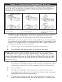
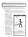
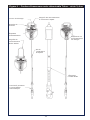
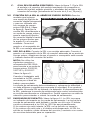
Figure 5 - Swing Falls
NOTE: The 6 ft. minimum assumes the fall
occurs from a standing position and the SRL
is located overhead. If the worker is kneeling
or crouching near an edge when a fall occurs,
and additional 3 ft. clearance is needed. If
the worker is not directly below the SRL,
additional clearance is needed.

11
below the anchorage point, thus increasing the total free fall
distance and the area required to safely arrest the user. The
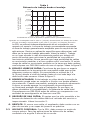
SRL will activate regardless of its orientation relative to the
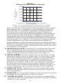
user. The recommended work zone represents the typical
acceptable work area for most applications. Review your
specific application to determine what the appropriate work
zone should be. See Chart 1. Minimize swing falls by working
as directly below the anchorage point as possible. Never
permit a swing fall if injury could occur. If a swing fall situation
exists in your application contact DBI-SALA before proceeding.
See Figure 5.
D. FALL CLEARANCE: Ensure adequate clearance exists in your
fall path to prevent striking an object. A minimum of 6 feet
from the working level to the lower level or nearest obstruction
is recommended. See Figure 5.
E. SHARP EDGES: Avoid working where the lifeline will be in
contact with or abrade against unprotected sharp edges.
Provide protection for the lifeline when possible. An energy
absorbing component can sometimes be added in-line to
further protect the worker. Compatibility and total fall distance
must be considered if this is done. Contact DBI-SALA before
using an in-line energy absorbing component or lanyard with
an SRL.
F. AFTER A FALL: Equipment which has been subjected to fall
arrest forces must be removed from service for inspection. See
section 5.
G. RESCUE: If a fall occurs, the employer must have a rescue
plan and the ability to implement a rescue.
3.3 BODY SUPPORT: A full body harness must be used with the SRL.
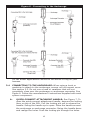
Chart 1
Working Distance From Anchorage
D=Distance person can move (horizontally)
Example: If the worker is 15 feet directly below the SRL.
The recommended work zone is 12 feet in any direction
H=Height of Talon
(Overhead)
0 ft.
0 ft.
5 ft.
10 ft.
15 ft.
20 ft.
25 ft.
5 ft.
10 ft.
15 ft. 20 ft.

12
For fall arrest applications connect to the dorsal D-ring on your
harness.
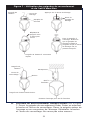
3.4 CONNECTING TO THE ANCHORAGE: When using a hook or
carabiner to attach to the anchorage, ensure roll-out cannot occur.
See section 2.3. Do not use a hook or carabiner that will not
completely close over the anchorage or anchorage connector. See
Figure 6. Follow the manufacturer’s instructions supplied with each
system component.
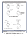
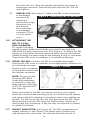
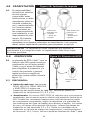
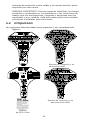
A. QUICK-CONNECT ATTACHMENT HANDLE: See Figure 7. To
open the quick-connect attachment handle, depress the locking
lever on top of the SRL. Pull the locking pin out to release the
handle. Swing the handle up to open. Place the handle around
the anchorage or anchorage connector. Swing the handle down
and realign the holes. Push the locking pin through the holes.
Figure 6 - Connecting to the Anchorage

13
Figure 7 - Using the Attachment Handles and Swivel Eye
WARNING: Ensure the locking pin fully engages the handle and the
locking lever is in the locked position.
B. ORDER PICKER ATTACHMENT HANDLE: See Figure 7.
Open the order picker attachment handle by removing the

14
bolt and lock nut. Place the handle around the anchorage or
anchorage connector. Reinstall the bolt and lock nut. Do not
over tighten.
C. SWIVEL EYE: See Figure 7. Attach the SRL to the anchorage
or anchorage
connector by
inserting a
carabiner through
the swivel eye
and around
the anchorage
or anchorage
connector [16 ft.
(4.9 m) series
only].
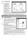
3.5 ATTACHING THE
SRL TO A FULL
BODY HARNESS:
For models including
a quick-connect attachment handle only, and to be used with
DBI-SALA full body harnesses only. See Figure 8. To attach the SRL
directly to a full body harness, pass the quick-connect attachment
handle through the same loops as the existing D-ring or connector.
Connect the SRL hook or carabiner to a suitable anchorage.
3.6 USING THE SRL: Connect the SRL to a suitable anchorage.
Connect the SRL hook or carabiner to the appropriate connector on
your full body harness.
Ensure hook or carabiner
is closed and locked onto
the harness connector.
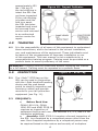
NOTE: Do not use the
following DBI-SALA
hooks and carabiners
to connect to your full
body harness: 2000108,
2007153, and 9510057.
See Figure 9.
When connected to the SRL the worker is free to move about
within the recommended working area. The lifeline should extend
and retract without hesitation or creating a slack line condition as
speeds. If a fall occurs the SRL will lock and arrest the fall. When
disconnecting from the SRL keep the lifeline under control as it
recoils back into the device. A tag line may be required to extend
or retract the lifeline.
3.7 IMPACT INDICATOR: See Figure 10. The SRL incorporates an
impact indicator in the lifeline. The lifeline web is folded over
and stitched with red thread. The stitched fold will pull out at
Figure 9 - Hooks
Figure 8 - Attaching SRL to Harness

15
approximately 450
lbs. (204 kg) If
the red stitching is
intact the SRL has
not been impacted.
If the red stitching
is broken and the
fold torn apart,
the SRL has been
impacted and must
be removed from
service and returned
to an authorized
service center for
repair.
4.0 TRAINING
4.1 It is the responsibility of all users of this equipment to understand
these instructions, and to be trained in the correct installation,
use, and maintenance of this equipment. These individuals must
be aware of the consequences of improper installation or use
of this equipment. This user manual is not a substitute for a
comprehensive training program. Training must be provided on a
periodic basis to ensure prociency of the users.
WARNING: Training must be conducted without exposing the trainee
to a fall hazard. Training must be repeated on a periodic basis.
5.0 INSPECTION
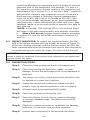
5.1 The i-Safe™ RFID tag on this
SRL can be used in conjunction
with the i-Safe handheld reading
device and the web based
portal to simplify inspection and
inventory control and provide
records for your fall protection
equipment (see Fig. 11).
5.2 FREQUENCY:
• Before Each Use:
OSHA 1910.104, OSHA
1926.502 and ANSI Z359.14
requires an inspection of
equipment before each use. See sections 5.2, 5.3, and 5.4 for
inspection guidelines.
• Annually: ANSI Z359.14 requires a formal inspection of
the SRL be completed by a competent person other than the
user. More frequent inspections by a competent person may
be required based on the nature and severity of workplace
Figure 10 - Impact Indicator
Figure 11 - RFID Tag
i-Safe RFID
Tag

16
conditions affecting the equipment and the modes of use and
exposure time of the equipment. See sections, 5.3, and 5.4
for inspection guidelines. Record results in the inspection and
maintenance log in section 10.0, or use the i-Safe™ inspection
web portal to maintain your inspection records. If you are a
rst-time user, contact a Customer Service representative
in the US at 800-328-6146 or in Canada at 800-387-7484
or if you have already registered, go to: www.capitalsafety.
com/isafe.html. Follow instructions provided with your i-Safe
handheld reader or on the web portal to transfer your data to
your web log.
*NOTE: In Canada, CSA requires SRLs to be serviced within
two years of the manufactured date, and annually thereafter.
• After a Fall Arrest: Inspect impact indicator according
to section 5.3, and the entire SRL according to sections 5.4
and 5.5.
5.3 IMPACT INDICATOR: To inspect the impact indicator, nd the
fold in the lifeline stitched with red thread, as shown in Figure 10.
If the red stitching is broken and the fold torn apart, the SRL has
been impacted and must be removed from service and returned to
an authorized service center for repair. Do not re-stitch the fold.
WARNING: If the SRL has been subjected to fall arrest or impact
forces it must be removed from service and returned to an authorized
service center for repair.
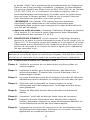
5.4 INSPECTION STEPS:
Step 1. Check for loose screws and bent or damaged parts.
Step 2. Check the housing for distortion, cracks, or other
damage. Ensure the anchorage point is not damaged or
distorted.
Step 3. The lifeline must fully extend and retract smoothly with
no hesitation or slack line condition.
Step 4. Ensure the device locks when the lifeline is pulled
sharply. Lock-up should be positive, with no slipping.
Step 5. All labels must be present and fully legible.
Step 6. Check for corrosion on the entire unit.
Step 7. Check the lifeline for cuts, burns, chemical damage,
or severely abraded areas. The lifeline must not be
damaged.
Step 8. Check the connecting hooks or carabiners for damage,
distortion, or corrosion, and working condition.
Step 9. Inspect each component of the personal fall arrest

17
system according to manufacturer’s instructions.
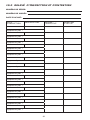
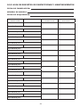
Step 10. Record the inspection results in the inspection and
maintenance log in section 10.0 or using the I-safe web
portal.
5.5 If the inspection reveals an unsafe or defective condition, remove
the SRL from service and contact an authorized service center for
repair.
NOTE: Only DBI‑SALA or parties authorized in writing may make
repairs to this equipment.
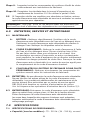
6.0 MAINTENANCE, SERVICING, AND STORAGE
6.1 MAINTENANCE:
A. HOUSING: Periodically clean the exterior of the SRL with
water and a mild detergent. Position the SRL so water
can drain out. Clean the labels as required.
B. LIFELINE: Clean the lifeline with water and a mild detergent.
Rinse and thoroughly air dry. Do not force dry with heat. An
excessive build-up of dirt or other contaminants may prevent
the lifeline from fully retracting, causing a potential free fall
hazard. Return the SRL to an authorized service center for
lifeline replacement if necessary.
C. PERSONAL FALL ARREST SYSTEM COMPONENTS: Clean
and store associated system components according to
manufacturer’s instructions.
6.2 SERVICING: Do not disassemble the SRL. Do not lubricate any
part of the SRL. Additional maintenance and servicing must be
performed by an authorized service center. A return authorization
number must be issued by DBI-SALA. See section 5.2 for servicing
frequency.
6.3 STORAGE: Store the SRL in a cool, dry, and clean environment,
out of direct sunlight. Avoid storing the SRL in areas where
chemical vapors exist. Thoroughly inspect the SRL after extended
storage.
7.0 SPECIFICATIONS
7.1 PERFORMANCE SPECIFICATIONS:
• Capacity (All Models): 75 - 310 lbs. (34 - 141 kg), one
user only
• Working Range, 8 Foot Models:
2.5 ft. - 8 ft (.8 m - 2.4 m)
• Working Range, 16 Foot Models:
1.5 ft. - 16 ft (.5 m - 4.9 m)
• Maximum Arresting Force (All Models)
: 1,350 lbs.
(612 kg)
when tested in accordance with ANSI Z359.14.

18
•
Average Locking Speed (All Models):
4.5 ft./sec. (1.4 m / sec.)
• Maximum Arresting Distance (All Models): 42 in. (1 m)
7.2 PHYSICAL SPECIFICATIONS:
8 FOOT MODELS:
• Overall Dimensions, Quick-Connect Attachment Handle
Models (LxWxH): 6.7 x 3.9 x 2.2 in. (17 cm x 10 cm x 6 cm)
• Overall Dimensions, Order Picker Attachment Handle
Models (LxWxH): 8.9 x 3.9 x 2.2 in. (23 cm x 10 cm x 6 cm)
16 FOOT MODELS:
Overall Dimensions (LxWxH): 7.9 x 5.9 x 2.4 in. (20 cm x 15 cm x 6 cm)
ALL MODELS:
Materials:
Housing: Nylon
Cable Drum: Glass lled nylon
Internal Components: Steel/Aluminum
Lifeline: 3/4 inch nylon web
7.3 PATENTS AND REQUIREMENTS:
• Patents Pending
• Meets Z359.14 Class B, OSHA 1926.502, and OSHA
1910.140.
8.0 TERMINOLOGY
AUTHORIZED PERSON: A person assigned by the employer to perform
duties at a location where the person will be exposed to a fall hazard
(otherwise referred to as “user” for the purpose of these instructions).
RESCUER: Person or persons other than the rescue subject acting to
perform an assisted rescue by operation of a rescue system.
CERTIFIED ANCHORAGE: An anchorage for fall arrest, positioning,
restraint, or rescue systems that a qualified person certifies to be capable
of supporting the potential fall forces that could be encountered during
a fall or that meet the criteria for a certified anchorage prescribed in this
standard.
QUALIFIED PERSON: A person with a recognized degree or professional
certificate and with extensive knowledge, training, and experience in the
fall protection and rescue field who is capable of designing, analyzing,
evaluating and specifying fall protection and rescue systems to the extent
required by this standard.
COMPETENT PERSON: One who is capable of identifying existing and
predictable hazards in the surroundings or working conditions which
are unsanitary, hazardous, or dangerous to employees, and who has
authorization to take prompt corrective measures to eliminate them.

19
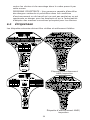
ANSI Warning/Inspection Label
9.0 LABELING
i-Safe RFID Label
The following labels must be present and fully legible:
ANSI Warning/Inspection Label

20
MANUEL D’INSTRUCTIONS POUR UTILISATEUR
CORDON D’ASSURANCE AUTO RÉTRACTABLE TALON™
Ce manuel satisfait les instructions du fabricant tel que requis par
ANSI Z359.14 et doit être utilisé comme une partie du programme
de formation de l’employé conformément à la réglementation OSHA.
© Copyright 2007, DB Industries, Inc.
La page est en cours de chargement...
La page est en cours de chargement...
La page est en cours de chargement...
La page est en cours de chargement...
La page est en cours de chargement...
La page est en cours de chargement...
La page est en cours de chargement...
La page est en cours de chargement...
La page est en cours de chargement...
La page est en cours de chargement...
La page est en cours de chargement...
La page est en cours de chargement...
La page est en cours de chargement...
La page est en cours de chargement...
La page est en cours de chargement...
La page est en cours de chargement...
La page est en cours de chargement...
La page est en cours de chargement...
La page est en cours de chargement...
La page est en cours de chargement...
La page est en cours de chargement...
La page est en cours de chargement...
La page est en cours de chargement...
La page est en cours de chargement...
La page est en cours de chargement...
La page est en cours de chargement...
La page est en cours de chargement...
La page est en cours de chargement...
La page est en cours de chargement...
La page est en cours de chargement...
La page est en cours de chargement...
La page est en cours de chargement...
La page est en cours de chargement...
La page est en cours de chargement...
La page est en cours de chargement...
La page est en cours de chargement...
La page est en cours de chargement...
La page est en cours de chargement...
La page est en cours de chargement...
La page est en cours de chargement...
La page est en cours de chargement...
La page est en cours de chargement...
La page est en cours de chargement...
La page est en cours de chargement...
-
 1
1
-
 2
2
-
 3
3
-
 4
4
-
 5
5
-
 6
6
-
 7
7
-
 8
8
-
 9
9
-
 10
10
-
 11
11
-
 12
12
-
 13
13
-
 14
14
-
 15
15
-
 16
16
-
 17
17
-
 18
18
-
 19
19
-
 20
20
-
 21
21
-
 22
22
-
 23
23
-
 24
24
-
 25
25
-
 26
26
-
 27
27
-
 28
28
-
 29
29
-
 30
30
-
 31
31
-
 32
32
-
 33
33
-
 34
34
-
 35
35
-
 36
36
-
 37
37
-
 38
38
-
 39
39
-
 40
40
-
 41
41
-
 42
42
-
 43
43
-
 44
44
-
 45
45
-
 46
46
-
 47
47
-
 48
48
-
 49
49
-
 50
50
-
 51
51
-
 52
52
-
 53
53
-
 54
54
-
 55
55
-
 56
56
-
 57
57
-
 58
58
-
 59
59
-
 60
60
-
 61
61
-
 62
62
-
 63
63
-
 64
64


dans d''autres langues
- English: DBI-SALA 3101000 User manual
- español: DBI-SALA 3101000 Manual de usuario
Documents connexes
Autres documents
-
3M DBI-SALA® Swiveling Roof Anchor 2190071, 1 EA Mode d'emploi
-
-
-
-
Honeywell Miller MightEvac User Instruction Manual
-
-
-
-
3M 3900109 Mode d'emploi
-