
WARNING
If the information in this manual is not
followed exactly, a fire or explosion may
result causing property damage, personal
injury or loss of life.
Do not store or use gasoline or other
flammable vapors and liquids in the vicinity of
this or any other appliance.
WHAT TO DO IF YOU SMELL GAS
• Do not try to light any appliance.
• Do not touch any electrical switch; do not
use any phone in your building.
• Immediately call your gas supplier from
a nearby phone. Follow the gas supplier's
instructions.
• If you cannot reach your gas supplier, call
the fire department.
Installation and service must be performed
by a qualified installer, service agency, or gas
supplier.
Installation and Operation Instructions Document 1231D
H2358000D
FOR YOUR SAFETY: This product must be installed and serviced by a professional service technician,
qualified in hot water boiler installation and maintenance. Improper installation and/or operation could
create carbon monoxide gas in flue gases which could cause serious injury, property damage, or
death. Improper installation and/or operation will void the warranty. For indoor installations, as an
additional measure of safety, Laars strongly recommends installation of suitable Carbon Monoxide
detectors in the vicinity of this appliance and in any adjacent occupied spaces.
AVERTISSEMENT
Assurez-vous de bien suivres les instructions
données dans cette notice pour réduire au
minimum le risque d’incendie ou d’explosion ou
pour éviter tout dommage matériel, toute blessure
ou la mort.
Ne pas entreposer ni utiliser d’essence ni d’autres
vapeurs ou liquides inflammables dans le voisinage
de cet appareil ou de tout autre appareil.
QUE FAIRE SI VOUS SENTEZ UNE ODEUR DE GAZ:
• Ne pas tenter d’allumer d’appareils.
• Ne touchez à aucun interrupteur. Ne pas vous
servir des téléphones dansle bâtiment où vous
trouvez.
• Appelez immédiatement votre fournisseur de
gaz depuis un voisin. Suivez les instructions
du fournisseur.
• Si vous ne pouvez rejoindre le fournisseur de
gaz, appelez le sservice des incendies.
L’installation et l’entretien doivent être assurés par
un installateur ou un service d’entretien qualifié ou
par le fournisseur de gaz.
Installation and Operation
Instructions for
MIGHTY THERM2
®
Hydronic Boiler
Model MT2H
Water Heater
Model MT2V
Sizes 200, 300, 400

LAARS Heating Systems
Page 2
TABLE OF CONTENTS
SECTION 1 General Information ...............3
1.A Introduction ................................................ 3
1.B Model Identication .................................... 4
1.C Warranty .................................................... 4
1.D Dimensions ................................................ 4
1.E Locating the Appliance............................... 4
1.F Locating Pump-Mounted Water Heater
with Respect to Storage Tank(s) ................ 7
1.G Locating Pump-Mounted Boiler with
Respect to Return/Supply Header ............. 7
1.H Locating Appliance for Correct Horizontal
Vent/Ducted Air Distance
From Outside Wall ..................................... 7
SECTION 2 Venting and Combustion Air .8
2.A Combustion Air .......................................... 8
2.A.1 Combustion Air From Room ...................... 8
2.A.2 Intake Combustion Air................................ 9
2.B Venting ....................................................... 9
2.B.1 Vent Categories ......................................... 9
2.B.2 Category I Vent .......................................... 9
2.B.3 Common Venting Systems ........................ 9
2.B.4 Category III Vent ...................................... 10
2.C Locating Vent & Combust Air Terminals ... 10
2.C.1 Side Wall Vent Terminal ........................... 10
2.C.2 Side Wall Combustion Air Terminal .......... 13
2.C.3 Vertical Vent Terminal .............................. 13
2.C.4 Vertical Combustion Air Terminal ............. 13
2.D Common Vent Test — Boilers .................. 13
2.E Vent Terminals for Outdoor Units ............. 14
SECTION 3 Gas Supply and Piping .......15
3.A Gas Supply and Piping ............................ 15
SECTION 4 Water Connections — .........16
4.A Mighty Therm2 Boiler ............................... 16
4.A.1 Heating System Piping:
Hot Supply Connections — Boiler ........... 16
4.A.2 Cold Water Make-Up — Boiler ................ 16
4.A.3 Water Flow Requirements — Boiler ........ 16
4.A.4 Freeze Protection — Boiler...................... 16
4.B Water Connections — Mighty Therm2
Water Heater ........................................... 17
4.B.1 Water System Piping — Water Heater .... 17
4.B.2 Hot Water Supply Piping —Water Heater 20
4.B.3 Water Flow Requirements — .......................
Water Heater ........................................... 20
4.B.4 Combined Water Heating (potable)
and Space Heating — Water Heater ....... 20
4.B.5 Freeze Protection — Water Heater ......... 20
SECTION 5 Electrical Connections ........24
5.A Main Power .............................................. 24
5.B Field Wiring .............................................. 24
5.C Low Water Cut-O ................................... 24
5.C Logic Diagrams ........................................ 25
5.C Wiring Diagrams ...................................... 26
SECTION 6 Operating Instructions ........28
6.A Filling the Boiler System .......................... 28
6.B Operating Temperature Control ............... 28
6.B.1 Temp Control on Boilers .......................... 29
6.B.2 Temp Control on Water Heaters .............. 30
6.C External Boiler Operations ....................... 30
6.D Sequence of Operation ............................ 31
6.E Ignition Control Reaction to Air Flow
/ Blocked Vent Pressure Switch ............... 31
6.F Operating the Burner and Set-Up ............ 31
6.F.1 Set-Up for 0 to 2500 Feet Altitude ........... 31
6.F.2 High Altitude Adjustment and Set-Up....... 32
6.G Shutting Down the Mighty Therm2 .......... 33
6.H To Restart the Mighty Therm2 ................. 33
SECTION 7 Maintenance ......................... 33
7.A System Maintenance ............................... 33
7.B Appliance Maintenance and Component
Description ............................................... 33
7.B.1 Burners .................................................... 34
7.B.2 Filter ......................................................... 34
7.B.3 Gas Valves ............................................... 34
7.B.4 Manual Reset High Limit Control ............. 34
7.B.5 Ignition Control......................................... 34
7.B.6 Ignitor ....................................................... 34
7.B.7 Transformer ............................................. 35
7.B.8 Flow Switch .............................................. 35
7.B.9 Heat Exchanger Coil ............................... 35
SECTION 8 Trouble Shooting ..................36
8.A Resolving Lockouts.................................. 36
8.B Delayed Ignition — Possible Causes....... 36
8.C Short Cycling — Boiler............................. 36
8.D Short Cycling — Water Heater ................ 36
8.E High Gas Consumption............................ 36
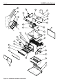
SECTION 9 Replacement Parts ...............37
9.A General Information ................................. 37
9.B Parts List .................................................. 37

Mighty Therm2 (200, 300, 400)
Page 3
SECTION 1 General Information
USING THIS MANUAL – Because the Mighty
Therm2 Boilers and Mighty Therm2 Water Heaters
are identical appliances, with the exception of
materials of manufacture, labels and ultimate use
application, this manual provides information
for the proper installation, operation and
maintenance of both products. Where dierences
exist between the application of the appliances and
their operation, the sections pertinent to only one
appliance or the other will be so identied.
In the Commonwealth of Massachusetts, this
appliance must be installed by a licensed plumber or
gas tter.
1.A Introduction
This manual provides information necessary
for the installation, operation, and maintenance of
Laars Heating Systems’ Mighty Therm2 copper tube
appliances, sizes 200-400 MBTU/hr (larger models are
covered in a separate manual). Read it carefully before
installation.
All application and installation procedures
should be reviewed completely before proceeding with
the installation. Consult the Laars Heating Systems
factory, or local factory representative, with any issues
or questions regarding this equipment. Experience
has shown that most operating issues are caused by
improper installation.
The Mighty Therm2 appliance is protected
against over pressurization. A pressure relief valve
is tted to all appliances. It is installed on the outlet
header, at the water outlet of the appliance.
IMPORTANT: The inlet gas pressure to the appliance
must not exceed 13 in. w.c. (3.2 kPa) for Natural Gas
and 10.5 in. w.c. (2.5 kPa) for LP. See "Table 11. Gas
Pressure in inches (w.c.)" on page 32.
All installations must be made in accordance with:
1) In the U.S., the " National Fuel Gas Code "ANSI
Z223.1/NFPA54, Latest Edition and all applicable
local codes as required by the Authorities Having
Jurisdiction (AHJ), or
2) In Canada, the "Natural Gas and Propane
Installation Code", CSA B149.1, latest edition and all
applicable local codes as required by the AHJ.
All electrical wiring is to be done in accordance with:
1). In the U.S., the "National Electrical Code" (NEC),
ANSI/NFPA 70, latest Edition and all applicable local
codes as required by the AHJ, or
2). In Canada, the “Canadian Electrical Code - Part
1”, CSA STD. C22.1 and all applicable local codes as
required by the AHJ.
This appliance must be electrically grounded in
accordance with the applicable codes and standards
referenced above.
WARNING
To minimize the risk of electric shock, fire or
other hazards which could result in property
damage, injury, or death. The Mighty Therm2
hydronic, boiler or water heater must be
installed in accordance with the procedures
detailed in this manual, or the Laars Heating
Systems warranty may be voided. The
installation must conform to the requirements
of the local jurisdiction having authority, and,
in the United States, to the latest edition of the
National Fuel Gas Code, ANSI Z223.1/NFPA54.
In Canada, the installation must conform
to the latest edition of the Natural Gas and
Propane Installation Code, CSA B149.1 and/
or applicable local codes. Where required by
the authority having jurisdiction, the installation
of Mighty Therm2 appliances must conform to
the Standard for Controls and Safety Devices
for Automatically Fired Boilers, ANSI/ASME
CSD-1. Any modifications to the boiler, its gas
controls, or wiring may void the warranty. If
field conditions require modifications, consult
the factory representative before initiating such
modifications.
AVERTISSEMENT
Afin de minimiser les risques d'électrocution,
d'incendie ou d'autres dangers qui pourraient
entraîner des dommages aux biens, des
blessures ou la mort. Le Mighty Therm2
hydronique, une chaudière ou un chauffe-eau
doit être installé conformément aux procédures
détaillées dans ce manuel, ou le chauffage
Laars Systèmes garantie peut être annulée.
L'installation doit être conforme aux exigences
de la juridiction locale ayant l'autorité, et, aux
ÉTATS-UNIS , à la dernière édition du National
gaz combustible Code, ANSI Z223.1/NFPA54.
Au Canada, l'installation doit être conforme à
la dernière édition du gaz naturel et propane
Code d'Installation, CSA B149.1 et/ou codes
locaux. Lorsque requis par l'autorité ayant
juridiction, l'installation de Mighty Therm2 les
appareils doivent être conformes à la norme
pour les contrôles et les dispositifs de sécurité
automatiquement pour chaudières, ANSI/ASME
LA CDD-1. Toute modification apportée à la
chaudière, de ses commandes de gaz, ou le
câblage peut annuler la garantie.

LAARS Heating Systems
Page 4
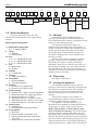
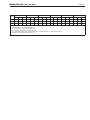
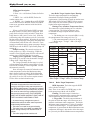
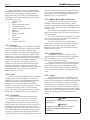
1.B Model Identication
Consult the rating plate on the unit. The
following information describes the model number
structure.
Model Character Designation
1-3 Model Series Designation
M T 2 = Mighty Therm2
4 Usage
H = Hydronic
V = Volume Water
5-8 Size
0 2 0 0 = 199,900 BTU/h input
0 3 0 0 = 300,000 BTU/h input
0 4 0 0 = 399,900 BTU/h input
9 Fuel
N = Natural Gas
P = Propane
10 Altitude
A = 0-10,000 feet
11 Location
C = Indoor and Outdoor
12 Firing Mode
C = On-O (standard)
K = Two-stage (optional)
13 Revision
2 = Revision Level 2 (MT2H only)
3 = Revision Level 3 (MT2V only)
14 Heat Exchanger
B = Glass-lined CI / copper / brz trim (std. MT2V)
C = Glass-lined cast iron / copper (std. MT2H)
N = Glass-lined cast iron / cu-nickel
P = Glass-lined cast iron / cu-nickel / brz trim
2 = Glass-lined cast iron / copper, brz trim, HLW
5 = Glass-lined cast iron / cu-nickel / brz, HLW
15 Options Code
X = Standard unit
L = Low temperature control (std. MT2V)
16 Pump Options
X = No Pump
N = Pump mounted, normal water, Taco
S = Pump mounted, soft water pump (MT2V
only), Taco
G = Pump mounted, normal water, Grundfos
1.C Warranty
Laars Heating Systems’ Mighty Therm2
appliances are covered by a limited warranty. The
owner should ll out the warranty registration card and
return it to Laars Heating Systems.
All warranty claims must be made to an
authorized Laars Heating Systems representative or
directly to the factory. Claims must include the serial
number and model (this information can be found
on the rating plate), installation date, and name of
the installer. Shipping costs are not included in the
warranty coverage.
Some accessory items are shipped in separate
packages. Verify receipt of all packages listed on
the packing slip. Inspect everything for damage
immediately upon delivery, and advise the carrier of
any shortages or damage. Any such claims should be
led with the carrier. The carrier, not the shipper, is
responsible for shortages and damage to the shipment
whether visible or concealed.
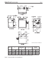
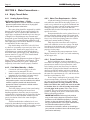
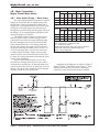
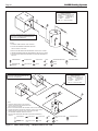
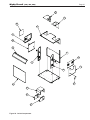
1.D Dimensions
See Figure 1 and Figure 2
1.E Locating the Appliance
The appliance should be located to provide
clearances on all sides for maintenance and inspection.
It should not be located in an area where leakage of
any connections will result in damage to the area
adjacent to the appliance or to lower oors of the
structure.
When such a location is not available, it is
recommended that a suitable drain pan, adequately
drained, be installed under the appliance.
The appliance is design certied by CSA-
International for installation on combustible ooring;
in basements; in closets, utility rooms or alcoves.
Mighty Therm2 Boilers or Water Heaters must
never be installed on carpeting. The location for the
appliance should be chosen with regard to the vent
pipe lengths and external plumbing. The unit shall be
installed such that the gas ignition system components
are protected from water (dripping, spraying, rain, etc.)
during operation and service (circulator replacement,
control replacement, etc.). When vented vertically, the
1 2 3 4 5 6 7 8 9 10 11 12 13 14 15 16
M T 2 A C
SERIES
M T 2
USAGE
H
V
SIZE
0 2 0 0
0 3 0 0
0 4 0 0
FUEL
N
P
ALTITUDE
A
FIRING
MODE
C
K
LOCATION
C
REVISION
2
3
HEAT
EXCHANGER
B
C
N
P
2
5
OPTIONS
CODE
X
L
PUMP
OPTIONS
X
N
S
G

Mighty Therm2 (200, 300, 400)
Page 5
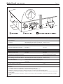
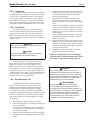
Figure 1. Dimensional Data - Non Pump Mounted.
*Air and vent connections may be on top or back of the Mighty Therm2, and are eld convertible.
Model A
Combustion Air
Connection
B*
Vent Connection
C*
Horizontal
(Cat III)
Vent Pipe Size
in. cm in. cm in. cm in. cm
200 20.5 52 4 10 5 13 4 10
300 26.5 67 4 10 6 15 5 13
400 33.6 85 6 15 7 18 6 15
Dimensions shown in inches, cm.

LAARS Heating Systems
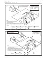
Page 6
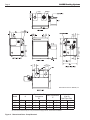
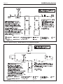
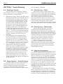
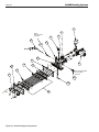
Figure 2. Dimensional Data - Pump Mounted.
*Air and vent connections may be on top or back of the Mighty Therm2, and are eld convertible.
Model A
Combustion Air
Connection
B*
Vent Connection
C*
Horizontal
(Cat III)
Vent Pipe Size
in. cm in. cm in. cm in. cm
200 20.5 52 4 10 5 13 4 10
300 26.5 67 4 10 6 15 5 13
400 33.6 85 6 15 7 18 6 15
Dimensions shown in inches, cm.

Mighty Therm2 (200, 300, 400)
Page 7
Mighty Therm2 must be located as close as practical
to a chimney or outside wall. If the vent terminal
and/or combustion air terminal terminate through a
wall, and there is potential for snow accumulation in
the local area, both terminals should be installed at an
appropriate level above grade such that blockage of
the terminal from accumulated debris or precipitation
is prevented.
The dimensions and requirements that are shown
in Table 2 should be met when choosing the locations
for the appliance.
1.F Locating Pump-Mounted Water
Heater with Respect to Storage Tank(s)
For best results, a pump-mounted Mighty
Therm2 water heater should be located within 15 feet
(4.6m) of the storage tank(s). The pump is sized for 30
feet (9.1m) of piping.
If the appliance must be installed with longer
piping runs, then larger diameter pipe or tubing may be
acceptable. Consult the factory for assistance.
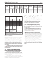
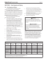
Heater
Size
Vent Collar
Size
Horizontal
Vent Pipe
Diameter
Intake
Air Collar
& Pipe
Diameter
Max. Pipe
Length
Max. No.
of Elbows
Side Vent
Terminal
Part Number
Side Wall
Combustion
Air Terminal
Part Number
in cm in cm in cm ft m
200 5 13 4 10 4 10 50 15 3 CA003101 CA003201
300 6 15 5 13 4 10 50 15 3 CA003102 CA003201
400 7 18 6 15 6 15 50 15 3 CA003103 CA003202
Table 1. Horizontal Vent / Combustion Air Parameters.
Appliance
Surface
Required
Clearance From
Combustible Material
Recommended
Service Access
Clearance
inches cm inches cm
Left Side 1 2.5 24 61
Right Side 1 2.5 24 61
Top 1 2.5 12 30
Back 1 2.5 12** 30**
Front 1 2.5 36 91
Vertical
(Category 1)
Vent
6* 15.2*
Horizontal
(Category 3)
Vent
per UL 1738 venting
system supplier's
instructions
*1" (2.5 cm) when b-vent is used.
**When vent and/or combustion air connects to the back,
recommended clearance is 36" (91cm).
Table 2. Clearances.
1.G Locating Pump-Mounted Boiler with
Respect to Return/Supply Header
For the best results, a pump-mounted unit must
be installed within 15 feet (4.6m) of supply and return
manifolds or tanks.
If the appliance must be installed with longer
piping runs, then larger diameter tubing may be
acceptable. Consult the factory for assistance.
1.H Locating Appliance for Correct
Horizontal Vent/Ducted Air Distance From
Outside Wall
The forced draft combustion air blower in the
appliance has sucient power to pull air and vent
properly when the guidelines for horizontal air and
vent are followed (see Table 1).
NOTE: On some models, the vent collar size is
larger than the size of the vent pipe that can be
used. Vent collar size and horizontal pipe diameters
can be found in Table 1 The larger vent collar size is
to accommodate Category I (vertical) vent systems.
NOTE: When located on the same wall, the Mighty
Therm2 combustion air intake terminal must be
installed a minimum of 12" (30cm) below the
exhaust vent terminal and separated by a minimum
of 36 inches (91cm) horizontally.
The air intake terminal must be installed high
enough to avoid blockage from snow, leaves and other
debris.

LAARS Heating Systems
Page 8
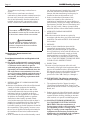
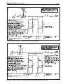
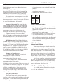
Figure 3. Combustion Air and Vent Through Roof.
SECTION 2 Venting and
Combustion Air
WARNING
For indoor installations, as an additional
measure of safety, National Combustion Co.
strongly recommends installation of suitable
Carbon Monoxide detectors in the vicinity of this
appliance and in any adjacent occupied spaces.
AVERTISSEMENT
Pour des installations intérieures, National
Combustion Co. recommande fortement, comme
mesure de sécurité supplémentaire, l’installation
de détecteurs de monoxyde de carbone adaptés
dans le voisinage de l’appareil et dans chacune
des pièces habitées adjacentes.
2.A Combustion Air
Mighty Therm2 boilers and water heaters must
have provisions for combustion and ventilation air in
accordance with the applicable sections addressing
requirements for air for combustion and ventilation of
the National Fuel Gas Code, ANSI Z223.1. In Canada,
the applicable sections of the Natural Gas and Propane
Installation Code (CSA B149.1) must be followed. In
all cases any and all applicable local installation codes
must also be followed.
A Mighty Therm2 appliance may receive
combustion air from the space in which it is installed,
or it can be ducted directly to the unit from the outside.
Proper ventilation air must be provided in either case.
2.A.1 Combustion Air From Room
In the United States, the most common
requirements specify that the space shall communicate
with the outdoors in accordance with method 1 or 2,
which follow. Where ducts are used, they shall be of
the same cross-sectional area as the free area of the
openings to which they connect.
Method 1: Two permanent openings, one
commencing within 12 inches (30 cm) of the top
and one commencing within 12 inches (30 cm) of
the bottom, of the enclosure shall be provided. The
openings shall communicate directly, or by ducts,
with the outdoors or spaces that freely communicate
with the outdoors. When directly communicating
with the outdoors, or when communicating to the
outdoors through vertical ducts, each opening shall
have a minimum free area of 1 square inch per 4000
Btu/hr (5.5 square cm/kW) of total input rating of all
equipment in the enclosure. When communicating to
the outdoors through horizontal ducts, each opening
shall have a minimum free area of not less than
1 square inch per 2000 Btu/hr (11 square cm/kW) of
total input rating of all equipment in the enclosure.
Table 1 shows data for this sizing method, for each
Mighty Therm2 model.
Method 2: One permanent opening, commencing
within 12 inches (30 cm) of the top of the enclosure,
shall be permitted. The opening shall directly
communicate with the outdoors or shall communicate
through a vertical or horizontal duct to the outdoors
or spaces that directly communicate with the outdoors
and shall have a minimum free area of 1 square inch
per 3000 Btu/hr (7 square cm/kW) of the total input
rating of all equipment located in the enclosure. This
opening must not be less than the sum of the areas of
all vent connectors in the conned space.
Other methods of introducing combustion and
ventilation air are acceptable, providing they conform
to the requirements in the applicable codes listed
above.
In Canada, consult local building and safety
codes or, in absence of such requirements, follow CSA
B149.1, the Natural Gas and Propane Installation Code.
Boiler
Model
Each Opening*
Square inches Square cm
200 50 323
300 75 484
400 100 645
*Net Free Area in Square Inches / Square cm
Area indicated is for one of two openings; one at oor level
and one at the ceiling, so the total net free area could be
double the gures indicated.
This chart is for use when communicating directly with the
outdoors. For special conditions and alternate methods, refer
to the latest edition of ANSI Z223.1.
Note: Check with louver manufacturers for net free area of
louvers. Correct for screen resistance to the net free area
if a screen is installed. Check all local codes applicable to
combustion air.
Table 3. Combustion Air Openings.

Mighty Therm2 (200, 300, 400)
Page 9
2.B Venting
2.B.1 Vent Categories
Depending upon desired Mighty Therm2 venting,
it may be considered a Category I or a Category III
appliance. In general, a vertical vent system will
be a Category I system. However, in rare instances,
a Mighty Therm2’s vertical vent system may be
considered Category III. In the U.S., the National Fuel
Gas Code (ANSI Z223.1), or in Canada the Natural
Gas and Propane Installation Code (CSA B149.1),
denes a Category I vent system, and includes rules
and tables to size these vent systems. If the Mighty
Therm2’s vertical vent system does not satisfy the
criteria for Category I venting, it must be vented as a
Category III system.
All Mighty Therm2 vent systems which
discharge horizontally (without the use of a power
venter) are considered Category III vent systems.
2.B.2 Category I Vent
When vented as a Category I appliance, the
vent system must conform to the National Fuel Gas
Code (ANSI Z223.1-Latest Edition) in the U.S., or in
Canada, to the Natural Gas and Propane Installation
Code (CSA B149.1 latest edition). The vent system
must be sized and installed for a Category I Fan-
Assisted Appliance.
If chimney height is greater than 25 feet, or
if multiple units are vented into the same vertical
vent, a barometric damper must be installed on each
appliance, such that the ue draft does not exceed
(negative) 0.1 in. w.c.
If using a power venter for any type of Category
I venting, the draft should be set between (negative)
0.01 and 0.05 in. w.c.
2.B.3 Common Venting Systems
Mighty Therm2 units are Category I fan-assisted
when vented vertically and adhering to all applicable
codes. Mighty Therm2 units are not allowed to be
vented into a common horizontal vent system, unless
a properly sized vent fan is used, and the common
vent system is properly designed by the vent fan
manufacturer or a qualied engineer. When common
venting Mighty Therm2 fan-assisted unit with other
appliances through one shared vertical duct called a
“common vent”, special care must be taken by the
installer to ensure safe operation. In the event that
the common vent is blocked, it is possible, especially
for fan-assisted devices, to vent backwards through
non-operating appliances sharing the vent, allowing
combustion products to inltrate occupied spaces.
If the appliances are allowed to operate in this
condition, serious injury or death may occur.
WARNING
Operation of appliances with a blocked common
vent may lead to serious injury or death. Safety
devices must be implemented to prevent blocked
common vent operation. If safe operation of all
appliances connected to a common vent cannot
be assured, including prevention of spillage of
flue gasses into living spaces, common venting
should not be applied, and appliances should
each be vented separately.
2.A.2 Intake Combustion Air
The combustion air can be taken through the
wall, or through the roof. When taken from the wall, it
must be taken from out-of-doors by means of the Laars
horizontal wall terminal (see Table 1). When taken
from the roof, a eld-supplied rain cap or an elbow
arrangement must be used to prevent entry of rain
water (see Figure 3).
Use single-wall galvanized pipe for the
combustion air intake (see Table 1 for appropriate
size). Route the intake to the heater as directly as
possible. Seal all joints with tape. Provide adequate
hangers. The unit must not support the weight of the
combustion air intake pipe. Maximum linear pipe
length allowed is 50 feet (15.2m). Three elbows have
been calculated into the 50-foot (15.2m) linear run.
Subtract 10 allowable linear feet (3.0m) for every
additional elbow used (see Table 1). When fewer than
3 elbows are used, the maximum linear pipe length
allowed is still 50 feet (15.2m).
Term Description
Pipe Single-wall galvanized steel pipe, 24 gauge
minimum (either insulated or non-insulated)
Joint Sealing Permanent duct tape or aluminum tape
Table 3. Required Combustion Air Piping
Material.
The connection for the intake air pipe is on the
lter box. The Mighty Therm2 appliances may have
venting and combustion air ducting attached to the top
or the back. They are shipped with the connections
at the top. For attaching either or both pipes to the
back, the mounting anges are reversible by removing
the mounting screws and orienting the anges in the
desired position. Replace the screws after positioning
anges. Run a bead of silicone around the collar and
slide the pipe over the collar. Secure with sheet metal
screws.
In addition to air needed for combustion, air
shall also be supplied for ventilation, including all air
required for comfort and proper working conditions
for personnel. The Mighty Therm2 loses less than 1
percent of its input rating to the room, but other heat
sources may be present.

LAARS Heating Systems
Page 10
AVERTISSEMENT
Le fonctionnement d’appareils connectés à
un évent commun bouché peut provoquer de
sérieuses blessures corporelles ou la mort.
Des dispositifs de sécurité doivent être mis en
place pour empêcher que les appareils soient
utilisés avec un évent commun bouché. Si un
fonctionnement sécuritaire de tous les appareils
reliés à un évent commun et si la prévention des
dégagements accidentels de gaz de combustion
dans des zones habitées ne peuvent pas être
assurés, un évent commun ne doit pas être mis
en place et les appareils doivent être munis
d’évents individuels séparés.
It is for this reason that, in addition to
following proper vent sizing, construction and safety
requirements from the National Fuel Gas Code,
ANSI Z223.1 or in Canada, from the Natural Gas
and Propane Installation Code (CSA B149.1) as
well as all applicable local codes, it is required that
installers provide some means to prevent operation
with a blocked common vent. It is suggested that a
blocked vent safety system be employed such that if
the switch from one appliance trips due to excessive
stack spill or back pressure indicating a blocked vent
condition, that all appliances attached to the vent be
locked out and prevented from operating. Note that
the Mighty Therm2 is equipped with a blocked vent
safety (pressure) switch, as shipped. However, this
safety switch has only been designed and tested to be
eective in installations where the Mighty Therm2
is vented separately and NOT common vented with
other appliances. As an additional precaution, it is
recommended that a Carbon Monoxide (CO) alarm be
installed in all enclosed spaces containing combustion
appliances. If assistance is required in determining
how a blocked vent safety system should be connected
to a LAARS product, please call Applications
Engineering at the Rochester phone number on the
back cover of this manual.
Refer to the installation and operating
instructions on all appliances to be common vented
for instructions, warnings, restrictions and safety
requirements. If safe operation of all appliances
connected to a common vent cannot be assured,
including prevention of spillage of ue gases into
living spaces, common venting should not be applied,
and appliances should each be vented separately.
2.B.4 Category III Vent
When the Mighty Therm2 is vented with
horizontal discharge, it must be installed per
this installation manual and the venting system
manufacturer’s installation instructions. The vent
system must be sealed stainless steel, per Table 4.
Term Description
Pipe Must comply with UL Standard 1738 such
as Type AL29-4C Stainless Steel
(either insulated or non-insulated).
Joint
Sealing
Follow vent manufacturer's instructions.
Table 4. Required Horizontal Venting Material.
Route the vent pipe to the heater as directly as
possible. Seal all joints and provide adequate hangers
as required in the venting system manufacturer’s
installation instructions. Horizontal portions of the
venting system must be supported to prevent sagging
and may not have any low sections that could trap
condensate.
The unit must not support the weight of the vent
pipe. Horizontal runs must slope downwards not less
than ¼ inch per foot (2 cm/m) from the unit to the vent
terminal.
L’appareil ne doit pas supporter le poids de la
gaine d’évent. Les parties horizontales doivent être
installées avec une pente de 2 cm/m (1/4 inch par pied)
descendant de l’appareil vers la sortie de l’évent.
Reference Table 1 for the size of the Category
III vent system. Up to three elbows can be used with
50 linear feet (15.2m) of pipe. Subtract 10 allowable
linear feet (3.0m) for every additional elbow used.
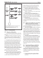
2.C Locating Vent & Combustion Air
Terminals
2.C.1 Side Wall Vent Terminal
The appropriate Laars side wall vent terminal
must be used, and is listed in the installation and
operation manual. The terminal provides a means of
installing the vent piping through the building wall,
and must be located in accordance with ANSI Z223.1/
NFPA 54 and applicable local codes. In Canada, the
installation must be in accordance with CSA B149.1
and local applicable codes. Consider the following
when installing the terminal:
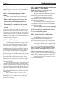
1. Figure 4 shows the requirements for mechanical
vent terminal clearances for the U.S. and Canada.
2. Locate the vent terminal so that vent gases cannot
be drawn into air conditioning system inlets.
3. Locate the vent terminal so that vent gases cannot
enter the building through doors, windows, gravity
inlets or other openings. Whenever possible,
locations under windows or near doors should be
avoided.
4. Locate the vent terminal so that it cannot be
blocked by snow. The installer may determine that
a vent terminal must be higher than the minimum
shown in codes, depending upon local conditions.
5. Locate the terminal so the vent exhaust does not
settle on building surfaces or other nearby objects.

Mighty Therm2 (200, 300, 400)
Page 11
U.S. Installations (see note 1) Canadian Installations (see note 2)
A= Clearance above grade, veranda, porch, 12 inches (30 cm) 12 inches (30 cm)
deck, or balcony
B= Clearance to window or door that may Direct Vent Only: 12 inches (30 cm)
be opened Other Than Direct Vent: 4 feet (1.2 m) below or 36 inches (91 cm)
to side of opening; 1 foot (30 cm) above opening
C= Clearance to permanently closed window See note 4 See note 5
D= Vertical clearance to ventilated sot located
above the terminal within a horizontal See note 4 See note 5
distance of 2 feet (61cm) from the center line of the terminal
E= Clearance to unventilated sot See note 4 See note 5
F= Clearance to outside corner See note 4 See note 5
G= Clearance to inside corner See note 4 See note 5
H= Clearance to each side of center line See note 4 3 feet (91 cm) within a height 15 feet
extended above meter/regulator assembly above the meter/regulator assembly
I= Clearance to service regulator vent outlet See note 4 3 feet (91 cm)
J= Clearance to non mechanical air supply Direct Vent Only: 12 inches (30 cm)
inlet to building or the combustion air inlet Other Than Direct Vent: 4 feet (1.2 m) below or 36 inches (91 cm)
to any other appliance to side of opening; 1 foot (30 cm) above opening
K= Clearance to a mechanical air supply inlet 3 feet (91 cm) above if within 10 feet (3 m) 6 feet (1.83 m)
horizontally
L= Clearance above paved sidewalk or paved Vent termination not allowed in this location Vent termination not allowed in this
driveway located on public property location
M= Clearance under veranda, porch, deck, See note 4 12 inches (30 cm) (see note 3)
or balcony
Notes:
1. In accordance with the current ANSI Z223.1 / NFPA 54 National Fuel Gas Code.
2. In accordance with the current CSA B149.1, Natural Gas and Propane Installation Code.
3. Permitted only if veranda, porch, deck, or balcony is fully open on a minimum of two sides beneath the oor.
4. For clearances not specied in ANSI Z223.1 / NFPA 54, clearance is in accordance with local installation codes and the requirements of
the gas supplier.
5. For clearances not specied in CSA B149.1, clearance is in accordance with local installation codes and the requirements of the gas
supplier.
Figure 4. Vent Terminal Clearance.

LAARS Heating Systems
Page 12
Vent products may damage such surfaces or
objects.
6. If the boiler or water heater uses ducted
combustion air from an intake terminal located on
the same wall, locate the vent terminal at least 3
feet (0.9m) horizontally from the combustion air
terminal, and locate the vent terminal at least 1
foot (0.3m) above the combustion air terminal
WARNING
The outdoor vent terminal gets hot. Unit must
be installed in such a way as to reduce the risk
of burns from contact with the vent terminal.
AVERTISSEMENT
La sortie d’évent à l’extérieur devient très
chaude. Elle doit être installée de façon à
réduire le risque de brûlures au contact de
l’extrémité de l’évent.
Important Note: Massachusetts Code
Requirement.
From Massachusetts Rules and Regulations 248
CMR 5.08:
(a) For all side wall horizontally vented gas fueled
equipment installed in every dwelling, building
or structure used in whole or in part for
residential purposes, including those owned or
operated by the Commonwealth and where the
side wall exhaust vent termination is less than
seven (7) feet above nished grade in the area of
the venting, including but not limited to decks
and porches, the following requirements shall
be satised:
1. INSTALLATION OF CARBON MONOXIDE
DETECTORS.
At the time of installation of the side wall horizontal
vented gas fueled equipment, the installing
plumber or gastter shall observe that a hard-
wired carbon monoxide detector with an alarm
and battery back-up is installed on the oor
level where the gas equipment is to be installed.
In addition, the installing plumber or gastter
shall observe that a battery operated or hard-
wired carbon monoxide detector with an alarm is
installed on each additional level of the dwelling,
building or structure served by the side wall
horizontal vented gas fueled equipment. It shall be
the responsibility of the property owner to secure
the services of qualied licensed professionals for
the installation of hard-wired carbon monoxide
detectors.
a. In the event that the side wall horizontally vented
gas fueled equipment is installed in a crawl space
or an attic, the hard-wired carbon monoxide
detector with alarm and battery back-up may be
installed on the next adjacent oor level.
b. In the event that the requirements of this
subdivision cannot be met at the time of
completion of installation, the owner shall have a
period of thirty (30) days to comply with the above
requirements; provided, however, that during said
thirty (30) day period, a battery operated carbon
monoxide detector with an alarm shall be installed.
2. APPROVED CARBON MONOXIDE
DETECTORS.
Each carbon monoxide detector as required in
accordance with the above provisions shall comply
with NFPA 720 and be ANSI/UL 2034 listed and
IAS certied.
3. SIGNAGE.
A metal or plastic identication plate shall be
permanently mounted to the exterior of the
building at a minimum height of eight (8) feet
above grade directly in line with the exhaust vent
terminal for the horizontally vented gas fueled
heating appliance or equipment. The sign shall
read, in print size no less than one-half (½) inch
in size, “GAS VENT DIRECTLY BELOW. KEEP
CLEAR OF ALL OBSTRUCTIONS”.
4. INSPECTION.
The state or local gas inspector of the side wall
horizontally vented gas fueled equipment shall not
approve the installation unless, upon inspection,
the inspector observes carbon monoxide detectors
and signage installed in accordance with the
provisions of 248 CMR 5.08(2)(a) 1 through 4.
(b) EXEMPTIONS: The following equipment is
exempt from 248 CMR 5.08(2)(a) 1 through 4:
1. The equipment listed in Chapter 10 entitled
“Equipment Not Required To Be Vented” in the
most current edition of NFPA 54 as adopted by the
Board; and
2. Product Approved side wall horizontal vented gas
fueled equipment installed in a room or structure
separate from the dwelling, building or structure
used in whole or in part for residential purposes.
(c) MANUFACTURER REQUIREMENTS –
GAS EQUIPMENT VENTING SYSTEM
PROVIDED. When the manufacturer of
Product Approved side wall horizontally vented
gas equipment provides a venting system
design or venting system components with the
equipment, the instructions provided by the
manufacturer for installation of the equipment
and the venting system shall include:

Mighty Therm2 (200, 300, 400)
Page 13
1. Detailed instructions for the installation of the
venting system design or the venting system
components; and
2. A complete parts list for the venting system design
or venting system.
(d) MANUFACTURER REQUIREMENTS – GAS
EQUIPMENT VENTING SYSTEM NOT
PROVIDED. When the manufacturer of a
Product Approved side wall horizontally vented
gas fueled equipment does not provide the parts
for venting the fuel gases, but identies “special
venting systems”, the following requirements
shall be satised by the manufacturer:
1. The referenced “special venting system”
instructions shall be included with the appliance or
equipment installation instructions; and
2. The “special venting systems” shall be Product
Approved by the Board, and the instructions for
that system shall include a parts list and detailed
installation instructions.
(e) A copy of all installation instructions for all
Product Approved side wall horizontally vented
gas fueled equipment, all venting instructions,
all parts lists for venting instructions, and/or all
venting design instructions shall remain with
the appliance or equipment at the completion of
the installation.
2.C.2 Side Wall
Combustion Air Terminal
The Laars side wall combustion air terminal (listed
in Table 1) must be used when the unit takes
its combustion air through a duct from a side
wall. Consider the following when installing the
terminal:
1. Do not locate the air inlet terminal near a source
of corrosive chemical fumes (e.g., cleaning uid,
chlorinated compounds, etc.)
2. Locate the terminal so that it will not be subject to
damage by accident or vandalism.
3. Locate the combustion air terminal so that it
cannot be blocked by snow. The National Fuel Gas
Code requires that it be at least 12 inches (30 cm)
above grade, but the installer may determine it
should be higher, depending upon local conditions.
4. If the Mighty Therm2 is side-wall vented to the
same wall, locate the vent terminal at least 3
feet (0.9m) horizontally from the combustion air
terminal, and locate the vent terminal at least 1
foot (0.3m) above the combustion air terminal (see
Figure 4).
2.C.3 Vertical Vent Terminal
When the unit is vented through the roof, the
vent must extend at least 3 feet (0.9m) above the point
at which it penetrates the roof. It must extend at least
2 feet (0.6m) higher than any portion of a building
within a horizontal distance of 10 feet (3.0m), and high
enough above the roof line to prevent blockage from
snow. When the combustion air is taken from the roof,
the combustion air must terminate at least 12" (30cm)
below the vent terminal (see Figure 3).
2.C.4 Vertical Combustion Air Terminal
When combustion air is taken from the roof, a
eld-supplied rain cap or an elbow arrangement must
be used to prevent entry of rain water (see Figure 3).
The opening on the end of the terminal must be at least
12" (30cm) above the point at which it penetrates the
roof, and high enough above the roof line to prevent
blockage from snow. When the vent terminates on the
roof, the combustion air must terminate at least 12"
(30cm) below the vent terminal.
2.D Common Vent Test — Boilers
When an existing boiler is removed from a
common venting system, the common venting system
is likely to be too large for proper venting of the
appliances remaining connected to it.
At the time of removal of an existing boiler, the
following steps shall be followed with each appliance
remaining connected to the common venting system
placed in operation, while the other appliances
remaining connected to the common venting system
are not in operation.
1. Seal any unused openings in the common venting
system.
2. Visually inspect the venting system for proper
size and horizontal pitch and determine there is
non blockage or restriction, leakage, corrosion
and other deciencies which could cause an
unsafe condition.
3. Insofar as it is practical, close all building doors
and windows and all doors between the space in
which the appliances remaining connected to the
common venting system are located and other
spaces of the building. Turn on clothes dryers
and any appliance not connected to the common
venting system. Turn on any exhaust fans, such
as range hoods and bathroom exhausts, so they
will operate at maximum speed. Do not operate a
summer exhaust fan. Close replace dampers.
4. Place in operation the appliance being
inspected. Follow the lighting instructions.
Adjust thermostat so appliance will operate
continuously.
5. Test for spillage at the draft hood relief opening
after 5 minutes of main burner operation. Use
the ame of a match or candle, or smoke from a
cigarette, cigar or pipe.

LAARS Heating Systems
Page 14
6. After it has been determined that each appliance
remaining connected to the common venting
system properly vents when tested as outlined
above, return doors, windows, exhaust fans,
replace dampers and any other gas burning
appliance to their previous conditions of use.
7. Any improper operation of the common venting
system should be corrected so that the installation
conforms with the National Fuel Gas Code,
ANSI Z223.1/NFPA 54 and/or CSA B149.1,
Natural Gas and Propane Installation Codes.
When resizing any portion of the common
venting system, the common venting system
should be resized to approach the minimum size
as determined using the appropriate tables in
Appendix F in the National Fuel Gas Code, ANSI
Z223.1/NFPA 54 and/or CSA B149.1, Natural
Gas and Propane Installation Codes.
2.D Véricationdeséventscommuns—
Chaudières
Lorsqu’une chaudière existante est déconnectée
du réseau d’évents commun, ce réseau d’évents
commun devient probablement trop grand pour
les appareils qui lui restent connectés. Lorsqu’une
chaudière existante est retirée, les étapes suivantes
doivent être accomplies pour chaque appareil qui
reste connecté au réseau d’évents commun utilisé,
alors que les autres appareils qui sont encore
connectés au réseau commun d’évents ne sont pas en
fonctionnement.:
1. Sceller toutes les ouvertures non utilisées du
système d'évacuation.
2. Inspecter de façon visuelle le système
d'évacuation pour déterminer la grosseur et
l'inclinaison horizontale qui conviennent et
s'assurer que le système est exempt d'obstruction,
d'étranglement, de fuite, de corrosion et autres
défaillances qui pourraient présenter des risques.
3. Dans la mesure du possible, fermer toutes les
portes et les fenêtres du bâtiment et toutes les
portes entre l'espace où les appareils toujours
raccordés au système d'évacuation sont installés
et les autres espaces du bâtiment. Mettre en
marche les sécheuses, tous les appareils non
raccordés au système d'évacuation common
et tous les ventilateurs d'extraction comme
les hottes de cuisinière et les ventilateurs des
salles de bain. S'assurer que ces ventilateurs
fonctionnent à la vitesse maximale. Ne pas faire
fonctionner les ventilateurs d'été. Fermer les
registres des cheminées.
4. Mettre l'appareil inspecté en marche. Suivre les
instructions d'allumage. Réegler le thermostat de
façon continue.
5. Faire fonctionner le brûleur principal pendant
5 min ensuite, déterminer si le coupe-tirage
déborde à l'ouverture de décharge. Utiliser la
amme d'une allumette ou d'une chandelle ou la
fumée d'une cigarette, d'un cigare ou d'une pipe.
6. Une fois qu'il a été déterminé, selon la méthode
indiquée ci-dessus, que chaque appareil
raccordé au système d'évacuation est mis à l'air
libre de façon adéquate. Remettre les portes
et les fenêtres, les ventilateurs, les registres de
cheminées et les appareils au gaz à leur position
originale.
7. Tout mauvais fonctionnement du système
d'évacuation commun devrait être corrigé
de façon que l'installation soit conforme au
National Fuel Gas Code, ANSI Z223.1/NFPA
54 et (ou) aux codes d'installation CSA-B149.1.
Si la grosseur d'une section du système devrait
être modié, le système devrait être modié pour
respecter les valeurs minimales des tableaux
pertinents de l'appendice F du National Fuel Gas
Code, ANSI Z223.1/NFPA 54 et (ou) les codes
d'installation CSA-B149.1
2.E Vent Terminals for Outdoor Units
For outdoor applications, the vent and
combustion air openings must be covered with proper
terminals to prevent rain, snow and other objects from
falling into the Mighty Therm2.
Outdoor Vent / Air kit part numbers are shown in
Table 6. These kits contain parts for both combustion
air inlet and exhaust vent connections. An angled sheet
metal assembly with louvers replaces the sheet metal
assembly with the air collar. An adapter, a 12" length
of pipe, and a rain cap are included for the exhaust
vent opening.
If local codes allow, Laars kits are not required
for outdoor units. The installer may use 12" of
appropriately sized galvanized single wall or b-type
vent pipe and a rain cap for the exhaust vent. In
addition, an appropriately sized galvanized 90° elbow,
positioned with the opening facing down, may be used
on the combustion air inlet.
Model (Size) Outdoor Vent and
Air Terminal Kit
200 CA003001
300 CA003002
400 CA003003
Table 5. Vent / Air Kits for Outdoor Units.

Mighty Therm2 (200, 300, 400)
Page 15
Distance from Gas Meter or Last Stage Regulator
Model and
Gas Type 0-100'
0-31 m 100-200' 31-61m 200-300' 61-91m
200 natural 1¼" 3.2 cm 1¼" 3.2 cm 1¼" 3.2 cm
200 propane 1" 2.5 cm 1" 2.5 cm 1¼" 3.2 cm
300 natural 1¼" 3.2 cm 1½" 4.0 cm 1½" 4.0 cm
300 propane 1 2.5 cm 1¼" 3.2 cm 1¼" 3.2 cm
400 natural 1¼" 3.2 cm 1½" 4.0 cm 2" 5.0 cm
400 propane 1¼" 3.2 cm 1¼" 3.2 cm 1½" 4.0 cm
Notes:
1. These gures are based on 1/2" (0.12 kPa) water column pressure drop.
2. Check supply pressure and local code requirements before proceeding with work.
3. Pipe ttings must be considered when determining gas pipe sizing.
Table 6. Gas Piping Size.
SECTION 3 Gas Supply and Piping
3.A Gas Supply and Piping
Gas piping should be supported by suitable
hangers or oor stands, not by the appliance.
The Mighty Therm2’s gas train allows the user to
pipe the gas from either the right side or the left side
of the unit. As shipped, the right side of the gas train is
capped o, and there is a manual valve on the left side.
If desired, the manual valve on the left side of the gas
train may be moved to the right side, and the cap on
the right side may be moved to the left.
Review the following instructions before
proceeding with the installation.
1. Verify that the appliance is tted for the proper
type of gas by checking the rating plate. Mighty
Therm2 appliances are equipped to operate at
elevations up to 10,000 feet (3050m). Mighty
Therm2 appliances may be adjusted to operate
properly at altitudes above 2500 feet (see Section
6.5.2) and the input will be reduced if the heating
value of the gas supply is below sea level values.
2. The maximum inlet gas pressure must not
exceed 13" w.c. (3.2kPa). The minimum inlet gas
pressure is 5 in. w.c. (1.2 kPa).
3. Refer to Table 6, to size supply.
4. Run gas supply line in accordance with all
applicable codes.
5. Locate and install manual shuto valves in
accordance with state and local requirements.
6. A sediment trap must be provided upstream of
the gas controls.
7. All threaded joints should be coated with
piping compound resistant to action of liqueed
petroleum gas.
8. The appliance and its individual shuto valve
must be disconnected from the gas supply piping
during any pressure testing of that system at test
pressures in excess of 0.5 psig (3.45 kpa).
9. The unit must be isolated from the gas supply
system by closing its individual manual shuto
valve during any pressure testing of the gas
supply piping system at test pressures equal to or
less than 0.5 psig (3.45 kpa).
10. The appliance and its gas connection must be
leak tested before placing it in operation.
11. Purge all air from gas lines.
WARNING
Do not use open flame to check for leaks.
An open flame could lead to explosion, which
could result in property damage, serious injury
or death.
AVERTISSEMENT
Ne recherchez pas les fuites avec une flamme
nue. Une flamme nue peut provoquer une
explosion qui peut causer des dommages
matériels, de sérieuses blessures corporelles
ou la mort.
NOTE: The Mighty Therm2 appliance and all other
gas appliances sharing the gas supply line must
be firing at maximum capacity to properly measure
the inlet supply pressure. The pressure can be
measured at the supply pressure port on the gas
valve. Low gas pressure could be an indication of
an undersized gas meter, undersized gas supply
lines and/or an obstructed gas supply line.

LAARS Heating Systems
Page 16
SECTION 4 Water Connections —
4.A Mighty Therm2 Boiler
4.A.1 Heating System Piping:
Hot Supply Connections — Boiler
NOTE: This appliance must be installed in a closed
pressure system with a minimum of 12 psig (82.7
kPa) static pressure at the boiler.
Hot water piping should be supported by suitable
hangers or oor stands. Do not support piping with
this appliance. Due to expansion and contraction of
copper pipe, consideration should be given to the type
of hangers used. Rigid hangers may transmit noise
through the system resulting from the piping sliding in
the hangers. It is recommended that padding be used
when rigid hangers are installed. Maintain 1" clearance
to combustibles for hot water pipes.
Pipe the discharge of the relief valve (full size)
to a drain or in a manner to prevent injury in the event
of pressure relief. Install an air purger, an air vent,
a diaphragm-type expansion tank, and a hydronic
ow check in the system supply loop. Minimum ll
pressure must be 12 psig (82.7 kPa). Install shuto
valves where required by code.
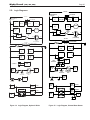
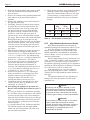
Suggested piping diagrams are shown as Figure 5,
Figure 6, Figure 7, and Figure 8, and Figure 9. These
diagrams are meant only as a guide. Components
required by local codes must be properly installed.
4.A.2 Cold Water Make-Up — Boiler
1. Connect the cold water supply to the inlet
connection of an automatic ll valve.
2. Install a suitable back ow preventer between the
automatic ll valve and the cold water supply.
3. Install shut o valves where required.
NOTE: The boiler, when used in connection with a
refrigeration system, must be installed so the chilled
medium is piped in parallel with the boiler with
appropriate valves to prevent the chilled medium
from entering the boiler.
The boiler piping system of a hot water heating
boiler connected to heating coils located in air
handling appliances where they may be exposed to
refrigerated air circulation must be equipped with ow
control valves or other automatic means to prevent
gravity circulation of the boiler water during the
cooling cycle.
A boiler installed above radiation level, or as
required by the authority having jurisdiction, must be
provided with a low water cuto device either as a part
of the boiler or at the time of boiler installation.
4.A.3 Water Flow Requirements — Boiler
A hydronic heating (closed loop) application
recirculates the same uid in the piping system. As a
result, no new minerals or oxygen are introduced into
the system. To ensure a proper operating temperature
leading to long boiler life, a ow rate has been
established based on the uid temperature rise for this
specic size boiler.
Pump-mounted boilers can be ordered for use in
primary secondary piping systems. The pumps used
are sized for the head loss through the heater, plus 30
feet (9.1 m) of full-sized piping (same size as boiler
outlet) and a normal number of ttings.
Table 8 species water ow rates for boilers,
which will enable the user to size a pump. The head
loss shown is for the heater only, and the user will
need to add the head loss of the system piping to
properly size the pump.
The minimum inlet water temperature for the
Mighty Therm2 is 120°F (49°C) to avoid condensing
on the copper coils.
4.A.4 Freeze Protection — Boiler
Boiler installations are not recommended in
areas where the danger of freezing exists unless proper
precautions are made for freeze protection. A non
toxic, heating system, anti-freeze may be added to
the hydronic system provided that the concentration
does not exceed 50% and the anti freeze contains an
anti foamant. When a 50/50 mixture is used, increase
the water ow requirements by 15%, and increase the
head loss requirements by 20%.
Power outage, interruption of gas supply, failure
of system components, activation of safety devices,
etc., may prevent a boiler from ring. Any time a
boiler is subjected to freezing conditions, and the
boiler is not able to re, and/or the water is not able
to circulate, there is a risk of freezing in the boiler
or in the pipes in the system. When water freezes,
it expands. This can result in bursting of pipes in the
system, or damage to the boiler, which could result in
leaking or ooding conditions.
IMPORTANT NOTES: Different glycol products
may provide varying degrees of protection. Glycol
products must be maintained properly in a heating
system, or they may become ineffective. Consult
the glycol specifications, or the glycol manufacturer,
for information about specific products,
maintenance of solutions, and set up according to
your particular conditions. Never use ethylene glycol
(automotive antifreeze).

Mighty Therm2 (200, 300, 400)
Page 17
Model
(Size)
20°F 25°F 30°F 35°F
flow
gpm
H/L
feet
flow
gpm
H/L
feet
flow
gpm
H/L
feet
flow
gpm
H/L
feet
200 17 1.6 14 1.0 11 0.7 10 0.5
300 26 3.5 20 2.3 17 1.6 15 1.2
400 34 6.3 27 4.0 23 2.8 19 2.1
Metric Equivalent
Model
(Size)
11°C 14°C 17°C 19°C
ow
lpm
H/L
m
ow
lpm
H/L
m
ow
lpm
H/L
m
ow
lpm
H/L
m
200 64 0.5 51 0.3 43 0.2 37 0.2
300 97 1.1 77 0.7 64 0.5 55 0.4
400 129 1.9 103 1.2 86 0.9 74 0.6
Notes: gpm = gallons per minute, lpm = liters per minute,
H/L = head loss, ft = head loss in feet,
m = head loss in meters.
Maximum temperature rise is 35°F (19°C), as shown.
Head loss is for boiler’s heat exchanger only.
N/R = not recommended.
Table 7. Water Flow Requirements - MT2H.
Figure 5. Hydronic Piping — Multiple Boilers, Primary Secondary System.
4.B Water Connections —
Mighty Therm2 Water Heater
4.B.1 Water System Piping — Water Heater
Hot water piping should be supported by suitable
hangers or oor stands. Do not support piping with
this appliance. Due to expansion and contraction of
copper pipe, consideration should be given to the type
of hangers used. Rigid hangers may transmit noise
through the system resulting from the piping sliding in
the hangers. It is recommended that padding be used
when rigid hangers are installed.
The Mighty Therm2 can be used with several
dierent types of readily available storage tanks. A
pump draws water from the storage tank and pumps
the water through the heater and back into the tank.
Pump-mounted units have a circulating pump built
into the water heater. The pumps used are sized for
the head loss through the heater, plus 30 feet (9.1 m)
of full-sized piping (same size as boiler outlet) and
a normal number of ttings. Pumps used on pump-
mounted unit are sized for soft/normal or hard water,
so make sure a pump-mounted unit matches the water
quality of the installation.
Pipe the outlet from the heater’s relief valve
such that any discharge from the relief valve will be
conducted to a suitable place for disposal when relief
occurs. Do not reduce line size or install any valves in
this line. The line must be installed to allow complete
drainage of both the valve and the line.
Suggested piping diagrams are shown as Figure 5,
Figure 6, Figure 7, and Figure 8, and Figure 9. These
diagrams are meant only as a guide. Components
required by local codes must be properly installed.

LAARS Heating Systems
Page 18
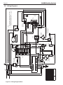
Figure 6. Hydronic Piping — Multiple Boilers, Low Temperature System.
Figure 7. Hydronic Piping — One Boiler, Multi-Temperature System.

Mighty Therm2 (200, 300, 400)
Page 19
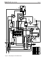
Figure 8. Hydronic Piping — Primary-Secondary, Reverse-Return.
Figure 9. Hydronic Piping — Primary-Secondary, Reverse-Return, Low Temperature.

LAARS Heating Systems
Page 20
The minimum inlet water temperature for the
Mighty Therm2 is 130°F (54°C) to avoid condensing
on the copper coils.
4.B.2 Hot Water Supply Piping —Water
Heater
Follow the tank manufacturer’s guidelines for
completion of the hot water system connections.
NOTE: A listed temperature and pressure relief
valve listed as complying with the Standard
for Relief Valves and Automatic Gas Shutoff
Devices for Hot Water Supply Systems (ANSI
Z21.22/CSA 4.4), of suitable discharge capacity
must be installed in the separate storage tank
system.
If the Mighty Therm2 water heater is installed
in a closed water supply system, such as one having a
backow preventer in the cold water supply line, the
relief valve may discharge periodically, due to thermal
expansion. Means (such as a properly-sized expansion
tank) shall be provided to control thermal expansion.
Contact the water supplier or local plumbing inspector
on how to control this situation.
4.B.3 Water Flow Requirements —
Water Heater
In a water heating application (an open system),
new water is constantly being introduced. With the
new water comes a fresh supply of minerals that can
be deposited on the unit’s heat exchanger. This is
commonly known as scaling. The amount of minerals
will depend upon the hardness of the water. Water can
also be aggressive, and can erode metals, including
copper, if the water is moved too quickly. The water
ow requirements for the Mighty Therm2 water heater
are based upon the hardness of the water. The water
ow is kept high enough to prevent scaling, but low
enough to prevent tube erosion. For extremely soft or
hard water, cupro-nickel tubes are available. Contact a
Laars representative if you have questions or concerns
about water quality.
Pump-mounted water heaters can be ordered with
standard pumps for soft or normal water. The pumps
used are sized for the head loss through the heater, plus
30 feet (9.1m) of full-sized piping (same size as heater
outlet) and a normal number of ttings. For hard water
conditions (more than 17 grains per gallon), use a
non-pump-mounted heater with a properly-sized eld-
installed pump.
Table 9 species water ow rates for water
heaters, which will enable the user to size a pump. The
head loss shown is for the heater only, and the user
will need to add the head loss of the piping system to
properly size the pump.
4.B.4 Combined Water Heating (potable) and
Space Heating — Water Heater
NOTE: These systems are not allowed in the
Commonwealth of Massachusetts.
Piping and components connected to this water
heater for the space heating application shall be
suitable for use with potable water.
Toxic chemicals, such as used for boiler
treatment, shall not be introduced into the potable
water used for space heating.
This water heater when used to supply potable
water shall not be connected to any heating system
or component(s) previously used with a non-potable
water heating appliance.
When the system requires water for heating at
temperatures higher than required for other uses,
an anti-scald mixing or tempering valve shall be
installed to temper the water for those uses in order
to reduce scald hazard potential.
4.B.5 Freeze Protection — Water Heater
Although Mighty Therm2 water heaters are
design-certied for outdoor installations, such
installations are not recommended in areas subject to
freezing temperatures, unless proper precautions are
taken.
Power outage, interruption of gas supply, failure
of system components, activation of safety devices,
etc., may prevent a heater from ring. Any time a
heater is subjected to freezing conditions, and the
heater is not able to re, and/or the water is not
able to circulate, there is a risk of freezing in the
heater or in the pipes in the system. When water
freezes, it expands. This can result in bursting of pipes
in the system, or damage to the heater, which could
result in leaking or ooding conditions.
Contact the local factory representative or Laars
for additional information.
La page est en cours de chargement...
La page est en cours de chargement...
La page est en cours de chargement...
La page est en cours de chargement...
La page est en cours de chargement...
La page est en cours de chargement...
La page est en cours de chargement...
La page est en cours de chargement...
La page est en cours de chargement...
La page est en cours de chargement...
La page est en cours de chargement...
La page est en cours de chargement...
La page est en cours de chargement...
La page est en cours de chargement...
La page est en cours de chargement...
La page est en cours de chargement...
La page est en cours de chargement...
La page est en cours de chargement...
La page est en cours de chargement...
La page est en cours de chargement...
La page est en cours de chargement...
La page est en cours de chargement...
La page est en cours de chargement...
La page est en cours de chargement...
-
 1
1
-
 2
2
-
 3
3
-
 4
4
-
 5
5
-
 6
6
-
 7
7
-
 8
8
-
 9
9
-
 10
10
-
 11
11
-
 12
12
-
 13
13
-
 14
14
-
 15
15
-
 16
16
-
 17
17
-
 18
18
-
 19
19
-
 20
20
-
 21
21
-
 22
22
-
 23
23
-
 24
24
-
 25
25
-
 26
26
-
 27
27
-
 28
28
-
 29
29
-
 30
30
-
 31
31
-
 32
32
-
 33
33
-
 34
34
-
 35
35
-
 36
36
-
 37
37
-
 38
38
-
 39
39
-
 40
40
-
 41
41
-
 42
42
-
 43
43
-
 44
44


Laars MT2H0300NACK2BXN Guide d'installation
- Taper
- Guide d'installation
- Ce manuel convient également à
dans d''autres langues
Documents connexes
-
Laars MT2V1000NACK1PXN Mode d'emploi
-
-
Laars Mini-Therm JX Residential Gas-Fired Hydronic Boilers Manuel utilisateur
-
-
-
-
Laars JVS160P Guide d'installation
-
Autres documents
-
HeatStar 8944969 Le manuel du propriétaire
-
 Mighty Max Cart PO600C-GN-YL Mode d'emploi
-
Enviro EnviroSense 6G50 76N Manuel utilisateur
-
Dunkirk DWB Series Installation, Operation & Maintenance Manual
-
Modine Separated Combustion Gas-Fired Unit Heaters Heaters Installation & Service Manual
-
-
Comfort Glow DVN11/DVP11/DVN17/DVP17/DVN25/DVP25 Le manuel du propriétaire
-
Bradford White Brute Mini Manuel utilisateur
-
-
