Comtrend Corporation PG-9182A Manuel utilisateur
- Catégorie
- Les routeurs
- Taper
- Manuel utilisateur

Version A1.0, Jan. 29, 2018
PG-9182AC
Powerline Ethernet WiFi Adapter
User Manual of web UI Management

1
COPYRIGHT
Copyright ©2013/2014 by this company. All rights reserved. No part of this
Publication may be reproduced, transmitted, transcribed, stored in a retrieval system,
or translated into any language or computer language, in any form or by any means,
electronic, mechanical, magnetic, optical, chemical, manual or otherwise, without the
prior written permission of this company
This company makes no representations or warranties, either expressed or implied,
with respect to the contents hereof and specifically disclaims any warranties,
merchantability or fitness for any particular purpose. Any software described in this
manual is sold or licensed "as is". Should the programs prove defective following their
purchase, the buyer (and not this company, its distributor, or its dealer) assumes the
entire cost of all necessary servicing, repair, and any incidental or consequential
damages resulting from any defect in the software. Further, this company reserves
the right to revise this publication and to make changes from time to time in the
contents thereof without obligation to notify any person of such revision or changes.
Preface
This manual provides information related to the installation and operation of this
device. The individual reading this manual is presumed to have a basic
understanding of telecommunications terminology and concepts.
If you find the product to be inoperable or malfunctioning, please contact technical
support for immediate service by email at INT-support@comtrend.com
For product update, new product release, manual revision, or software upgrades,
please visit our website at http://www.comtrend.com

2
Copyright
Copyright©2017 Comtrend Corporation. All rights reserved. The information
contained herein is proprietary to Comtrend Corporation. No part of this document
may be translated, transcribed, reproduced, in any form, or by any means without
prior written consent of Comtrend Corporation.
This program is free software: you can redistribute it and/or modify it under the terms
of the GNU General Public License as published by the Free Software Foundation,
either version 3 of the License, or (at your option) any later version.
This program is distributed in the hope that it will be useful, but WITHOUT ANY
WARRANTY; without even the implied warranty of MERCHANTABILITY or FITNESS
FOR A PARTICULAR PURPOSE. See the GNU General Public License for more details.
You should have received a copy of the GNU General Public License along with this
program. If not, see http://www.gnu.org/licenses/
NOTE: This document is subject to change without notice.
Protect Our Environment
This symbol indicates that when the equipment has reached the end of its
useful life, it must be taken to a recycling centre and processed separate
from domestic waste.
The cardboard box, the plastic contained in the packaging, and the parts
that make up this PLC can be recycled in accordance with regionally
established regulations. Never dispose of this electronic equipment along
with your household waste; you may be subject to penalties or sanctions
under the law. Instead, please be responsible and ask for disposal
instructions from your local government.
Save Our Environment
When this equipment has reached the end of its useful life, it must be taken to a
recycling centre and processed separately from domestic waste.
The cardboard box, the plastic in the packaging, and the parts that make up this
device can be recycled in accordance with regionally established regulations. Never
dispose of this electronic equipment along with your household waste.
You may be subject to penalties or sanctions under the law. Instead, ask for disposal
instructions from your municipal government.
Please be responsible and protect our environment.

3
CATALOG
CHAPTER 1: GENERAL INFORMATION .......................................................................................... 4
1-1 SAFETY INFORMATION ..................................................................................................................... 4
1-2 SYSTEM REQUIREMENTS .................................................................................................................. 7
CHAPTER 2: SYSTEM AND NETWORK SETUP .............................................................................. 8
2-1 CONNECTING TO POWER LINE ACCESS POINT BY WEB BROWSER.................................................... 8
2-2 CONNECTING TO WEB MANAGEMENT INTERFACE ......................................................................... 9
2-3 VIEW SYSTEM INFORMATION ......................................................................................................... 10
2-3 NETWORK SETTINGS ...................................................................................................................... 12
2-4 STATION LIST .................................................................................................................................. 12
2-5 TIME SETTINGS ............................................................................................................................... 13
2-6 ACCESS POLICY .............................................................................................................................. 13
2-7 ADMINISTRATION ............................................................................................................................ 14
2-8 MONITOR ........................................................................................................................................ 15
2-9 LOGOUT .......................................................................................................................................... 15
CHAPTER 3: WIRELESS CONFIGURATIONS ................................................................................... 16
3-1 2.4G WIRELESS SETTINGS ............................................................................................................. 16
3-2 2.4G SECURITY SETTINGS .............................................................................................................. 17
3-3 2.4G WPS SETTINGS ...................................................................................................................... 18
3-4 5G WIRELESS SETTINGS ................................................................................................................ 18
3-5 5 G SECURITY SETTINGS ................................................................................................................ 19
3-6 5G WPS SETTINGS ......................................................................................................................... 20
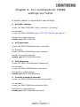
CHAPTER 4: CLI COMMANDS FOR TR069 SETTINGS VIA TELNET ........................................... 21
nvram_get 2860 TR069InformInterval .............................................................................................. 21
The setup images used in this manual are for reference only.
The contents of these images may vary according to firmware
version. The official image contents are based on the newest
firmware version.

4
Chapter 1: General Information
1-1 Safety Information
In order to keep the safety of users and your properties, please follow the
following safety instructions:
1. This power line access point is designed for indoor use only; DO NOT place
this power line access point outdoor.
2. DO NOT put this power line access point at or near hot or humid places, like
kitchen or bathroom. Also, do not leave this power line access point in the car
under direct sunlight.
3. DO NOT pull any connected cable with force; disconnect it from the power line
access point first.
4. If you want to place this power line access point at high places or hang on the
wall, please make sure the power line access point is firmly secured. Falling from
high places would damage the power line access point and its accessories, and
warranty will be void.
5. There’s no user-serviceable part inside the access point. If you found that the
power line access point is not working properly, please contact your dealer of
purchase and ask for help. DO NOT disassemble the access point, warranty will
be void.
6. If the power line access point falls into water when it’s powered, DO NOT use
your hand to pick it up. Switch the electrical power off before you do anything, or
contact an experienced electrical technician for help.
WARNING
• Disconnect the PLC from the power source before servicing
• For indoor user only
• Do NOT open the casing
• Do NOT use near water
• Do NOT insert sharp objects into the adapter’s socket
• Socket maximum output is 15A
Power Specifications:
I/P: 100-240Vac, 50/60Hz, 15A
O/P:100-240Vac, 50/60Hz, 15A

5
Federal Communications Commission (FCC) Statement
15.21
You are cautioned that changes or modifications not expressly approved by the part responsible
for compliance could void the user’s authority to operate the equipment.
15.105(b)
This equipment has been tested and found to comply with the limits for a Class B digital device,
pursuant to part 15 of the FCC rules. These limits are designed to provide reasonable protection
against harmful interference in a residential installation.
This equipment generates uses and can radiate radio frequency energy and, if not installed and
used in accordance with the instructions, may cause harmful interference to radio
communications. However, there is no guarantee that interference will not occur in a particular
installation. If this equipment does cause harmful interference to radio or television reception,
which can be determined by turning the equipment off and on, the user is encouraged to try to
correct the interference by one or more of the following measures:
-Reorient or relocate the receiving antenna.
-Increase the separation between the equipment and receiver.
-Connect the equipment into an outlet on a circuit different from that to which the receiver is
connected.
-Consult the dealer or an experienced radio/TV technician for help.
This device complies with part 15 of the FCC Rules. Operation is subject to the following two
conditions:
1) this device may not cause interference and
2) this device must accept any interference, including interference that may cause undesired
operation of the device.
FCC RF Radiation Exposure Statement:
1. This Transmitter must not be co-located or operating in conjunction with any other
antenna or transmitter.
2. This equipment complies with RF radiation exposure limits set forth for an
uncontrolled environment. This equipment should be installed and operated with a
minimum distance of 20 cm between the radiator and your body.

6
ISED
Canadian Notice
This device contains licence-exempt transmitter(s)/receiver(s) that comply with Innovation,
Science and Economic Development Canada’s licence-exempt RSS(s). Operation is subject to
the following two conditions:
1. This device may not cause interference.
2. This device must accept any interference, including interference that may cause
undesired operation of the device.
Avis Canadien
L’émetteur/récepteur exempt de licence contenu dans le présent appareil est conforme aux CNR
d’Innovation, Sciences et Développement économique Canada applicables aux appareils radio
exempts de licence. L’exploitation est autorisée aux deux conditions suivantes :
1. L’appareil ne doit pas produire de brouillage;
2. L’appareil doit accepter tout brouillage radioélectrique subi, même si le brouillage est
susceptible d’en compromettre le fonctionnement.
Caution: Exposure to Radio Frequency Radiation.
1. To comply with the Canadian RF exposure compliance requirements, this device
and its antenna must not be co-located or operating in conjunction with any other
antenna or transmitter.
2. To comply with RSS 102 RF exposure compliance requirements, a separation
distance of at least 20 cm must be maintained between the antenna of this device
and all persons.
Attention: exposition au rayonnement radiofréquence.
1. Pour se conformer aux exigences de conformité RF canadienne l'exposition, cet
appareil et son antenne ne doivent pas être co-localisés ou fonctionnant en
conjonction avec une autre antenne ou transmetteur.
2. Pour se conformer aux exigences de conformité CNR 102 RF exposition, une
distance de séparation d'au moins 20 cm doit être maintenue entre l'antenne de
cet appareil et toutes les personnes.
Operation in the band 5150-5250 MHz is only for indoor use to reduce the
potential for harmful interference to co-channel mobile satellite systems.
La bande 5 150-5 250 MHz est réservés uniquement pour une utilisation à l'intérieur afin de réduire
les risques de brouillage préjudiciable aux systèmes de satellites mobiles utilisant les mêmes canaux.
For the frequency 5600-5650 MHz, no operation is permitted
Pour la fréquence 5600-5650 MHz, aucune opération est autorisée.

7
1-2 System Requirements
Computer or network devices with wired or wireless network
interface card.
Any connected devices must feature a network port.
Web browser (Microsoft Internet Explorer 4.0 or above, Google
Chrome web browser, Opera web browser, or Safari web
browser).

8
Chapter 2: System and Network Setup
2-1 Connecting to power line access point by
web browser
PG-9082 supports two kinds of management IP simultaneously.
(1) DHCP client, which gets dynamic IP address from
Modem/Broadband Router/Home Gateway.
(2) Static IP, 192.168.0.10 by default, which can be configurable in
web UI.
Before you can connect to the power line access point and start
configuration procedures, your computer must be able to get an IP
address automatically (dynamic IP address). PG-9082 gets dynamic IP
address from Modem/Broadband Router/Home Gateway that it is
connected to by default. However, the current IP info of PG-9082 would
be displayed at Modem/Broadcom Router/Home Gateway.
On other side, Static IP of PG-9082 can be accessed The default static
IP address of PG-9082 is 192.168.0.10, subnet mask 255.255.255.0.
Please use static IP address 291.68.0.100, subnet mask
255.255.255.0 for accessing web UI management.

9
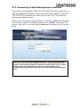
2-2 Connecting to Web Management Interface
All functions and settings of WiFi AP of PG-9082 must be configured via
web management interface. Please start your web browser, and input
‘192.168.0.10’in address bar, then press ‘Enter’ key. The following
message should be shown:
Please input user name and password in the field respectively, default
user name is ‘root’, and default password is ‘12345’, then press ‘OK’
button, and you can see the web management interface of this access
point:
NOTE: If you can’t see the web management interface, and you’re being prompted
to input user name and password again, it means you didn’t input username and
password correctly. Please retype user name and password again. If you’re certain
about the user name and password you type are correct, please go to ‘4-2
Troubleshooting, to perform a factory reset or to set the password back to default
value.

10
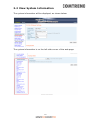
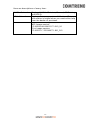
2-3 View System Information
The system information will be displayed, as shown below:
The system information is on the left-side corner of the web page.

11
Here are descriptions of every item:
2.4GHz Network
Displays 2.4GHz AP status, Channel, SSID string
and BSSID.
5GHz Network
Displays Firmware version of Wireless. This
information is helpful when you need online help
from the dealer of purchase.
Common
WiFi and G.hn Image version information.
WiFi Image version:
PG-9082-WLAN-684151CTL-B01_R0
G.hn Image version:
PG-9082-PLC-76R5488CTL-B01_R01

12
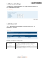
2-3 Network Settings
The static IP for local management. Click “Apply” will reboot system for
new modifications activation.
2-4 Station List
This is page shows the information of wireless Stations that are
connected to PG-9082.
Here are descriptions of every item:
MAC address
This option will disable your Wireless station
connecting to PG-9082 at 2.4G or 5GHz
Interface.
Rate (MCS)
MCS# on wireless interface with the station.
Bandwidth
Bandwidth, 20/40MHz for 2.4GHz,
20/40/80MHz for 5GHz

13
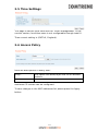
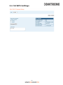
2-5 Time Settings
This page is set the local time zone for TR069 management, in the
current version, local time zone is not configurable through web UI.
Thee current setting is (GMT+0, England).
2-6 Access Policy
Here are descriptions of every item:
Policy:
This option will allow/reject the list of wireless
stations.
Add a station MAC
MAC format is XX:XX:XX:XX:XX:XX
maximum 32 entries can be configured.
To save changes in the MAC addresses list please press the Apply
button

14
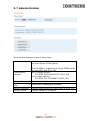
2-7 Administration
Here are descriptions of every setup item:
Software Upgrade
Select the firmware file of WiFi AP of PG-9082 at
the local driver of the laptop.
The PG-9082 is supporting a single TR069 entity
for both WiFi and G.hn PLC
Components
Versions
Wi-Fi Image version:
PG-9082-WLAN-684151CTL-B01_R01
G.hn Image version:
PG-9082-PLC-76R5488CTL-B01_R01
Change Password
Only for “admin” account.
Download Log
Files
Reserved for debugging purpose.
Restore Defaults
Factory reset of the PG-9082 (WiFi & G.hn PLC)
System Reset
System reboot by software.

15
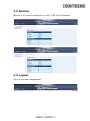
2-8 Monitor
Monitor is to show the statistics on LAN, 2.4G & 5G interfaces.
2-9 Logout
.
Log out the web management.

16
Chapter 3: Wireless Configurations
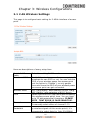
3-1 2.4G Wireless Settings
This page is to configure basic setting for 2.4GHz interface of access
point.
Here are descriptions of every setup item:
Enable 2.4Ghz
Radio
Ticked is enabling 2.4GHz radio.
Broadcast SSID
Decide if the wireless power line access point will
broadcast its own SSID or not. You can hide the
SSID of your wireless power line access point
(set the option to ‘Disable’), so only people
those who know the SSID of your wireless power
line access point can get connected.
Wireless Mode
802.11b/g legacy: auto selection of 802.11b/g.
902.11b/g/n: auto selection of 802.11b/g/n
SSID
Please input the SSID (the name used to identify
this wireless access point) here. You can input
up to 32 alphanumerical characters. PLEASE
NOTE THAT ESSID IS CASE SENSITIVE.
Channel
Auto, in channel1, 6, 11
Or manually select either of channel 1-13.
Channel
Bandwidth
Select wireless channel width (bandwidth taken
by wireless signals of this access point). It’s
suggested to select Auto for ‘Auto 20/40MHz’

17
& ’20 MHz’ only.
VWM
WMM (Wi-Fi Multimedia) technology, which can
improve the performance of certain network
applications, like audio/video streaming,
network telephony (VoIP), and others. When
you enable WMM function, the power line access
point will define the priority of different kinds of
data, to give higher priority to applications
which require instant responding. Therefore you
can improve the performance of such network
applications.
Multiple BSS
Two more SSID are required.
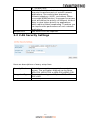
3-2 2.4G Security Settings
Here are descriptions of every setup item:
Security Mode
Select the encryption supported over wireless
access. The encryption method can be None,
WPA-PSK, WPA2-PSK or WPA-PSK+WPA2-PSK.
Encryption Type
There are three types of Cipher :TKIP, AES,
TKIP+AES
Passphase
8 to 63 alphanumerical characters

18
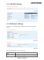
3-3 2.4G WPS Settings
3-4 5G Wireless Settings
This page is to configure basic setting for 5GHz interface of access
point.
Here are descriptions of every setup item:
Enable 5Ghz
Radio
Ticked is enabling 5GHz radio.
Broadcast SSID
Decide if the wireless power line access point will
broadcast its own SSID or not. You can hide the

19
SSID of your wireless power line access point
(set the option to ‘Disable’), so only people
those who know the SSID of your wireless power
line access point can get connected.
SSID
Please input the SSID (the name used to identify
this wireless access point) here. You can input
up to 32 alphanumerical characters. PLEASE
NOTE THAT ESSID IS CASE SENSITIVE.
Country Region
9 for Euprope
Channel
Auto, Or manually select either of channel
Channel
Bandwidth
Select wireless channel width (bandwidth taken
by wireless signals of this access point). It’s
suggested to select for ‘20MHz’, 40MHz, and
‘Auto’ (20/40/80MHz).
VWM
WMM (Wi-Fi Multimedia) technology, which can
improve the performance of certain network
applications, like audio/video streaming,
network telephony (VoIP), and others. When
you enable WMM function, the power line access
point will define the priority of different kinds of
data, to give higher priority to applications
which require instant responding. Therefore you
can improve the performance of such network
applications.
Multiple BSS
Two more SSID are required.
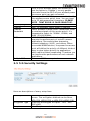
3-5 5 G Security Settings
Here are descriptions of every setup item:
Security Mode
Select the encryption supported over wireless
access. The encryption method can be None,
WPA-PSK, WPA2-PSK or WPA-PSK+WPA2-PSK.
Encryption Type
There are three types of Cipher :TKIP, AES,
TKIP+AES
Passphase
8 to 63 alphanumerical characters
La page est en cours de chargement...
La page est en cours de chargement...
-
 1
1
-
 2
2
-
 3
3
-
 4
4
-
 5
5
-
 6
6
-
 7
7
-
 8
8
-
 9
9
-
 10
10
-
 11
11
-
 12
12
-
 13
13
-
 14
14
-
 15
15
-
 16
16
-
 17
17
-
 18
18
-
 19
19
-
 20
20
-
 21
21
-
 22
22


Comtrend Corporation PG-9182A Manuel utilisateur
- Catégorie
- Les routeurs
- Taper
- Manuel utilisateur
dans d''autres langues
Documents connexes
Autres documents
-
 GL iNet GL-AXT1800 Mode d'emploi
-
Triax TECW 211 Manuel utilisateur
-
 Sunmi P2 Multifunction Base Smart Payment Terminal Mode d'emploi
-
Comtrend PG-9182AC Mode d'emploi
-
Extron WAP 100AC Manuel utilisateur
-
-
-
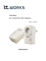 IT Works 500MBPS X2 WIFI/2XRJ45 Le manuel du propriétaire
-
Trendnet TEW-670AP Le manuel du propriétaire
-
Netgear MBR1210 Le manuel du propriétaire


