Comtrend Corporation WAP-5903 Manuel utilisateur
- Catégorie
- Points d'accès WLAN
- Taper
- Manuel utilisateur

USER MANUAL
WAP-5903
WiFi 5 Mesh-Enhanced Extender
Version A1.0, May 21, 2020
261072-045

1
Preface
This manual provides information related to the installation and operation of this
device. The individual reading this manual is presumed to have a basic
understanding of telecommunications terminology and concepts.
If you find the product to be inoperable or malfunctioning, please contact technical
support for immediate service by email at INT-[email protected]
For product update, new product release, manual revision, or software upgrades,
please visit our website at http://www.comtrend.com
EU Liaison Office :
COMTREND CORPORATION / Fijenhof 2, 5662AE Eindhoven, The Netherlands
Comtrend Central Europe, s.r.o. / nkovcova 1518/2, 170 00 Praha 7
Important Safety Instructions
With reference to unpacking, installation, use, and maintenance of your electronic
device, the following basic guidelines are recommended:
• Do not use or install this product near water, to avoid fire or shock hazard. For
example, near a bathtub, kitchen sink or laundry tub, or near a swimming pool.
Also, do not expose the equipment to rain or damp areas (e.g. a wet
basement).
• To safeguard the equipment against overheating, make sure that all openings in
the unit that offer exposure to air are not blocked.
• Avoid using a telephone (other than a cordless type) during an electrical storm.
There may be a remote risk of electric shock from lightening. Also, do not use
the telephone to report a gas leak in the vicinity of the leak.
CAUTION:
n Changes or modifications to this unit not expressly approved by the party
responsible for compliance could void the user authority to operate the
equipment.
n Do not stack equipment or place equipment in tight spaces, in drawers, or
on carpets. Be sure that your equipment is surrounded by at least 2
inches of air space.
n If you experience trouble with this equipment, disconnect it from the
network until the problem has been corrected or until you are sure that
equipment is not malfunctioning.
WARNING
• Disconnect the PLC from the power source before servicing
• For indoor user only
• Do NOT open the casing
• Do NOT use near water
• Do NOT insert sharp objects into the adapter’s socket
n Power Specifications:
I/P: 100-240Vac, 50/60Hz, 0.6A

2
User Information
Any changes or modifications not expressly approved by the party responsible for
compliance could void your authority to operate the equipment.
Aucune modification apportée à l’appareil par l’utilisateur, q u e l l e q u ’ e n s o i t l a
nature. Tout changement ou modification peuvent annuler le droit d’utilisation de
l’appareil par l’utilisateur.
Note: This equipment has been tested and found to comply with the limits for a
Class B digital device, pursuant to part 15 of the FCC Rules. These limits are
designed to provide reasonable protection against harmful interference in a
residential installation. This equipment generates, uses and can radiate radio
frequency energy and, if not installed and used in accordance with the instructions,
may cause harmful interference to radio communications. However, there is no
guarantee that interference will not occur in a particular installation. If this
equipment does cause harmful interference to radio or television reception, which
can be determined by turning the equipment off and on, the user is encouraged to
try to correct the interference by one or more of the following measures:
—Reorient or relocate the receiving antenna.
—Increase the separation between the equipment and receiver.
—Connect the equipment into an outlet on a circuit different from that to which the
receiver is connected.
—Consult the dealer or an experienced radio/TV technician for help.
This device complies with Part 15 of the FCC Rules. Operation is subject to the
following two conditions: (1) This device may not cause harmful interference, and
(2) this device must accept any interference received, including interference that
may cause undesired operation.
This Class B digital apparatus complies with Canadian ICES-003.
To reduce potential radio interference t o other users, the antenna type and
its gain should be so chosen that the equivalent isotropically radiated power
(e.i.r.p.) is not more than that permitted for successful communication.
This device complies with Part 15 of the FCC Rules and Industry Canada licence-
exempt RSS standard(s).
Operation is subject to the following two conditions:
1. This device may not cause interference, and
2. This device must accept any interference, including interference that may
cause undesired operation of the device.
Cet appareil numérique de la classe B est conforme à la norme NMB-003 Canada.
Pour réduire le risque d’interférence aux autres utilisateurs, le type d’antenne
et son gain doivent être choisies de façon que la puissance isotrope
rayonnée équivalente (PIRE) ne dépasse pas ce qui est nécessaire pour une
communication réussie.
Cet appareil est conforme à la norme RSS Industrie Canada exempts de licence
norme(s).
Son fonctionnement est soumis aux deux conditions suivantes:
1. Cet appareil ne peut pas provoquer d’interférences et
2. Cet appareil doit accepter toute interférence, y compris les interférences
qui peuvent causer un mauvais fonctionnement du dispositif.
Radiation Exposure
FCC
1. This Transmitter must not be co-located or operating in conjunction with any
other antenna or transmitter.

3
2. This equipment complies with FCC RF radiation exposure limits set forth for an
uncontrolled environment. This equipment should be installed and operated with a
minimum distance of 25 cm between the radiator and your body.
ISED
This device complies with the ISED radiation exposure limit set forth for an
uncontrolled environment. This device should be installed and operated with
minimum distance 25 cm between the radiator & your body. This transmitter must
not be co-located or operating in conjunction with any other antenna or
transmitter.
“This product meets the applicable Innovation, Science and Economic
development Canada technical specifications”.
The device for operation in the band 5150–5250 MHz is only for indoor use to
reduce the potential for harmful interference to co-channel mobile satellite
systems.
This product meets the applicable Industry Canada technical specifications.
The Ringer Equivalence Number (REN) indicates the maximum number of devices
allowed to be connected to a telephone interface. The termination of an interface
may consist of any combination of devices subject only to the requirement that the
sum of the RENs of all the devices not exceed five.
Cet équipement est conforme avec l'exposition aux radiations ISED définies pour
un environnement non contrôlé. Cet équipement doit être installé et utilisé à une
distance minimum de 25 cm entre le radiateur et votre corps. Cet émetteur ne doit
pas être co-localisées ou opérant en conjonction avec une autre antenne ou
transmetteur.
«Ce produit est conforme aux spécifications techniques applicables d'Innovation,
Sciences et Développement économique Canada».
les dispositifs fonctionnant dans la bande 5150-5250 MHz sont réservés
uniquement pour une utilisation à l’intérieur afin de réduire les risques de
brouillage préjudiciable aux systèmes de satellites mobiles utilisant les
mêmes canaux.
Le présent matériel est conforme aux specifications techniques applicables
d’Industrie Canada.
L’indice d’équivalence de la sonnerie (IES) sert à indiquer le nombre maximal de
terminaux qui peuvent être raccordés à une interface téléphonique. La terminaison
d’une interface peut consister en une combinaison quelconque de dispositifs, à la
seule condition que la somme d’indices d’équivalence de la sonnerie de tous les
dispositifs n’excède pas cinq.
Le numéro REN (Ringer Equivalence Number) indique le nombre maximal de
périphériques pouvant être connectés à une interface téléphonique. La terminaison
d'une interface peut consister en une combinaison quelconque d'appareils, à la
condition que la somme des REN de tous les appareils ne dépasse pas cinq.
Certification
● FCC / IC standard
Part 15B / ICES-003
Part 15C / RSS-247( 2.4GHz )
Part 15E / RSS-247( 5GHz )

4
TIA-968 / IC-CS03
UL 62368-1 / CSA 62368-1
Copyright
Copyright©2019 Comtrend Corporation. All rights reserved. The information
contained herein is proprietary to Comtrend Corporation. No part of this document
may be translated, transcribed, reproduced, in any form, or by any means without
prior written consent of Comtrend Corporation.
Protect Our Environment
This symbol indicates that when the equipment has reached the end of
its
useful life, it must be taken to a recycling centre and processed separate
from domestic waste.

5
CATALOG
...................................................................................................................................................................... 0
CHAPTER 1 QUICK INSTALLATION .................................................................................................. 6
CHAPTER 2: WEB USER INTERFACE .............................................................................................. 14
2.1 DEFAULT SETTINGS ............................................................................................................................ 14
2.2 IP CONFIGURATION ............................................................................................................................ 16
2.3 LOGIN PROCEDURE ............................................................................................................................ 18
CHAPTER 3 MANAGEMENT ............................................................................................................... 20
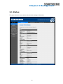
3.1 STATU S ............................................................................................................................................... 20
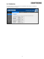
3.2 STATISTICS ......................................................................................................................................... 21
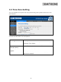
3.3 TIME ZONE SETTING .......................................................................................................................... 22
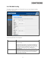
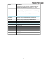
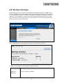
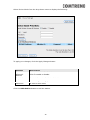
3.4 TR-069 CONFIG ................................................................................................................................. 23
1.5 WIFIXTEND CONFIG ................................................................................................................. 25
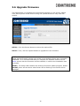
3.6 UPGRADE FIRMWARE ......................................................................................................................... 26
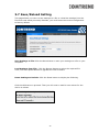
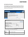
3.7 SAV E /RELOAD SETTING ..................................................................................................................... 27
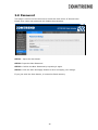
3.8 PASSWORD ......................................................................................................................................... 28
3.9 LOGOUT ............................................................................................................................................. 29
CHAPTER 4 5GHZ SETTINGS ............................................................................................................. 30
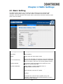
4.1 BASIC SETTING .................................................................................................................................. 30
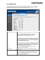
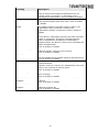
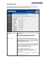
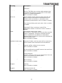
4.2 ADVANCED ........................................................................................................................................ 32
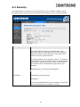
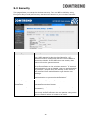
4.3 SECURITY .......................................................................................................................................... 34
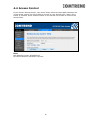
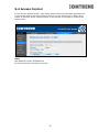
4.4 ACCESS CONTROL ............................................................................................................................. 35
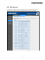
4.5 SITE SURVEY ..................................................................................................................................... 36
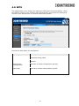
4.6 WPS .................................................................................................................................................. 37
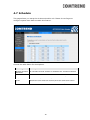
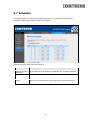
4.7 SCHEDULE ......................................................................................................................................... 38
4.8 AIRTIME FAIRNESS ............................................................................................................................ 39
CHAPTER 5 2.4GHZ SETTINGS .......................................................................................................... 41
5.1 BASIC SETTING .................................................................................................................................. 41
5.2 ADVANCED ........................................................................................................................................ 43
5.3 SECURITY .......................................................................................................................................... 45
5.4 ACCESS CONTROL ............................................................................................................................. 46
5.5 SITE SURVEY ..................................................................................................................................... 47
5.6 WPS .................................................................................................................................................. 49
5.7 SCHEDULE ......................................................................................................................................... 50
5.8 AIRTIME FAIRNESS ............................................................................................................................ 51
CHAPTER 6 TCP/IP ................................................................................................................................ 53
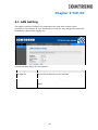
4.1 LAN SETTING .................................................................................................................................... 53
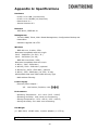
APPENDIX A: SPECIFICATIONS ........................................................................................................ 54
The setup images used in this manual are for reference only. The contents of these
images may vary according to firmware version. The official image contents are
based on the newest firmware version.

6
Chapter 1 Quick Installation
1. Package Contents
- WAP-5903 Wireless Mesh Extender
- Quick Installation Guide (QIG)
- Power Adapter
- Ethernet Cable
2. System Requirements
l Computer or network devices with wired or wireless network interface
card.
l Any connected devices must feature a network port.
l Web browser (Microsoft Internet Explorer 8.0 or above, Google Chrome
web browser, Opera web browser, or Safari web browser).
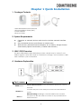
3. WAP-5903 Overview
The WAP-5903 Wireless Mesh Extender provides a simple way to “extend” your
wireless signal to areas with weak or nonexistent coverage, and to build-up a WiFi
mesh network in your home/office.
4. Hardware Explanation
Port / Button
Description
RESET Button
Factory Reset Function: Press and hold this button for over 10
seconds
UPLINK Port
Connect this port to the LAN port of the home broadband
router
Ethernet Pairing: Working in Comtrend WiFi mesh scenario
LAN Port
This port can also be used to connect to a pc/notebook for
Internet access

7
LED Explanation
LED Color
LED Status
Description
Green
On
The device is connected via Ethernet cable
Blinking
The mesh system is processing
Blue
On
The device is connected to WiFi, and the
connection quality is GOOD
Blinking
The device is booting up
Red
On
The device is connected to WiFi, and the
connection quality is WEAK
Blinking
The mesh system is processing
Green & Blue
Blinking
1. The device is standing by after booting up
2. The device lost the uplink connection
Green & Blue & Red
Blinking
1. The device is under firmware upgrade
2. The device is under reset to default process

8
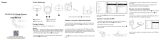
Quick Install Guide
WAP-5903 AC1200 Dual Band WiFi Mesh-Enhanced Extender
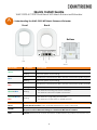
Understanding the WAP-5903 WiFi Mesh-Enhanced Extender
LED Color
LED Status
Description
Green
On
The device is connected via Ethernet cable
Blinking
The mesh system is processing
Blue
On
The device is connected to WiFi, and the connection quality is good
Blinking
The mesh system is processing
Red
On
The device is connected to WiFi, and the connection quality is weak
Blinking
The mesh system is processing
Green & Blue
Blinking
1. The device is booting up and on stand-by
2. The device has lost the uplink connection
Green & Blue &
Red
Blinking
1. The device is upgrading the firmware
2. The device is under reset to default process
Port/Button
Description
Reset
Factory Reset Function: Press and hold this button for over 10 seconds
UPLINK
Connect this port to the LAN port of the Comtrend Gateway/modem/router.
This port it used for Ethernet Pairing in a Comtrend WiFi mesh scenario.
LAN
Optional: Use this port to connect an Internet- enabled device (e.g. laptop, set-top-box, etc.).
Ethernet Port
A
Back
Bottom
RESET
Front
LED

9
Choose One
Scenario!I:
Setup with a Comtrend Gateway that supports WifiXtend2.0™
(Continue to Step B)
Scenario II:
Setup with either a non-Comtrend Gateway or
a Comtrend Gateway that does not support WifiXtend2.0™
(Continue to Step E)
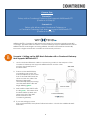
WifiXtend2.0™ is Comtrend’s WiFi Mesh technology for enhanced whole-home WiFi
coverage. The WAP-5903 and select Comtend Gatways support WifiXtend2.0™. When
WifiXtend2.0™ technologies are being utilized, the WiFi network will automatically
become a single network with one SSID and Password per band.
Scenario I: Setting up the WiFi Mesh Extender with a Comtrend Gateway
that Supports WifiXtend2.0™
1. Use the included Ethernet cable to connect one end into the LAN port of the
Comtrend Gateway that supports WifiXtend2.0™ and the other
end into the UPLINK port of
the WAP-5903.
2. Power on the WAP-5903 by
connecting one end of the
Power Adapter into the Power
Port of the WAP-5903 and the
other end into an outlet. The
Ethernet Pairing will
automatically start processing
and the WAP-5903’s LED will
begin blinking green.
3. Wait until the WAP-5903’s LED
is solid green. This means that
the WAP-5903 is paired and
grouped in the same WiFi
mesh network as the
Comtrend gateway.
4. If you are setting up more
than one WAP-5903, then please follow instructions 1-3 with the additional WAP-
5903 units.
B
Comtrend Gateway
WAP-5903
Power Plug
Ethernet Cable

10
Deploy the WiFi Mesh Extender
5. After the WAP-5903 is paired, move it to the nearest outlet where additional WiFi
coverage is needed. Once it is plugged in, wait for the LED to light up solid blue,
which means it is ready.
The WiFi Mesh Network is Ready to Use!
6. The WiFi mesh network is automatically using the original WiFi configuration on the
Comtrend Gateway. If you would like to further change the network settings, then
please refer to the Comtrend Gateway’s User Manual to make changes directly to
the Gateway.
Scenario II: Setting up the WiFi Mesh Extender with a Non-Comtrend
Gateway/Comtrend Gateway that does not Support WifiXtend2.0™.
Note: This scenario requires at least two WAP-5903 units to create a connection.
LED
Description
Solid
Blue
The WAP-5903 is placed in an ideal location
and is receiving a good WiFi signal.
Solid
Red
The WAP-5903 is placed too far away from
the Comtrend Gateway, and is receiving a
weak WiFi signal. Action Required: Move
the WAP-5903 closer to the Comtrend
Gateway.
D
C
E

11
1. Optional: Disable the WiFi on the non-Comtrend modem/router. This will help
improve the performance of the WiFi Mesh Extender and avoid confusing the
Internet-enabled devices.
2. Use the included Ethernet
cable to connect one end
into the LAN port of the
existing home modem/router
and the other end into the
UPLINK port of the first WAP-
5903.
3. Power on this WAP-5903 by
connecting one end of the
Power Adapter into the Power
Port of the WAP-5903 and the
other end into an outlet.
Setup the WiFi Network
4. You can now use your computer’s wireless configuration utility to
search for a Wireless Network name such as: Extender2368 or
Extender2368-5G. (The default SSID of this extender device is
‘Extender2368’, and 2368 is for reference. It is the last 4 digits of
the device’s MAC number.)
5. When you are prompted to input the security key, the WiFi Key
(password) can be found on the label at the back of the WAP-
5903 device.
WAP-5903
Power Plug
Ethernet Cable
Existing Modem/Router
F

12
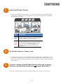
6. Click the OK button to connect to the network.
7. Open your web browser, and input ‘http://extender-setup/’ in the address bar.
8. The system will prompt you to input the username and password. Default username
is ‘root’ and password is ‘12345’. Click the OK button to continue.
9. After logging into the Web page, input the new SSID for both the 2.4GHz and 5GHz
fields. The user can setup a new password by inputting it in both the Key fields. Click
the Apply/Save button to complete setup.

13
10. After applying the wireless setting the WAP-5903 will reboot. When the WAP-5903’s
LED is solid green it means it is ready.
11. You can now connect the additional WAP-5903. Power on the additional WAP-
5903 by connecting one end of the Power Adapter into the Power Port of the
WAP-5903 and the other end into an outlet. The Ethernet Pairing will automatically
start processing and the WAP-5903’s LED will begin blinking green.
12. Wait until the WAP-5903’s LED is solid green. This means that the WAP-5903 is
paired and grouped in the same WiFi mesh network as the first WAP-5903.
13. You can now move the additional WAP-5903 extender to the nearest outlet where
more WiFi coverage is needed. Once plugged in, wait for the LED to light up solid
blue, which means it is ready.

14
14. Repeat steps 11-13 to add more WAP-5903 extenders to the mesh
network.
The WiFi Mesh Network is Ready to Use!
FOR MORE HELP: For instructions on advanced features, FAQ, etc., please visit our
online Product Webpage.
For more information:
YouTube: https://www.youtube.com/user/ComtrendConnection
Facebook: https://facebook.com/Comtrend
Website: http://us.comtrend.com/
Support: Visit our website or call (949) 753-9640
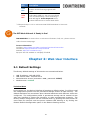
Chapter 2: Web User Interface
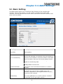
2.1 Default Settings
The factory default settings of this device are summarized below.
• LAN IP address: 192.168.2.252
• LAN subnet mask: 255.255.255.0
• Administrative access (username: root , password: 12345)
• WLAN access: enabled
Technical Note
During power on, the device initializes all settings to default values. It will then read
the configuration profile from the permanent storage section of flash memory. The
default attributes are overwritten when identical attributes with different values are
configured. The configuration profile in permanent storage can be created via the
web user interface or telnet user interface, or other management protocols. The
factory default configuration can be restored either by pushing the reset button for
more than five seconds until the power indicates LED blinking or by clicking the
Restore Default Configuration option in the Restore Settings screen.
LED
Description
Solid
Blue
The WAP-5903 is placed in an ideal
location and is receiving a good WiFi
signal.
Solid
Red
The WAP-5903 is placed too far away from
the first WAP-5903 (i.e. the one connected
to the modem/router), and is receiving a
weak WiFi signal. Action Required: Move
the WAP-5903 closer to the first WAP-5903.
G

15

16
2.2 IP Configuration
DHCP MODE
When the WAP-5903 powers up, the onboard DHCP server will switch on. Basically,
the DHCP server issues and reserves IP addresses for LAN devices, such as your
PC.
To obtain an IP address f r om the DCHP server, f o l low the steps provided below.
NOTE: The following procedure assumes you are running Windows. However,
the general steps involved are similar for most operating systems (OS).
Check your OS support documentation for further details.
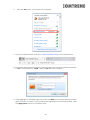
STEP 1: From the Network Connections window, open Local Area Connection (You
may also access this screen by double-clicking the Local Area Connection
icon on your taskbar). Click the Properties button.
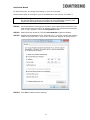
STEP 2: Select Internet Protocol (TCP/IP) and click the Properties button.
STEP 3: Select Obtain an IP address automatically as shown below.
STEP 4: Click OK to submit these settings.
If you experience difficulty with DHCP mode, you can try static IP mode instead.

17
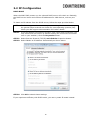
STATIC IP MODE
In static IP mode, you assign IP settings to your PC manually.
Follow these steps to configure your PC IP address to use subnet 192.168.2.x.
NOTE: The following procedure assumes you are running Windows. However,
the general steps involved are similar for most operating systems (OS).
Check your OS support documentation for further details.
STEP 1: From the Network Connections window, open Local Area Connection (You
may also access this screen by double-clicking the Local Area Connection
icon on your taskbar). Click the Properties button.
STEP 2: Select Internet Protocol (TCP/IP) and click the Properties button.
STEP 3: Change the IP address to the 192.168.2.x (1<x<252) subnet with subnet
mask of 255.255.255.0. The screen should now display as shown below.
STEP 4: Click OK to submit these settings.

18
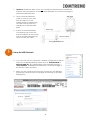
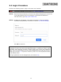
2.3 Login Procedure
Perform the following steps to login to the web user interface.
NOTE: The default settings can be found in 2.1 Default Settings.
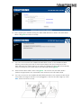
STEP 1: Start the Internet browser and enter the default IP address for the device
in the Web address field. For example, if the default IP address is
192.168.2.252, type http://192.168.2.252.
STEP 2: A dialog box will appear, s u c h a s t h e o n e b e l o w. Enter the default
username and password, as defined in section 2.1 Default Settings.
Click OK to continue.
NOTE: If you can’t see the web management interface, and you’re being
prompted to input user name and password again, it means you didn’t input
username and password correctly. Please retype user name and password
again. If you’re certain about the user name and password you type are correct,
please go to section 3.7 to perform a factory reset or to set the password back
to the default value.
The login password can be changed later (see section3.8).

19
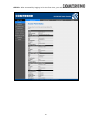
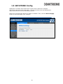
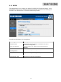
STEP 3: After successfully logging in for the first time, you will reach this screen.
La page est en cours de chargement...
La page est en cours de chargement...
La page est en cours de chargement...
La page est en cours de chargement...
La page est en cours de chargement...
La page est en cours de chargement...
La page est en cours de chargement...
La page est en cours de chargement...
La page est en cours de chargement...
La page est en cours de chargement...
La page est en cours de chargement...
La page est en cours de chargement...
La page est en cours de chargement...
La page est en cours de chargement...
La page est en cours de chargement...
La page est en cours de chargement...
La page est en cours de chargement...
La page est en cours de chargement...
La page est en cours de chargement...
La page est en cours de chargement...
La page est en cours de chargement...
La page est en cours de chargement...
La page est en cours de chargement...
La page est en cours de chargement...
La page est en cours de chargement...
La page est en cours de chargement...
La page est en cours de chargement...
La page est en cours de chargement...
La page est en cours de chargement...
La page est en cours de chargement...
La page est en cours de chargement...
La page est en cours de chargement...
La page est en cours de chargement...
La page est en cours de chargement...
La page est en cours de chargement...
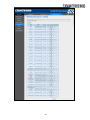
-
 1
1
-
 2
2
-
 3
3
-
 4
4
-
 5
5
-
 6
6
-
 7
7
-
 8
8
-
 9
9
-
 10
10
-
 11
11
-
 12
12
-
 13
13
-
 14
14
-
 15
15
-
 16
16
-
 17
17
-
 18
18
-
 19
19
-
 20
20
-
 21
21
-
 22
22
-
 23
23
-
 24
24
-
 25
25
-
 26
26
-
 27
27
-
 28
28
-
 29
29
-
 30
30
-
 31
31
-
 32
32
-
 33
33
-
 34
34
-
 35
35
-
 36
36
-
 37
37
-
 38
38
-
 39
39
-
 40
40
-
 41
41
-
 42
42
-
 43
43
-
 44
44
-
 45
45
-
 46
46
-
 47
47
-
 48
48
-
 49
49
-
 50
50
-
 51
51
-
 52
52
-
 53
53
-
 54
54
-
 55
55


Comtrend Corporation WAP-5903 Manuel utilisateur
- Catégorie
- Points d'accès WLAN
- Taper
- Manuel utilisateur
dans d''autres langues
Documents connexes
Autres documents
-
VTech VNT832 Manuel utilisateur
-
-
Yamaha YWA-10 Manuel utilisateur
-
 IT Works 500MBPS X2 WIFI/2XRJ45 Le manuel du propriétaire
-
 KE2 Case Controller Air Manuel utilisateur
-
 REYEE REX12 WiFi Extender Booster Signal Repeater Manuel utilisateur
-
Sercomm ADC-W115C Manuel utilisateur
-
 REYEE RG-REX12 Manuel utilisateur
-
Tenda A15 Guide d'installation
-
 IT Works 500MBPS X2 WIFI/2XRJ45 Le manuel du propriétaire


