
INSTRUCTION MANUAL
COLLATOR
DSC-10/60i
Be sure to read this manual prior to use.
Please leave this manual at the site of use for easy reference.

Introduction
Thank you for purchasing a Duplo product.
Be sure to read this manual prior to using the product.
After reading, leave the manual at the site of use for easy reference whenever questions related to the
product arise in the future.
Symbols
In this manual, several symbols are used to indicate important warnings. Please make sure to read
instructions accompanied by these symbols. These symbols have the following
meanings.
Describes instructions which must be followed in use.
Be sure to read the instructions to avoid problems due to incorrect operations.
Indicates supplementary or useful information.
Describes names of related items and supplementary instructions.
Trademark
The product name and company name used in this manual are trademarks or registered trademarks of the
respective companies.

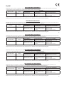
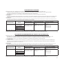
DECLARATION OF CONFORMITY
Duplo Corporation, located at 1-6, Oyama 4-chome, Chuo-ku, Sagamihara, Kanagawa 252-5280, Japan, declares that the product (or products)
complies with the provisions dened in the regulations. The reference table is mentioned below.
Name of product Model
Regulation
Machinery Directive
2006/42/EC under
Low Voltage Directive
2006/95/ECunder
Electromagnetic Compatibility
Directive 2004/108/EC under
Collator DSC-10/60 EN1010-1: 2004 + A1: 2010
EN1010-4: 2004 + A1: 2009
EN60204-1: 2006 + A1: 2009
IEC60950-1: 2005 + A1: 2009
including EN60950-1: 2006 +
A11: 2009 + A1: 2010 + A12: 2011
deviations
EN61000-3-2: 2006 + A1: 2009 + A2: 2009
EN61000-3-3: 2008
EN61000-6-2: 2005
EN61000-6-4: 2007 + A1: 2011
Keeper of the technical le in the European Community:
Duplo International Ltd, Automated Precision House, Hamm Moor Lane, Addlestone, Surrey, KT15 2SD, United Kingdom
En
KONFORMITÄTSERKLÄRUNG
Die Duplo Corporation mit Sitz in 1-6, Oyama 4 chome, Chuo-ku, Sagamihara, Kanagawa 252-5280 Japan, erklärt hiermit, dass das Produkt (oder die
Produkte) die in den Vorschriften denierten Bestimmungen erfüllt. Die Bezugstabelle ist unten aufgeführt.
Bezeichnung des
Produkts
Modell
Richtlinie
Maschinenrichtlinie
2006/42 EG unter
Niederspannungsrichtlinie
2006/95/EG unter
Richtlinie zur elektromagnetischen
Verträglichkeit 2004/108/EG unter
Zusammentragmaschine DSC-10/60 EN1010-1: 2004 + A1: 2010
EN1010-4: 2004 + A1: 2009
EN60204-1: 2006 + A1: 2009
IEC60950-1: 2005 + A1: 2009
including EN60950-1: 2006 +
A11: 2009 + A1: 2010 + A12: 2011
deviations
EN61000-3-2: 2006 + A1: 2009 + A2: 2009
EN61000-3-3: 2008
EN61000-6-2: 2005
EN61000-6-4: 2007 + A1: 2011
Inhaber der technischen Datei in der Europäischen Gemeinschaft:
Duplo International Ltd, Automated Precision House, Hamm Moor Lane, Addlestone, Surrey, KT15 2SD, United Kingdom
Ge
DECLARATION DE CONFORMITE
Duplo Corporation, dont le siège est situé au 1-6, Oyama 4-chome, Chuo-ku, Sagamihara, Kanagawa 252-5280, Japon, déclare que le ou les produits
sont conformes aux dispositions dénies par la réglementation. Un tableau de référence est proposé ci-dessous.
Nom du produit Modèle
Réglementation
Directive Machines
2006/42/CE en application
de la
Directive Basse tension
2006/95/CE en application
de la
Directive sur la compatibilité
électromagnétique 2004/108/CE
en application de
Assembleuse DSC-10/60 EN1010-1: 2004 + A1: 2010
EN1010-4: 2004 + A1: 2009
EN60204-1: 2006 + A1: 2009
IEC60950-1: 2005 + A1: 2009
including EN60950-1: 2006 +
A11: 2009 + A1: 2010 + A12: 2011
deviations
EN61000-3-2: 2006 + A1: 2009 + A2: 2009
EN61000-3-3: 2008
EN61000-6-2: 2005
EN61000-6-4: 2007 + A1: 2011
Conservateur du dossier technique dans la Communauté Européenne :
Duplo International Ltd, Automated Precision House, Hamm Moor Lane, Addlestone, Surrey, KT15 2SD, United Kingdom
Fr
DICHIARAZIONE DI CONFORMITÁ
Duplo Corporation, sita a 1-6, Oyama 4-chome, Chuo-ku, Sagamihara, Kanagawa 252-5280, Giappone, dichiara che il prodotto (o i prodotti) è/sono
conforme/i ai requisiti deniti dalle norme sottoelencate. La tabella di riferimento è riportata qui di seguito.
Nome del prodotto Modello
Direttiva Bassa Tensione
Direttiva sui macchinari
2006/42/CE in base a
Direttiva 2006/95/CE relativa
alle apparecchiature a bassa
tensione
Direttiva di compatibilità
elettromagnetica 2004/108/CE
in base a
Fascicolatore DSC-10/60 EN1010-1: 2004 + A1: 2010
EN1010-4: 2004 + A1: 2009
EN60204-1: 2006 + A1: 2009
IEC60950-1: 2005 + A1: 2009
including EN60950-1: 2006 +
A11: 2009 + A1: 2010 + A12: 2011
deviations
EN61000-3-2: 2006 + A1: 2009 + A2: 2009
EN61000-3-3: 2008
EN61000-6-2: 2005
EN61000-6-4: 2007 + A1: 2011
Responsabile della documentazione tecnica all’interno della Comunità Europea:
Duplo International Ltd, Automated Precision House, Hamm Moor Lane, Addlestone, Surrey, KT15 2SD, United Kingdom
It
DECLARACIÓN DE CONFORMIDAD
Duplo Corporation, con domicilio en 1-6, Oyama 4-chome, Chuo-ku, Sagamihara, Kanagawa 252-5280, Japón, declara que el producto (o los
productos) cumple con las disposiciones previstas en los reglamentos. Seguidamente se indica la tabla de referencia.
Nombre del producto Modelos
Reglamentación - Reglamentaciones
Directiva sobre máquinas
2006/42/CE, según
Directiva sobre baja tensión
2006/95/CE, según
Directiva sobre compatibilidad
electromagnética 2004/108/CE,
según
Clasicador DSC-10/60 EN1010-1: 2004 + A1: 2010
EN1010-4: 2004 + A1: 2009
EN60204-1: 2006 + A1: 2009
IEC60950-1: 2005 + A1: 2009
including EN60950-1: 2006 +
A11: 2009 + A1: 2010 + A12: 2011
deviations
EN61000-3-2: 2006 + A1: 2009 + A2: 2009
EN61000-3-3: 2008
EN61000-6-2: 2005
EN61000-6-4: 2007 + A1: 2011
Depositario del archivo técnico en la Comunidad Europea:
Duplo International Ltd, Automated Precision House, Hamm Moor Lane, Addlestone, Surrey, KT15 2SD, United Kingdom
Sp
For EU

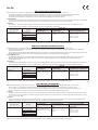
DECLARATION OF INCORPORATION
Duplo Corporation, located at 1-6, Oyama 4-chome, Chuo-ku, Sagamihara, Kanagawa 252-5280, Japan, declares:
• the essential requirements of the Machinery Directive are applied to the product (or products) mentioned in the table below and;
• the product (or products) complies with the provisions dened in the regulations mentioned in the table below and;
• the technical documentation is compiled in accordance with the Machinery Directive Annex VII part B;
and undertakes:
• to transmit relevant information of the product (or products) by appropriate method in response to reasoned request by the national authorities.
However that transmission shall be without prejudice to our intellectual property rights of the product (or products);
and states:
• the product (or products) is partly completed machinery and must not be put into service until the nal machinery into which it is to be
incorporated has been declared in conformity with the provisions of the Machinery Directive.
Name of product Model
Regulation
Machinery Directive
2006/42/EC under
Low Voltage Directive
2006/95/EC under
Electromagnetic Compatibility
Directive 2004/108/EC under
Collator Accessories PC CONTROLLER
(IF board, PC bracket)
EN1010-1: 2004 + A1: 2010
EN1010-4: 2004 + A1: 2009
EN60204-1: 2006 + A1: 2009
IEC60950-1: 2005 including
EN60950-1: 2006 + A11: 2009
deviations
EN61000-3-2: 2006 + A1: 2009 + A2:
2009
EN61000-3-3: 2008
EN61000-6-2: 2005
EN61000-6-4: 2007
D-PORT CONVERTER
LUL-HM
BRIDGE
ULTRASONIC SENSOR KIT
Keeper of the technical le in the European Community:
Duplo International Ltd, Automated Precision House, Hamm Moor Lane, Addlestone, Surrey, KT15 2SD, United Kingdom
En
ERKLÄRUNG DER AMTLICHEN EINTRAGUNG
Die Duplo Corporation mit Sitz in 1-6, Oyama 4 chome, Chuo-ku, Sagamihara, Kanagawa 252-5280 Japan, erklärt hiermit:
• alle wesentlichen Erfordernisse der Maschinenrichtlinie sind auf das in der untenstehenden Tabelle genannte Produkt (oder die Produkte)
angewendet worden, und
• das Produkt (oder die Produkte) erfüllt die Bestimmungen, die in den in der untenstehenden Tabelle genannten Vorschriften deniert sind, und
• die technische Dokumentation ist entsprechend der Maschinenrichtlinie Anhang VII Teil B zusammengestellt;
und verpichtet sich:
• auf begründete Anfragen der nationalen Behörden sachdienliche Informationen über das Produkt (die Produkte) mittels einer geeigneten
Methode zu liefern. Die Übergabe erfolgt jedoch so, dass unsere geistigen Eigentumsrechte am Produkt (oder den Produkten) nicht
beeinträchtigt werden,
und erklärt:
• das Produkt (oder die Produkte) ist ein Teil einer nicht vollständigen Maschinenanlage und darf so lange nicht in Betrieb genommen werden, bis
die komplette Maschinenanlage, in die es eingebaut wurde, oziell als mit der Maschinenrichtlinie übereinstimmend erklärt worden ist.
Bezeichnung des Produkt Modell
Richtlinie
Maschinenrichtlinie
2006/42 EG unter
Niederspannungsrichtlinie
2006/95/EG unter
Richtlinie zur elektromagnetischen
Verträglichkeit 2004/108/EG unter
Zubehör der
Zusammentragmaschine
PC CONTROLLER
(IF board, PC bracket
EN1010-1: 2004 + A1: 2010
EN1010-4: 2004 + A1: 2009
EN60204-1: 2006 + A1: 2009
IEC60950-1: 2005 einschließlich
Abweichungen der
EN60950-1: 2006 + A11: 2009
EN61000-3-2: 2006 + A1: 2009 + A2:
2009
EN61000-3-3: 2008
EN61000-6-2: 2005
EN61000-6-4: 2007
D-PORT CONVERTER
LUL-HM
BRIDGE
ULTRASONIC SENSOR KIT
Inhaber der technischen Datei in der Europäischen Gemeinschaft:
Duplo International Ltd, Automated Precision House, Hamm Moor Lane, Addlestone, Surrey, KT15 2SD, United Kingdom
Ge
DECLARATION D’INTEGRATION
Duplo Corporation, dont le siège social est situé au 1-6, Oyama 4-chome, Chuo-ku, Sagamihara, Kanagawa 252-5280, Japon, déclare :
• que les exigences essentielles de la Directive Machines sont appliquées au(x) produit(s) mentionné(s) dans le tableau ci-après,
• que le produit ou les produits sont conformes aux dispositions dénies par la réglementation mentionnée dans le tableau ci-après, et
• que la documentation technique a été réalisée conformément à l’Annexe VII partie B de la Directive Machines,
s’engage :
• à communiquer des informations pertinentes sur le ou les produits par un mode de transmission adapté en réponse à toute demande motivée
des autorités nationales. Toutefois, la communication de ces informations sera sans préjudice de nos droits de propriété intellectuelle en ce qui
concerne le ou les produits ;
et précise :
• que le ou les produits sont des machines en partie achevées et qu’ils ne doivent pas être mis en service avant que la machine dénitive dans
laquelle ils doivent être intégrés ait été déclarée conforme aux dispositions de la Directive Machine.
Nom du produit Modèle
Réglementation
Directive Machines
2006/42/CE en application
de la
Directive Basse tension
2006/95/CE en application
de la
Directive sur la compatibilité
électromagnétique 2004/108/CE en
application de
Accessoires de la relieuse PC CONTROLLER
(IF board, PC bracket)
EN1010-1: 2004 + A1: 2010
EN1010-4: 2004 + A1: 2009
EN60204-1: 2006 + A1: 2009
IEC 60950-1: 2005, dérogations
selon
EN60950-1: 2006 + A11: 2009
incluses
EN61000-3-2: 2006 + A1: 2009 + A2:
2009
EN61000-3-3: 2008
EN61000-6-2: 2005
EN61000-6-4: 2007
D-PORT CONVERTER
LUL-HM
BRIDGE
ULTRASONIC SENSOR KIT
Conservateur du dossier technique dans la Communauté Européenne :
Duplo International Ltd, Automated Precision House, Hamm Moor Lane, Addlestone, Surrey, KT15 2SD, United Kingdom
Fr
For EU

DICHIARAZIONE DI ISCRIZIONE
Duplo Corporation, sita a 1-6, Oyama 4-chome, Chuo-ku, Sagamihara, Kanagawa 252-5280, Giappone, dichiara che:
• i requisiti fondamentali della Direttiva sui macchinari sono applicati al prodotto (o prodotti) menzionato/i nella seguente tabella e
• il prodotto (o prodotti) è/sono conforme/i ai requisiti deniti nelle norme sottoelencate e;
• la documentazione tecnica è stata compilata conformemente alla Direttiva sui Macchinari Appendice VII parte B;
e si impegna a:
• trasmettere informazioni inerenti al prodotto (o sui prodotti) con un metodo appropriato in risposta a una richiesta logica da parte delle autorità
nazionali. La trasmissione di tali informazioni non deve comunque ledere i nostri diritti di proprietà intellettuale sul prodotto (o sui prodotti);
e specica che:
• il prodotto (o i prodotti) è/sono incompleto e non deve essere messo in funzione nché il macchinario nale in cui deve essere incorporato non
sia stato dichiarato conforme ai requisiti dichiarati dalla Direttiva sui Macchinari.
Nome del prodotto Modello
Direttiva Bassa Tensione
Direttiva sui macchinari
2006/42/CE in base a
Direttiva 2006/95/CE relativa
alle apparecchiature a bassa
tensione
Direttiva di compatibilità
elettromagnetica 2004/108/CE
in base a
Accessori del fascicolatore PC CONTROLLER
(IF board, PC bracket)
EN1010-1: 2004 + A1: 2010
EN1010-4: 2004 + A1: 2009
EN60204-1: 2006 + A1: 2009
IEC 60950-1: 2005 deviazioni
EN 60950-1: 2006 + A11: 2009
incluse
EN61000-3-2: 2006 + A1: 2009 + A2:
2009
EN61000-3-3: 2008
EN61000-6-2: 2005
EN61000-6-4: 2007
D-PORT CONVERTER
LUL-HM
BRIDGE
ULTRASONIC SENSOR KIT
Responsabile della documentazione tecnica all’interno della Comunità Europea:
Duplo International Ltd, Automated Precision House, Hamm Moor Lane, Addlestone, Surrey, KT15 2SD, United Kingdom
It
DECLARACIÓN DE INCORPORACIÓN DEL PRODUCTO (O LOS PRODUCTOS)
Duplo Corporation, con domicilio en 1-6, Oyama 4-chome, Chuo-ku, Sagamihara, Kanagawa 252-5280, Japón, declara que:
• el producto (o los productos) indicado en la siguiente tabla cumple con los requisitos esenciales de la Directiva sobre máquinas; y que
• el producto (o los productos) cumple con las disposiciones previstas en los reglamentos indicados en la siguiente tabla; y que
• la documentación técnica se ha recabado de conformidad con la Directiva sobre máquinas, anexo VII, parte B;
y se compromete a:
• comunicar información relevante sobre el producto (o los productos) por el método apropiado como respuesta a la solicitud debidamente
formulada por las autoridades nacionales. No obstante, dicha comunicación se efectuará sin perjuicio de nuestros derechos de propiedad
intelectual sobre el producto (o los productos);
y declara que:
• el producto (o los productos) es un aparato parcialmente terminado, por lo que el mismo no se deberá poner en funcionamiento hasta que se
haya declarado que el aparato nal en el que será incorporado cumple con las disposiciones previstas en la Directiva sobre máquinas.
Nombre del producto Modelos
Reglamentación - Reglamentaciones
Directiva sobre máquinas
2006/42/CE, según
Directiva sobre baja tensión
2006/95/CE, según
Directiva sobre compatibilidad
electromagnética 2004/108/CE,
según
Accesorios del clasicador PC CONTROLLER
(IF board, PC bracket)
EN1010-1: 2004 + A1: 2010
EN1010-4: 2004 + A1: 2009
EN60204-1: 2006 + A1: 2009
IEC60950-1: 2005, incluyendo
EN60950-1: 2006 + A11: 2009
modicadas.
EN61000-3-2: 2006 + A1: 2009 + A2:
2009
EN61000-3-3: 2008
EN61000-6-2: 2005
EN61000-6-4: 2007
D-PORT CONVERTER
LUL-HM
BRIDGE
ULTRASONIC SENSOR KIT
Depositario del archivo técnico en la Comunidad Europea:
Duplo International Ltd, Automated Precision House, Hamm Moor Lane, Addlestone, Surrey, KT15 2SD, United Kingdom
Sp

For EU
Disposal of Old Electrical & Electronic Equipment
This symbol (the symbol of the crossed out wheeled
bin) indicates that in European countries this product
should not be disposed of as household waste.
Please recycle where facilities exist by checking with
your local authority or supplier for recycling advice.
By ensuring this product is disposed of correctly
through proper treatment, recovery and recycling,
you will help prevent potential negative eects on the
environment and human health.
En
Entsorgung von alten elektrischen und
elektronischen Ausrüstungsteilen
Dieses Symbol (das Symbol mit dem durchgekreuzten
fahrbaren Müllbehälter) zeigt an, dass dieses Produkt
in europäischen Länden nicht als Haushaltsmüll
entsorgt werden darf. Bitte informieren Sie sich bei
Ihren örtlichen Behörden oder bei Ihrem Händler
hinsichtlich einer Empfehlung für die Entsorgung
und führen Sie die betreenden Teile dort, wo solche
Einrichtungen vorhanden sind, einem Recycling-
Prozess zu.
Indem sie sicherstellen, dass das betreende Produkt
durch richtige Behandlung, Rückführung und Recycling
entsorgt wird, tragen Sie dazu bei, möglichen negativen
Auswirkungen auf die Umwelt und die menschliche
Gesundheit vorzubeugen.
Ge
Elimination du matériel électronique et électrique
usagé
Ce symbole (une poubelle marquée d’une croix)
indique que dans les pays européens, ce produit ne
doit pas être éliminé comme des ordures ménagères.
Recyclez-le dans les sites adaptés qui vous seront
indiqués par les autorités locales ou renseignez-vous
auprès de votre fournisseur.
En veillant à ce que ce produit soit éliminé
correctement avec un traitement, une collecte et un
recyclage adaptés, vous contribuez à éviter son action
nocive potentielle sur l’ environnement et la santé
humaine.
Fr
Smaltimento di attrezzature elettriche ed
elettroniche consumate
Questo simbolo (il simbolo della pattumiera con rotelle
barrata) indica che nei paesi europei questo prodotto
non deve essere buttato nei rifiuti domestici.
Per favore smaltire in luogo addetto al riciclo, dove
esistente, chiedendo informazioni alle autorità locali o
a chi fornisce consulenza a proposito.
Garantendo uno smaltimento adeguato di questo
prodotto (trattamento, recupero e riciclo corretto),
aiuterete a prevenire eetti negativi sull’ambiente e
sulla salute dell’uomo.
It
Eliminación de residuos de aparatos eléctricos y
electrónicos
Este símbolo (un cubo de basura tachado) indica
que en los países europeos este producto no deberá
eliminarse como si se tratara de un residuo doméstico.
Solicite asesoramiento sobre reciclaje a las autoridades
locales o a su distribuidor, y siga la normativa en
materia de gestión medioambiental y reciclaje de este
tipo de residuos.
Si toma las medidas pertinentes para que este
producto se elimine mediante un tratamiento,
recuperación y reciclaje adecuados, contribuirá a evitar
posibles efectos negativos en el medio ambiente y la
salud humana.
Sp
For North America
Note:
This equipment has been tested and found to comply with the limits for a Class A digital device, pursuant
to Part 15 of the FCC Rules. These limits are designed to provide reasonable protection against harmful
interference when the equipment is operated in a commercial environment. This equipment generates, uses,
and can radiate radio frequency energy and, if not installed and used in accordance with the instruction
manual, may cause harmful interference to radio communications.
Operation of this equipment in a residential area is likely to cause harmful interference in which case the user
will be required to correct the interference at his own expense.

i
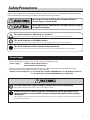
Safety Precautions
Safety Precautions
In this manual, operations and handling of the unit which are hazardous are described using the following
marks to prevent personal injury or property damage to the user and others.
Ignoring this mark could result in the possibility of
serious injury or even death.
Ignoring this mark could result in the possibility of injury
or physical damage.
This mark indicates a “Warning” or “Caution”.
A graphic may be shown inside the mark to describe the warning or caution more specically.
This mark indicates a forbidden action.
A graphic may be shown inside the mark to describe the forbidden action more specically.
This mark indicates actions that must be performed.
A graphic may be shown inside the mark to describe the action to be performed more specically.
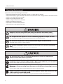
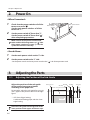
Power Supply
• Make sure the power supply used is always within the following range.
Power supply : 120 V AC, 60 Hz (North America)
220 to 240 V AC, 50/60 Hz (EU)
• When you power other appliances from the same AC outlet, make sure that the combined power
consumption does not exceed the power supply capacity.
Rated current, Rated power : 8.4 A, 960 W (Excl. D-PORT CONVERTER 7.9 A, 910 W)(North America)
5.3 A, 980 W (Excl. D-PORT CONVERTER 5.1 A, 930 W) (EU)
Use only the power supply voltage specied on the main nameplate.
Using other voltages could result in a re or an electrical shock.
Make sure that the combined power consumption of the appliances to be
connected does not exceed the capacity rating of the power outlets or plug
receptacles.
Exceeding the capacity rating could cause the power outlets, plug receptacles, or power extension cords to
overheat and catch a re.

ii
Safety Precautions
Operating Environment
Operate this unit in the following environment.
• where the temperature range is between 5 and 35°C (-10 to +50°C in storage)
• where the humidity range is between 20 and 85% RH (10 to 90% RH in storage, however no condensation)
• which is not subject to direct sunlight
• which is reasonably free from dust
• which is subject to little or no vibration
• which is free from air-borne salt
• where there are no harmful chemicals
• where the unit is not exposed to water
Keep this unit and the power cord away from heaters and heater vents.
Excessive heat could melt the cover or power cord covering, and result in a re or an electrical shock.
Do not place metal objects or vessels containing liquids on top of the unit.
The entry of any metal object or liquid could result in a re or an electrical shock.
Do not insert any metal or easily-combustible object inside this unit.
This could result in a re or an electrical shock.
Do not use ammable sprays inside or near the unit (e.g. when cleaning the
unit).
Such ammable gas may ignite and cause a re or combustion.
Do not install this unit in a location where there is excessive humidity or
where contact with water is possible.
Poor choice of location could result in deterioration of the insulation, a re or an electrical shock.
Install this unit on a level, stable stand or oor, with sucient space around it.
Failure to do so could result in the unit overturning and causing injury.
Disconnect the power plug from the power outlet before attempting to move
this unit.
Failure to do so could result in power cord damage, a re or an electrical shock.
Always disconnect the power plug from the power outlet when the unit is not
to be used for an extended period.
Failure to do so could result in a re due to leakage current if the insulation should deteriorate.

iii
Safety Precautions
Maintenance / Other
Do not damage the power cord or power plug.
Do not scratch, alter, bend, twist, pull or place heavy objects on the power cord or power plug.
This could result in damage, a re or an electrical shock.
Do not touch the power switch with wet hands.
Otherwise electric hazards may occur.
Do not remove the cover or back panel.
This unit contains high-voltage components that could cause an electrical shock.
Do not disassemble, modify or repair this unit.
There is a danger of re, electrical shock or injury.
Contact your dealer when repairs are necessary.
If any foreign object such as metal or liquid should enter this unit,
immediately turn the unit o at the power switch and disconnect the power
plug from the power outlet.
Failure to do so could result in a re or an electrical shock.
Contact your dealer immediately.
Before cleaning this unit, turn the unit o at the power switch and disconnect
the power plug from the power outlet.
Accidental operation of the unit during cleaning could result in injury.
Remove any dust that accumulates on the power plug prongs and the surface
of the plug from which the prongs extend.
Accumulated dust could result in a re.
Always grip the plug when disconnecting the power plug from the power
outlet.
Forcibly pulling on the power cord could cause damage, resulting in a re or an electrical shock.
Do not touch or insert foreign objects into any rotating part during operation.
This could result in injury.

iv
Safety Precautions
WARNING / CAUTION Labels
"WARNING" and "CAUTION" labels are pasted on the machine to ensure user safety.
Do not remove or change them.
When the labels become dirty or are lost, be sure to contact your dealer for a new one.
For EU

v
Safety Precautions
For North America

vi
Safety Precautions
Memo

vii
Contents
Contents
Safety Precautions .............................................i
Power Supply .................................................................................i
Operating Environment ...........................................................ii
Maintenance / Other ............................................................... iii
WARNING / CAUTION Labels ................................................iv
Chapter 1
Before Use
1. Features of This Machine ....................... 1-1
2. Names and Operation of Parts .............. 1-2
3. Names and Operation of Control
Panel ........................................................ 1-4
4. Accessory Parts ....................................... 1-5
5. Options .................................................... 1-6
6. Precautions on Use of Emergency Stop
Switch ...................................................... 1-6
Chapter 2
Operations
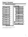
1. Operation Procedures ............................ 2-1
2. Power On ................................................. 2-2
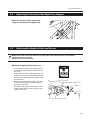
3. Adjusting the Parts ................................. 2-2
3-1. Adjusting the Position of the Sub-Guide .......2-2
3-2. Adjusting the Position of the Reject Tray
Stopper ........................................................................ 2-3
3-3. Adjusting the Height of the Level Sensor ...... 2-3
3-4. Adjusting the Separating Air .............................. 2-4
3-5. Adjusting the Height of the Separator ...........2-4
3-6. Adjusting the Strength of Separating Air ......2-5
3-7. Adjusting the Suction Box Shutter Bar ...........2-5
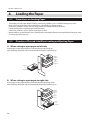
4. Loading the Paper .................................. 2-6
4-1. Precautions on Loading Paper ...........................2-6
4-2. Direction of Printed Side When Loading and
Ejecting Paper ...........................................................2-6
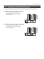
4-3. Loading Paper in Normal Collation
Operations ..................................................................2-7
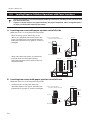
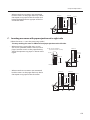
4-4. Loading Paper in Collation Operations with
Cover Insertions .......................................................2-8
4-5 Using the Paper Guide .........................................2-11
4-6. Using the Extension Tray ....................................2-13
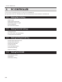
5. PC CONTROLLER ...................................2-14
5-1. Making Basic Setting ............................................2-14
5-2. Making Detailed Settings ...................................2-14
5-3. Setting the Paper Feed Tray...............................2-14
5-4. Setting the LUL-HM ..............................................2-14
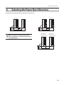
6. Selecting the Paper Eject Direction ....2-15
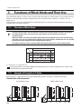
7. Functions of Block Mode and
Their Use ................................................2-16
7-1. Structure of Block Mode .....................................2-16
7-2. Example of Using the 1/2 Mode ......................2-16
7-3. Example of Using the 1/3 Mode ......................2-17
7-4. Example of Using the 1/4 Mode ......................2-18
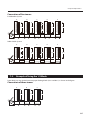
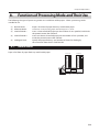
8.
Functions of Processing Mode and Their
Use ............................................................2-19
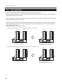
8-1. Normal Mode ..........................................................2-19
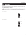
8-2. Alternate Mode ......................................................2-20
8-3. Interleaf Mode ........................................................2-21
9. Collation ................................................2-22
9-1. Checking the Paper Feeding .............................2-22
9-2. Start/Stop of Collation .........................................2-23
10. Waiting Mode ........................................2-24
10-1. When the Waiting Mode is Activated ............2-24
10-2. Canceling Waiting Mode ....................................2-25
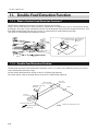
11. Double-Feed Detection Function .......2-26
11-1. What is Double-Feed Detection
Function ? .................................................................2-26
11-2. Double-Feed Detection Position ....................2-26
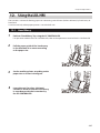
12.
Using the LUL-HM ........................................2-27
12-1. Hand Marry ..............................................................2-27
12-2. Hand Feed ................................................................2-28
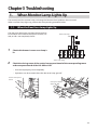
Chapter 3
Troubleshooting
1. When Monitor Lamp Lights Up ............. 3-1
1-1. When the Door Error Lamp Lights Up.............3-1
1-2. When the Conveyance Path Jam Lamp Lights
Up ...................................................................................3-2
1-3.
When the Double-Feed, Mis-Feed, and Jam Lamps
Blink Simultaneously .........................................................3-4
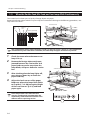
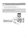
2.
Countermeasures Taken for Jam at Paper Feed
Inlet .........................................................................3-5
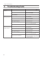
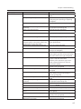
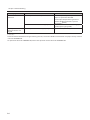
3. Troubleshooting Guide .......................... 3-6

viii
Contents
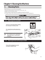
Chapter 4
Cleaning the Machine
1. Cleaning Parts ......................................... 4-1
1-1. Cleaning the Suction Belt.....................................4-1
1-2. Cleaning the Vertical Conveyance Belt ...........4-1
1-3.
Cleaning the Cconveyance Belt of the Horizontal
Conveyance Section ....................................................4-2
1-4. Cleaning the Conveyance Belt of the
LUL-HM ........................................................................4-2
1-5. Double-Feed Sensor ...............................................4-3
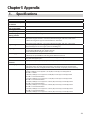
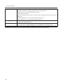
Chapter 5
Appendix
1. Specications .......................................... 5-1

1-1
Chapter1 Before Use
Chapter 1 Before Use
1. Features of This Machine
DSC-10/60i can be used with six units connected maximally, and can per-
form a large amount of collation work.
Paper is fed by using air belt suction method, and can be processed at a
high speed and properly without being damaged.
The following two paper processing modes are available.
[Block Mode]
Paper can be loaded while the machine is being operated to reduce operation time.
[Processing Mode]
Five types of collation methods (normal mode, alternate mode, interleaf mode 1, interleaf mode 2, and
intelligent feed) can be selected.
PC CONTROLLER(Option)(*
1
)
The DSC-10/60i can be operated on the PC monitor by installing the PC CONTROLLER to the PC in use.
(*
1
) The PC CONTROLLER is needed to use this machine.

1-2
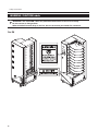
Chapter1 Before Use
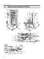
2. Names and Operation of Parts
[1]
[5]
[2]
[3]
[4]
[9]
[10]
[8]
[6]
[11] [13]
[15]
[16]
[17]
[20]
[7]
[21]
[12]
[23]
[14]
[18]
[24]
[22]
[19]

1-3
Chapter1 Before Use
No. Name Operation
[1] Control panel For details, refer to “3. Names and Operation of Control Panel” (p.1-4).
[2] Horizontal conveyance section Conveys the collated paper.
[3] Emergency stop switch Press this switch to stop operations in emergency. Normally, use the stop key
on the control panel to stop operations.
[4] Main power switch When pressed, the power turns ON and the machine sets into the standby
state.
[5] Power switch When connecting and using several towers together, the power of all the
towers can be turned ON and OFF using the switch of the rst tower (the
leftmost tower).
[6] Reject tray When feed error occurs, defected sets are ejected to this tray.
[7] Lifting unit Conveys the collated paper to the downstream unit.
[8] Hand marry Set paper here when feeding paper manually. Enables manual feed of set
consisting of up to 10 sheets of paper at a time.
[9] Vertical conveyance board Conveys the fed paper.
[10] Sub-guide Presses the edge of the paper being conveyed to prevent the paper from
rising.
[11] Long stack guide Used to feed paper of A4 size or more (paper length: 300 mm / 11.8 inches).
[12] Separator adjusting knob Used to adjust the position of the separator.
[13] Paper guide Presses the edge of the paper to hold the paper in place.
[14] Paper feed tray Used to load paper to be collated.
[15] Separating-air duct Blows out the air for separating paper loaded to the paper feed tray.
[16] Separator Used to prevent double-feed.
[17] Suction belt Sucks and conveys the paper.
[18] Level sensor Determines the height (interval between the paper and suction belt) of the
paper oated by the separating air.
[19] Level sensor adjusting knob Adjusts the interval between the paper and suction belt.
[20] Shutter Adjusts the amount of separating air blown out.
[21] Separating-air adjusting knob Used to adjust the position of the shutter.
[22] Suction box shutter bar Adjusts the range of suction.
[23] Separating-air adjusting lever Adjusts the strength of separating air.
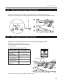
[24] Extension tray Used to load paper of 508 mm / 20.0 inches or longer (*1) by pulling out.
[6] to [8] are collectively called LUL-HM. [6] to [8] are optional products.
(*1) : The following paper length and width can be used.
• Length: up to 610 mm / 24.0 inches
• Width: 200 to 230 mm / 7.87 to 9.06 inches
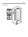
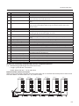
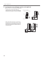
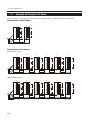
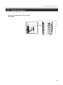
Name of collator (tower) connected
When using several towers together, the tower on the left side as seen from the control panel is Tower A and
those that follow are called Towers B, C, D, E, and F in order.
Tower A
Tower B Tower C Tower D Tower E
Tower F

1-4
Chapter1 Before Use
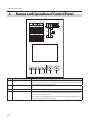
3. Names and Operation of Control Panel
[16] [15] [14] [13] [12] [11] [10]
[8]
[9]
[7]
[6]
[4]
[3][2][1]
[5]
No. Name Operation
[1] Paper lamp The lamp of the paper feed tray feeding paper lights up.
When a paper feed tray runs out of paper, the corresponding lamp of the paper
feed tray blinks and the machine stops.
[2] Double-feed lamp When paper of a paper feed tray is double-fed, the corresponding lamp lights
up.
[3] Mis-feed lamp When paper of a paper feed tray is mis-fed, the corresponding lamp lights up.
[4] Jam lamp When a paper feed tray jams, the corresponding lamp lights up.
Even when the machine is in the standby state if paper jams at the sensor, the
corresponding lamp lights up.
When paper jams during paper feed, remove the paper after the machine has
stopped. The lamp lit will start blinking.

1-5
Chapter1 Before Use
No. Name Operation
[5] Tower error lamp The lamp of the corresponding tower lights up when the following occurs in
that tower.
•The vertical conveyance board is open. •The emergency stop switch is pressed.
•There is no paper. •Paper feed errors occur.
•Paper jams in the paper conveyance path.
[6] Door error lamp The lamp of the corresponding tower lights up when the following occurs in
that tower.
•The vertical conveyance board is open. •The exterior cover is removed.
•The conveyance board of LUL-HM / LUR is open.
[7] Conveyance path jam lamp Lights up when paper jams in the conveyance path of a tower.
[8] Left connected unit error
lamp
Lights up when problems occur in the downstream unit connected to the left
side of the collator.
[9] Right connected unit error
lamp
Lights up when problems occur in the downstream unit connected to the right
side of the collator.
[10] Stop key Press this key to stop the machine.
[11] Start key Press this key for about one second to start the machine.
Also press this key to enter the waiting mode during processing.
[12] Operation lamp Lights up when the machine is ready or processing.
While the waiting mode is selected, the lamp continues to blink.
[13] Tray up key Press this key to raise all paper feed trays. Pressing this key while the paper feed
trays are rising stops the paper feed trays.
[14] Tray down key Press this key to lower all paper feed trays. Pressing this key while the paper
feed trays are descending stops the paper feed trays.
[15] Eject key The paper conveyance motor drives only while this key is pressed.
Press the eject key keeping tray down key pressed, the paper feed belt rotates
reversely . Remove the jammed paper at the paper feed inlet.
[16] Preset key Press this key for about one second whenever starting the collation process for
the rst time. Only one set is collated, and the used paper feed trays and paper
thickness are memorized. When changing the type of paper used and starting
collation again, be sure to press this key.
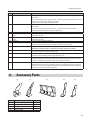
4. Accessory Parts
[1] [2] [3] [4] [5]
No. Name Qty.
[1] Movable Paper guide 3
[2] Paper guide 27
[3] Long stack guide 20
[4] Stack guide A 1
[5] Stack guide B 9

1-6
Chapter1 Before Use
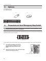
5. Options
PC CONTROLLER
[1] [2]
No. Name Qty.
[1] Protection key 1
[2] CD-R unit 1
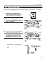
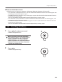
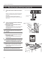
6. Precautions on Use of Emergency Stop Switch
Use the emergency stop switch to stop operations in emergency. In normal operations, use the
stop key on the control panel to stop operations.
Stopping operations using the emergency stop switch will light up the tower error lamp on the control panel
of the tower whose switch was pressed.
Tower error lamp
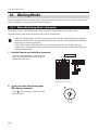
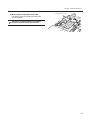
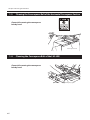
Set the machine back into the standby state as follows when the emergency stop switch has been pressed.
1
Pressing the emergency stop switch
may cause paper being processed to
remain in the machine. Remove this
paper.
Emergency stop switch
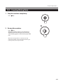
2
Rotate the emergency stop switch to the right
(clockwise direction) to clear it.
La page est en cours de chargement...
La page est en cours de chargement...
La page est en cours de chargement...
La page est en cours de chargement...
La page est en cours de chargement...
La page est en cours de chargement...
La page est en cours de chargement...
La page est en cours de chargement...
La page est en cours de chargement...
La page est en cours de chargement...
La page est en cours de chargement...
La page est en cours de chargement...
La page est en cours de chargement...
La page est en cours de chargement...
La page est en cours de chargement...
La page est en cours de chargement...
La page est en cours de chargement...
La page est en cours de chargement...
La page est en cours de chargement...
La page est en cours de chargement...
La page est en cours de chargement...
La page est en cours de chargement...
La page est en cours de chargement...
La page est en cours de chargement...
La page est en cours de chargement...
La page est en cours de chargement...
La page est en cours de chargement...
La page est en cours de chargement...
La page est en cours de chargement...
La page est en cours de chargement...
La page est en cours de chargement...
La page est en cours de chargement...
La page est en cours de chargement...
La page est en cours de chargement...
La page est en cours de chargement...
La page est en cours de chargement...
La page est en cours de chargement...
La page est en cours de chargement...
La page est en cours de chargement...
La page est en cours de chargement...
La page est en cours de chargement...
La page est en cours de chargement...
La page est en cours de chargement...
La page est en cours de chargement...
-
 1
1
-
 2
2
-
 3
3
-
 4
4
-
 5
5
-
 6
6
-
 7
7
-
 8
8
-
 9
9
-
 10
10
-
 11
11
-
 12
12
-
 13
13
-
 14
14
-
 15
15
-
 16
16
-
 17
17
-
 18
18
-
 19
19
-
 20
20
-
 21
21
-
 22
22
-
 23
23
-
 24
24
-
 25
25
-
 26
26
-
 27
27
-
 28
28
-
 29
29
-
 30
30
-
 31
31
-
 32
32
-
 33
33
-
 34
34
-
 35
35
-
 36
36
-
 37
37
-
 38
38
-
 39
39
-
 40
40
-
 41
41
-
 42
42
-
 43
43
-
 44
44
-
 45
45
-
 46
46
-
 47
47
-
 48
48
-
 49
49
-
 50
50
-
 51
51
-
 52
52
-
 53
53
-
 54
54
-
 55
55
-
 56
56
-
 57
57
-
 58
58
-
 59
59
-
 60
60
-
 61
61
-
 62
62
-
 63
63
-
 64
64


dans d''autres langues
- English: Duplo DSC-10/60i User manual
Documents connexes
Autres documents
-
Aiphone JF-2SD Installation & Operation Manual
-
 SMS Smart Media Solutions TT031003 Fiche technique
-
Philips PPX3614/EU Déclaration de conformité
-
Philips HDP1590/10 Déclaration de conformité
-
SolaHD SDN-P Le manuel du propriétaire
-
-
-
Blade 350 QX Guide de démarrage rapide
-
Emerson SDN 10-24-100c Manuel utilisateur
-
HP LaserJet Pro MFP M125 series Mode d'emploi
