Manhattan Comfort Eiffel 3-Piece Garage Set Assembly Manual
- Taper
- Assembly Manual

Ed. 001, 2022/06 - Manhattan Comfort.
888-230-2225
help@manhattancomfort.com
Model # 250BMC6, 250BMC8, 250BMC83, 250BMC84, 250BMC85
15
lb
33
lb
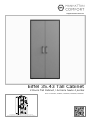
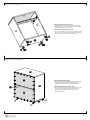
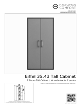
Eiffel 35.43 Tall Cabinet
2 Doors Tall Cabinet / Armoire haute 2 portes
The indicated values consider static weights and evenly distributed over the parts.
Les valeurs indiquées tiennent compte des poids statiques et uniformément répartis sur les pièces.
18
lb
15
lb
20
lb
3
lb

n.° ID
2
01
02
03
04
05
1
2
2
06 2
07 1
01
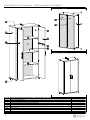
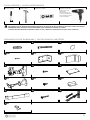
INCLUDED IN THE PACKAGE / INCLUS DANS LE PACKAGE
Parts identification (Description) / Identification des pièces (Description) Quantity / Quantité
Fixed Shelf / Étagère fixe
Side Panel / Panneau latéral
Door / Porte
REAR VIEW / VUE ARRIÈRE
FRONT VIEW / VUE DE FACE
FINAL APPEARANCE / APPARENCE FINALE
01
02
07
01
03
02
03
04
06
06
Plastic "H" Profile 1800mm / Profilé en "H" en plastique 1800mm
Top Panel and Base / Panneau du haut et Base
Back Panel / Panneau arrière
2
2
Removable Shelf / Étagère amovible
08 1
Metal Key Holder / Porte-clés en métal
02
05
05
08
04

3
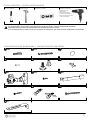
12x
A12x
B4x
C
!
IMPORTANT! Two people are recommended to assemble and install this product.
It is recommended to fix the cabinet on the wall with the anti-tipping bracket, to prevent accidental falls and damage.
IMPORTANT! Deux personnes sont recommandées pour assembler et installer ce produit.
Il est recommandé de fixer l'armoire au mur avec le support anti-basculement, pour éviter les chutes accidentelles et les dommages.
INCLUDED IN THE HARDWARE / INCLUS DANS LE MATÉRIEL
Simple hammer.
Marteau simple.
Manual screwdriver.
Tournevis manuel.
Electric drill and electric
screwdriver with drill
bit Ø10mm and
phillips tips.
Perceuse électrique
et tournevis électrique
avec foret Ø10mm pouce
et pointes phillips.
TOOLS NEEDED / OUTILS NÉCESSAIRES
Level indicator.
Indicateur de niveau.
62x
D4x
E8x
F
8x
G62x
H2x
I
4x
J1x
K1x
L
1x
M

4
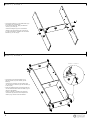
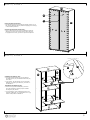
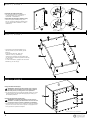
• Connect the Top Panel and Base (03) to
the Side Panels (02) with dowels (A) and
bolts (B).
Connectez les Panneau du haut et Base (03)
sur les Panneaux latéraux (02) des chevilles (A)
et des vis (B).
• Insert the plastic bushing and leveling base (E)
into the indicated holes under the Base (03), as
shown in the DETAIL 1.
Insérez la douille en plastique et la base de
nivellement (E) dans les trous indiqués sous
la Base (03), commé ilustré au DÉTAIL 1.
STEP 2 / ÉTAPE 2
STEP 1 / ÉTAPE 1
DETAIL 1 / DÉTAIL 1
!
• Connect the Shelf (01) to the Side Panels (02)
with dowels (A) and bolts (B).
At the end of the fixing, apply the adhesive
covers (C) on bolts (B).
Connectez l'Étagère (01) sur les Panneaux
latéraux (02) des chevilles (A) et des vis (B).
A la fin de la fixation, appliquez les couvercles
adhésifs (C) sur les vis (B).
02
01
03
03
02
01
02
03
02
02

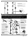
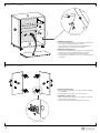
Installing the Shelves (05):
• Insert the metal brackets (F) into the holes in
the Side Panels (02) and install the Shelves (05)
over them.
• If you prefer, fix the Shelves (05) on the metal
brackets (F) applying the bolts (H), as shown in
the DETAIL 2.
Installation des Étagères (05):
• Insérez les supports métalliques (F) dans les
trous des Panneaux latéraux (02) et installez
les Étagères (05) dessus.
• Si vous préférez, fixez les Étagères (05) sur les
supports métaliques (F) en appliquant les vis (H),
comme indiqué dans le DÉTAIL 2.
STEP 4 / ÉTAPE 4
STEP 3 / ÉTAPE 3
DETAIL 2 / DÉTAIL 2
!
Fixing the Back Panels (04):
• Fix the Back Panels (04) by fitting the plastic profile (07) at
the junction between the two parts and applying the nails (D)
in the indicated positions.
Fixation des Panneaux arrière (04):
• Fixez le Panneaux arrière (04) en insérant le Profilé en
plastique (07) dans la couture entre les deux pièces et
en appliquant les clous (D) dans les positions indiquées.
01
02
5
02
05
05
03
03
05
02
07
04
03
02

STEP 6 / ÉTAPE 6
STEP 5 / ÉTAPE 5
6
Fixer and
adjustment bolts.
Vis de fixation
et réglage.
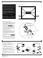
Installing the Doors (06):
• Fix the hinges connectors (G) of the
Doors (06) on the Side Panels (02)
with bolts (H), taking the markings in
these Panels (02) as a reference for
correct positioning. The hinge and its
connector includes two more bolts,
shown in DETAIL 5. Use these fixer
and adjustment bolts to tighten,
adjust and align the doors.
• Fix the metal key holder (08) on one
of the Doors with bolts (H).
Installation des Portes (06):
• Fixez les connecteurs des charnières
(G) des Portes (06) sur les Panneaux
latéraux (02) avec des vis (H), en
prenant les marques comme référence
pour un positionnement correct.
La charnière et son connecteur
comprennent deux autres vis,
illustrées dans le DÉTAIL 5. Utilisez
ces vis de fixation et réglage pour
serrer, régler et aligner les portes.
• Fixez le porte-clés en métal (08) sur
une des Portes, avec des vis (H).
01
06
DETAIL 3 / DÉTAIL 3
Preparing the Doors (06):
• Fix the hinges (G) with bolts (H) in the Doors (06),
as shown in the DETAIL 3.
• Fix the handle (I) in the Doors (06) with bolts (J).
Préparation des Portes (06):
• Fixez les charnières (G) avec les vis (H) dans les
Portes (06), comme indiqué dans le DÉTAIL 3.
• Fixez la poignée (I) dans les Portes (06) avec des
vis (J).
ATTENTION! Before to make the installation, check the conditions of the wall to anchor the cabinet and the existence and position of hydraulic, electrical and gas pipes,
avoiding damage to these structures when drilling the hole for applying the bushing (K) and the bolt (L) to fix the anti-tipping bracket (M).
The bushing (K) supplied with the product is for hollow walls or dry wall type. Check the type of the wall on which the installation will be made and, if necessary, look for more suitable
devices. To mark position and fix the cabinet on the wall, check the level of the entire assembly and the position of the feet in relation to the floor.
ATTENTION! Avant l'installation, vérifiez les conditions du mur pour ancrage de l'armoire, ainsi que l'existence et la position des conduites hydrauliques, électriques et
de gaz, en évitant d'endommager ces structures lors du perçage du trou pour appliquer douille (K) et la vis (L) pour fixer le support anti-basculement (M).
La douille (K) fourni avec le produit est pour mur creux ou cloison sèche. Vérifiez le type du mur et, si nécessaire, prévoir accessoires plus adaptés.
Pour marquer la position et fixer l'armoire au mur, vérifiez le niveau de l'ensemble de l'assemblage et la position des pieds par rapport au étage.
06
Ø10mm hole in the wall.
Trou Ø10mm dans le mur.
Fixing the cabinet on the wall with
the anti-tipping bracket (M):
• Fix the bracket (M) with bolts (H) on
the Top Panel (03), as in DETAIL 4.
• Place the already assembled cabinet in
the desired site for installing and mark
the position of the hole on the wall and,
with a electric drill and drill bit Ø10mm,
make the hole in the wall and apply the
bushing (K), as in the DETAIL 4.
• Apply the bolt (L) to fix the bracket (M)
at the bushing (K) already applied
on the wall, as shown in the DETAIL 4.
Fixation de l'armoire au mur avec
le support anti-basculement (M):
• Fixez le support (M) avec les vis (H)
sur le Panneau du haut (03), comme
dans le DÉTAIL 4.
• Placez l'armoire déjà assemblée dans
l'emplacement souhaité pour l'installation
et marquez la position du trou sur le mur
et, avec une perceuse électrique et un
foret de Ø10mm, faites le trou denas le
mur et appliquez la douille (K), comme
dans le DÉTAIL 4.
• Appliquez la vis (L) pour fixer le support
(M) à la douille (K) déjà appliquée sur le
mur, comme indiqué dans le DÉTAIL 4.
DETAIL 4 / DÉTAIL 4
08
DETAIL 5 / DÉTAIL 5
06
06
02
02
03
03
05
05
03

Ed. 001, 2022/06 - Manhattan Comfort.
888-230-2225
help@manhattancomfort.com
Model # 251BMC6, 251BMC8, 251BMC83, 251BMC84, 251BMC85
18
lb
11
lb
18
lb
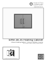
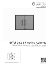
Eiffel 28.35 Floating Cabinet
2 Doors Floating Cabinet / Armoire flottante 2 portes
The indicated values consider static weights and evenly distributed over the parts.
Les valeurs indiquées tiennent compte des poids statiques et uniformément répartis sur les pièces.

n.° ID
2
01
02
03
04
05
2
2
2
1
1
06 1
07 1
04
INCLUDED IN THE PACKAGE / INCLUS DANS LE PACKAGE
Parts identification (Description) / Identification des pièces (Description) Quantity / Quantité
Top Panel and Base / Panneau du haut et Base
Back Panel / Panneau arrière
Side Panel / Panneau latéral
Left Door / Porte gauche
Right Door / Porte droite
REAR VIEW / VUE ARRIÈRE
FRONT VIEW / VUE DE FACE
FINAL APPEARANCE / APPARENCE FINALE
01
02
07
03
03
01
01
02
01
02
03
03
05
06
Shelf / Étagère
Plastic "H" Profile 665mm / Profilé en "H" en plastique 665mm

3
8x
A8x
B8x
C
!IMPORTANT! Two people are recommended to assemble and install this product.
The cabinet must be installed suspended and fixed to the wall (check the conditions of the wall to anchor the cabinet).
IMPORTANT! Deux personnes sont recommandées pour assembler et installer ce produit.
L'armoire doit être installée suspendue et fixée au mur (vérifier les conditions du mur pour ancrer l'armoire).
INCLUDED IN THE HARDWARE / INCLUS DANS LE MATÉRIEL
Simple hammer.
Marteau simple.
Manual screwdriver.
Tournevis manuel.
Electric drill and electric
screwdriver with drill
bit Ø1/2 inch and
phillips tips.
Perceuse électrique
et tournevis électrique
avec foret Ø1/2 pouce
et pointes phillips.
TOOLS NEEDED / OUTILS NÉCESSAIRES
Level indicator.
Indicateur de niveau.
28x
D4x
E4x
F
4x
G40x
H1x
I
1x
J8x
K2x
L
2x
M4x
N4x
O
4x
P

4
02
DETAIL 2 / DÉTAIL 2
0202
01
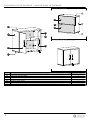
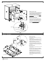
• Connect the Top Panel and Base (01) to
the Side Panels (02) with dowels (A) and
bolts (B).
At the end of the fixing, apply the
adhesive covers (C) on bolts (B).
Connectez les Panneau du haut et Base (01)
sur les Panneaux latéraux (02)des chevilles (A)
et des vis (B).
A la fin de la fixation, appliquez les couvercles
adhésifs (C) sur les vis (B).
Fixing the Back Panels (03):
IMPORTANT! The fixing the Back Panels (03) is optional.
The cabinet can be installed on the wall with or without
the back panels, according to the user's preference.
• Fix the Back Panels (03) by fitting the plastic profile (07) at the
junction between the two parts and applying the nails (D) in
the indicated positions.
STEP 2 / ÉTAPE 2
STEP 3 / ÉTAPE 3
Preparing the Side Panels (02):
• Fix the metal brackets (E) with bolts (H)
in the Side Panels (02), as shown in
the DETAIL 1 and DETAIL 2.
Préparation des Panneaux latéraux (02):
• Fixés les supports métalliques (E) avec
des vis (H) dans le Panneaux latéraux (02),
comme indiqué dans le DÉTAIL 1 et dans
le DÉTAIL 2.
STEP 1 / ÉTAPE 1 DETAIL 1 / DÉTAIL 1
01
02
REAR VIEW / VUE ARRIÈRE
07
03
03
01
02
!
Fixation des Panneaux arrière (03):
IMPORTANT! La fixation des Panneaux arrière (03) est
facultative. L'armoire peut être fixée au mur avec ou sans
les panneaux arrière, selon la préférence de l'utilisateur.
• Fixez le Panneaux arrière (03) en insérant le Profilé en plastique
(07) dans la couture entre les deux pièces et en appliquant les
clous (D) dans les positions indiquées.
!

01
02
DETAIL 3
DÉTAIL 3
Ø1/2 inch hole in the wall
Trou Ø1/2 pouce dans le mur
Kap Toggle bushing (O)
Douille Kap Toggle (O)
Bolt 1/4 x 2.1/4 inch
Vis 1/4 x 2,1/4 pouce
1/2 inch hole in the wall
for bushing and bolt (O).
Trou Ø1/2 pouce dans le
mur pour douille et vis (O).
Installing the cabinet on the wall:
• Place the already assembled cabinet on the desired
site for installation and mark the position for the
holes on the wall to fixation throught the four metal
brackets (E), as shown in the drawing and using
the brackets themselves as a reference.
• With electric drill and drill bit Ø1/2 inch, make the
four holes in the wall and apply the bushings (O).
• Replace the cabinet in the site and apply the bolts
1/4 x 2.1/4 inches as shown in the drawing, for
fixing the brackets (E) at the bushings (O) already
applied on the wall. At the end, apply the plastic
covers (F) over the brackets (E).
Installation du meuble au mur:
• Placez l'armoire déjà assemblée sur le site souhaité
pour l'installation et marquez la position des trous
sur le mur pour la fixation à travers les quatre
supports métalliques (E), comme indiqué sur le
dessin et en utilisant les supports eux-mêmes
comme référence.
• Avec une perceuse électrique et foret Ø1/2 pouce,
faites les quatre trous dans le mur et appliquez les
douilles (O).
• Replacez l'armoire sur le site et appliquez les vis
1/4 x 2,1/4 pouces comme indiqué sur le dessin,
pour la fixation des supports (E) dans les douilles
(O) déjà appliquées sur le mur. À la fin, appliquez
les couvercles en plastique (F) sur les supports (E).
FRONT VIEW / VUE DE FACE
ATTENTION! Before installing the cabinet, check
the conditions of the wall to anchor it and the
existence and posicion of hydraulic, electrical and
gas pipes, avoiding damage to these structures
when drilling the holes for the bushings and bolts.
The Kap Toggle bushings (O) supplied with the product
are for hollow walls or dry wall type. Check the type of
the wall on which the installation will be made and,
if necessary, look for more suitable fixing devices.
To mark the position and fix the cabinet on the
wall, check the level of the entire assembly and
the position of the feet in relation to the floor.
ATTENTION! Avant d'installer l'armoire, vérifiez
les conditions du mur pour l'ancrer ainsi que
l'existence et position des conduites hydrauliques,
électriques et de gaz, en évitant d'endommager
ces structures lors du perçage des trous pour les
douilles et les vis.
Les douilles Kap Toggle (O) fournies avec le produit
sont destinées à des cloisons creuses ou séches.
Vérifiez le type de mur sur lequel l'installation sera
effectuée et, si nécessaire, prévoir des dispositifs de
fixation les plus adaptés.
Pour marquer la position et fixer l'armoire au mur,
vérifiez le niveau de l'ensemble de l'assemblage
et la position des pieds par rapport au étage.
STEP 4 / ÉTAPE 4
5
06
DETAIL 4 / DÉTAIL 4
Preparing the Doors (05) and (06):
• Fix the hinges (G) with bolts (H) in the Doors (05)
and (06), as shown in the DETAIL 4.
• Fix the handle (M) in the Doors (05) and (06)
with bolts (N).
• Fix the metal plate (I) with bolts (K) in the
indicated position on the Left Door (05).
• Fix the lock (J) with bolts (K) in the Right Door (06).
Préparation des Portes (06) et (07):
• Fixez les charnières (G) avec les vis (H) dans les
Portes (05) et (06), comme indiqué dans le DÉTAIL 4.
• Fixez la poignée (M) dans les Portes (05) et (06)
avec des vis (N).
• Fixez la plaque métallique (I) avec les vis (K) dans
la position indiquée sur la Porte gauche (05).
• Fixez la serrure (J) avec les vis (K) dans la Porte
droite (06).
STEP 5 / ÉTAPE 5
05
01
02
01
02

02
Installing the Shelf (04):
• Insert the metal brackets (P) into the holes in the Side Panels (02)
and install the Shelf (04) over them.
• If you prefer, fix the Shelf (04) on the metal brackets (P) applying
the bolts (H), as shown in the DETAIL 5.
Installation de l'Étagère (04):
• Insérez les supports métalliques (P) dans les trous des Panneaux
latéraux (02) et installez l'Étagère (04) par-dessus.
• Si vous préférez, fixez l'Étagère (04) sur les supports métaliques (P)
en appliquant les vis (H), comme indiqué dans le DÉTAIL 5.
STEP 7 / ÉTAPE 7
STEP 6 / ÉTAPE 6
6
DETAIL 5 / DÉTAIL 5
02
04
01
01
02
04
Fixer and adjustment bolts.
Vis de fixation et réglage.
Installing the Doors (05) and (06):
• Fix the hinges connectors (G) of the Doors (05)
and (06) on the Side Panels (02) with bolts (H),
taking the markings in these Panels (02) as a
reference for correct positioning.
The hinge and its connector includes two more
bolts, shown in DETAIL 6. Use these fixer and
adjustment bolts to tighten, adjust and align
the doors.
• Fix the metal stopper (L) on the Base (01) with
bolts (K) so that both doors are aligned.
Installation des Portes (05) et (06):
• Fixez les connecteurs des charnières (G) des
Portes (05) et (06) sur les Panneaux latéraux
(02) avec des vis (H), en prenant les marques
comme référence pour un positionnement correct.
La charnière et son connecteur comprennent
deux autres vis, illustrées dans le DÉTAIL 6.
Utilisez ces vis de fixation et réglage pour serrer,
régler et aligner les portes.
• Fixez la butée métallique (L) à na Base (01)
avec des vis (K) afin que les deux portes
soient alignées.
DETAIL 6 / DÉTAIL 6
02
05
06
01
04
02

Ed. 001, 2022/06 - Manhattan Comfort.
888-230-2225
help@manhattancomfort.com
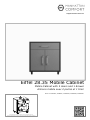
Model # 252BMC6, 252BMC8, 252BMC83, 252BMC84, 252BMC85
26
lb
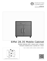
Eiffel 28.35 Mobile Cabinet
Mobile Cabinet with 2 doors and 1 drawer
Armoire mobile avec 2 portes et 1 tiroir
The indicated values consider static weights and evenly distributed over the parts.
Les valeurs indiquées tiennent compte des poids statiques et uniformément répartis sur les pièces.
15
lb
20
lb
15
lb

n.° ID
2
01
02
03
04
05
1
1
1
06 2
07 1
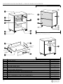
INCLUDED IN THE PACKAGE / INCLUS DANS LE PACKAGE
Parts identification (Description) / Identification des pièces (Description) Quantity / Quantité
Left Side Panel / Panneau latéral gauche
Door / Porte
REAR VIEW / VUE ARRIÈRE
FRONT VIEW - FINAL APPEARANCE
VUE DE FACE - APPARENCE FINALE
05
02
14
01
10
12
03
Base / Base
Back Panel / Panneau arrière
1
1
Removable Shelf / Étagère amovible
08 2
Crossbar / Traverse
Plastic "H" Profile 667mm / Profilé en "H" en plastique 667mm
1
Right Side Panel / Panneau latéral droit
Top Panel / Panneau du haut
1
1
1
1
Front of the drawer / Devant du tiroir
Left Side Panel of the drawer / Panneau latéral gauche du tiroir
Rear Panel of the drawer / Panneau arrière du tiroir
Base of the drawer / Base du tiroir
1
Right Side Panel of the drawer / Panneau latéral droit du tiroir
09
10
11
12
13
1
14
15
2
16
Metallic slide
Glissière
métallique
Caster RIS 50 PL ZB, without lock / Roulettes RIS 50 PL, pas de blocage
2
Caster RIS 50 PL TR, with lock / Roulettes RIS 50 PL, avec blocage
02
04
05
06
06
07
08
09
11
13
06
06
04
Metallic slide
Glissière métallique
Metallic slide
Glissière
métallique
16
15
15
16 15
16

3
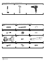
18x
A8x
B4x
C
INCLUDED IN THE HARDWARE / INCLUS DANS LE MATÉRIEL
TOOLS NEEDED / OUTILS NÉCESSAIRES
6x
D6x
E38x
F
4x
G28x
H3x
I
6x
J4x
K16x
L
Simple hammer.
Marteau simple.
Manual screwdriver.
Tournevis manuel.
Electric screwdriver with phillips tips.
Tournevis électrique avec pointes phillips.

4
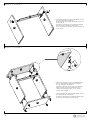
STEP 2 / ÉTAPE 2
STEP 1 / ÉTAPE 1
DETAIL 1 / DÉTAIL 1
!
• Connect the Crossbar (01) to the Side Panels (02) and
(03) with dowels (A) and bolts (B).
At the end of the fixing, apply the adhesive covers (C)
on the bolts (B).
Connectez le Traverse (01) sur les Panneaux latéraux
(02) et (03) des chevilles (A) et des vis (B).
A la fin de la fixation, appliquez couvercles adhésifs (C)
sur les vis (B).
01
03
04
05
01
02
02
03
05
03
• Connect the Top Panel (05) over the Side Panels (02)
and (03) with dowels (A) and cam lock hardware
(D + E), as shown in the DETAIL 1.
Connectez le Panneau du haut (05) sur les Panneaux
latéraux (02) et (03) avec les chevilles (A) et du
matériel de verrouillage à came (D + E), comme
indiquée dans le DÉTAIL 1.
• Connect the Base (04) under the Side Panels (02) and
(03) with dowels (A) and bolts (B).
Connectez la Base (04) sur les Panneaux latéraux (02)
et (03) avec des chevilles (A) et des vis (B).

STEP 4 / ÉTAPE 4
STEP 3 / ÉTAPE 3
!
5
Fixing the Back Panels (06):
• Fix the Back Panels (06) by fitting the plastic profile
(14) at the junction between the two parts and
applying the nails (F) in the indicated positions.
Fixation des Panneaux arrière (06):
• Fixez les Panneaux arrière (06) en insérant le Profilé
en plastique (14) dans la couture entre les deux
pièces et en appliquant les clous (F) dans les
positions indiquées.
03
04
05
01
02
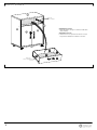
Fixing the casters (15) and (16):
• Fix the casters (15) and (16) under the Base (04)
with the bolts (L), in the positions shown in drawing.
Apply four bolts (L) to each caster .
Fixation des roulettes (15) et (16):
• Fixez les roulettes (15) et (16) sous la Base (04) avec
les vis (L), dans les positions indiquées sur le dessin.
Appliquer quatre vis (L) sur chaque roulette.
15
16
15
16
14
16
16
15
06
04
02
05
06

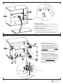
Installing the Shelf (07):
• Insert the metal brackets (K) into the holes in the Panels (02)
and (03) and install the Shelf (07) over them.
• If you prefer, fix the Shelf (07) on the metal brackets (K)
applying the bolts (H), as shown in the DETAIL 2.
Installation de Étagère (07):
• Insérez supports métalliques (K) dans les trous des Panneaux
latéraux (02) et (03) et installez l'Étagère (07) dessus.
• Si vous préférez, fixez l'Étagère (07) sur les supports
métaliques (K) en appliquant les vis (H), comme indiqué dans
le DÉTAIL 2.
STEP 6 / ÉTAPE 6
STEP 5 / ÉTAPE 5
!
04
02
6
DETAIL 2 / DÉTAIL 2
DETAIL 3 / DÉTAIL 3
03
05
07
03
07
Preparing the Doors (08):
• Fix the hinges (G) with bolts (H) in the Doors (08), as shown
in the DETAIL 3.
• Fix the handles (I) with bolts (J) in the Doors (08).
Préparation des Portes (08):
• Fixez les charnières (G) avec les vis (H) dans les Portes (08),
comme indiqué dans le DÉTAIL 3.
• Fixez la poignée (I) dans les Portes (08) avec des vis (J).
08 08

STEP 8 / ÉTAPE 8
STEP 7 / ÉTAPE 7
Fixer and adjustment bolts.
Vis de fixation et réglage.
Installing the Doors (08):
• Fix the hinges connectors (G) of the Doors (08)
on the Side Panels (02) and (03) with bolts (H),
taking the markings in these Panels (02) and
(03) as a reference for correct positioning.
The hinge and its connector includes two more
bolts, shown in DETAIL 4. Use these fixer and
adjustment bolts to tighten, adjust and align
the doors.
Installation des Portes (08):
• Fixez les connecteurs des charnières (G) des
Portes (08) sur les Panneaux latéraux (02) et
(03) avec des vis (H), en prenant les marques
comme référence pour positionnement correct.
La charnière et son connecteur comprennent
deux autres vis, illustrées dans le DÉTAIL 4.
Utilisez ces vis de fixation et réglage pour
serrer, régler et aligner les portes.
09
DETAIL 4
DÉTAIL 4
02
05
03
08
08
07
04
Preparing the drawer:
• Fix the handle (I) with bolts (J) in the Front of
the drawer (09).
• Connect the parts (09), (10), and (11) with the
dowels (A) and cam lock hardware (D + E), as
shown in DETAIL 5. Apply adhesive covers (C).
• Connect the parts (10), (11) and (12) with the
dowels (A) and bolts 5,0 x 50mm (B).
• Insert the Base of the drawer (13) into the
channel in the Side Panels (10) and (11) and
in the Front of the drawer (09), and fix it at the
lower edge of the Rear Panel of the drawer (12)
with nails (F).
Préparation du tiroir:
• Fixez la poignée (I) dans le Devant du tiroir (09)
avec des vis (J).
• Connectez les pièces (09), (10) et (12) avec
les chevilles (A) et le matériel de verrouillage à
came (D+E), comme indiqué dans le DÉTAIL 5.
Appliquez les couvercles adhésifs (C).
• Connectez les pièces (10), (11) et (12) avec
les chevilles (A) et des vis 5,0 x 50mm (B).
• Insérer la Base du tiroir (13) dans le canal des
Panneaux latéraux (10) et (11) et dans la
Devant du tiroir (09) et le fixer au du bord
inférieur du Panneau arrière du tiroir (12) avec
des clous (F).
Metallic slide
Glissière métallique
10
11
12
13
09
10
7
DETAIL 5
DÉTAIL 5

STEP 9 / ÉTAPE 9
!
02
8
03
09
Installing the drawer:
• Install the drawer, fitting it so that the metal slides
slide smoothly.
Installation du tiroir:
• Installez le tiroir en l'ajustant de manière à ce que
les glissières métalliques coulissent en douceur.
10
11
12
13
Metallic slide
Glissière métallique
Metallic slide
Glissière métallique
05
01
08
08
04
-
 1
1
-
 2
2
-
 3
3
-
 4
4
-
 5
5
-
 6
6
-
 7
7
-
 8
8
-
 9
9
-
 10
10
-
 11
11
-
 12
12
-
 13
13
-
 14
14
-
 15
15
-
 16
16
-
 17
17
-
 18
18
-
 19
19
-
 20
20


Manhattan Comfort Eiffel 3-Piece Garage Set Assembly Manual
- Taper
- Assembly Manual
dans d''autres langues
Documents connexes
Autres documents
-
ROOMS TO GO 21023318 Assembly Instructions
-
-
GE ZKFN Guide d'installation
-
-
GE ZIC360NHRH Guide d'installation
-
Bosch Benchmark B30IB800SP Guide d'installation
-
Thermador T36IT800NP Guide d'installation
-
Ameriwood Home HD45101 Mode d'emploi