ROOMS TO GO 21023445 Assembly Instructions
- Taper
- Assembly Instructions

888-230-2225
help@manhattancomfort.com
Ed. 002, 2020/10 - Manhattan Comfort.
Model # 234BMC12, 234BMC6, 234BMC82, 234BMC9
33
lb
14
lb
14
lb
14
lb
11
lb
11
lb
11
lb
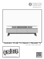
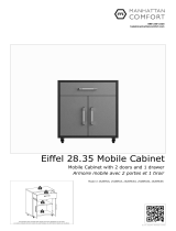
Yonkers 70.86 TV Stand / Meuble TV
The indicated values consider static weights and evenly distributed over the parts.
Les valeurs indiquées tiennent compte des poids statiques et uniformément répartis sur les pièces.

2
07
04
01
02
03
05
06
08
09
12
12
10
04
12
13
14
08
08
08
11
13
13
13
11
10
08
08
13
14
03
01
09
13
13
13
01
04
06
07
08
02
05
03
09
10
11
12
13
14
1
1
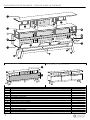
Front Frame / Cadre avant
Partition / Cloison 2
3
Lower Back Panel / Panneau arrière inférieur
1
Left Side Panel / Panneau latéral gauche
1
Base / Base
Upper Support / Support superieur 4
Top Panel / Panneau du haut 1
1
1
4
Wood Feet / Pieds en bois
1
Front Bar / Barre avant
1
Right Side Panel / Panneau latéral droit
Upper Back Panel / Panneau arrière supérieur
Tilting Door / Porte basculante
2
Structural Bar for feet / Barre structurelle de pieds
n.° ID
REAR VIEW / VUE ARRIÈRE FRONT VIEW / VUE DE FACE
FINAL APPEARANCE / APPARENCE FINALE
INCLUDED IN THE PACKAGE / INCLUS DANS LE PACKAGE
Quantity / Quantité
Parts Identification (Description) / Identification des pièces (description)
Middle Shelf / Étagère du milieu

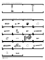
A28x
3
B20x C20x D10x (main color)
E5x F8x G34x H8x
I6x J52x K6x L24x
M4x N6x O4x (feet color) P8x
Q4x R4x
INCLUDED IN THE HARDWARE / INCLUS DANS LE MATÉRIEL
TOOLS NEEDED / OUTILS NÉCESSAIRES

4
14
13
07
14
13
13
13
13
14
03
02
01
04
07
04
13
14
13
13
06
05
13
13
14
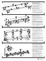
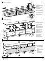
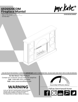
Preparing the Feet (13) with
the Structural Bars (14):
• Fix the Feet (13) in the Structural Bars
(14) with dowels (A) and bolts (P).
• Fix the brackets (N) with bolts (G) in
the Structural Bars (14).
• Apply the covers (O) and the protective
felts (R) in the Feet (13).
Préparation des Pieds (13) avec les
Barres structureles (14):
• Fixez les Pieds (13) aux Barres
structuralles (14) avec des chevilles (A)
et des vis (P).
• Fixez les supports métalliques (N) avec
des vis (G) sur Barres structuralles (14).
• Appliquez les couvercles (O) et feutres
de protection (R) sur les Pieds (13)
Fixing the Base (07) on Feet (13) and
on the Structural Bars (14):
• Fix the Base (07) on the Feet (13) with
bolts (P), as shown in the drawing.
• Apply the plastic cover (Q) on bolts (P).
• Fix the Structural Bars (14) in the Base
(07) applying bolts (G) in the metal
brackets (N).
Fixation de la Base (07) sur les Pieds
(13) et les Barres structurelles (14):
• Fixez la Base (07) aux Pieds (13) avec
des vis (P), comme indiqué sur le dessin.
• Appliquez couvercles (Q) sur les vis (P).
• Fixez les Barres structurelles (14) sous
la Base (07) en appliquant les vis (G) sur
les supports métalliques (N).
• Connect the Left Side Panel (02) and the
Right Side Panel (03) under the Middle
Shelf (01) with dowels Ø6x30mm (A)
and cam lock hardware (B + C).
Connectez les Panneaux latéraux (02) et
(03) sous l'Étagère du milieu (01) avec
des chevilles Ø6x30mm (A) et le matériel
de verrouillage à came (B + C).
• Connect the Partitions (04) under the
Middle Shelf (01) with dowels Ø6x50mm
(M) and bolts (H).
Connectez les Cloisons (04) sous la
Étagère du milieu (01) avec des chevilles
Ø6 x 50mm (M) et des vis (H).
• Connect the Base (07) under the Left Side
Panel (02), the Right Side Panel (03) and
the Partitions (04) with dowels Ø6x30mm
(A) and bolts 5.0 x 50mm (H).
Connectez la Base (07) sous les Panneaux
latéraux (02) et (03) et les Cloisons (04)
avec des chevilles Ø6 x 30mm (A) et des
vis 5.0 x 50mm (H).
Preparing the Frame (05) with Bar (06):
• Fix the Front Frame (05) on the Front Bar
(06), positioning them according to the
drawing and applying the bolts (E).
• Fix six metal brackets (F) with bolts (G)
on the inner face and near the top edge of
the Frame (05), as shown in the drawing.
• Fix the metal brackets (F) with bolts (G)
on the lower face and near the ends of the
Front Bar (06), as shown in the drawing.
Préparation du Cadre avant (05) avec
la Barre avant (06):
• Fixez le Cadre avant (05) sur la Barre
avant (06), en le positionnant selon le
dessin et en appliquant les vis (E).
• Fixez les six supports métalliques (F)
avec des vis (G) sur la face intérieure et
prés du bord supérieur du Cadre (05),
comme indiqué sur le dessin.
• Fixez les supports métalliques (F) avec
des vis (G) sur la face inférieure et prés
des extrémités de la Barre avant (06).
STEP 1 / ÉTAPE 1
STEP 2 / ÉTAPE 2
STEP 3 / ÉTAPE 3
STEP 4 / ÉTAPE 4
DETAIL 1
DÉTAIL 1
Inner face.
Face intérieure.
Lower face.
Face inférieure.
13
13

5
02
04
01
06 05
03 07
13
14
02
06
05
01
14
04
13
09
08
08
08
08
01
02
04
07
04
03
13
13
13
13
14
08
08
07
11
03
01
09 Rear
edge.
13
13
13
13
14
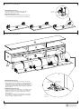
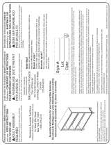
• Fix the Front Frame (05)
under the Middle Shelf (01)
with the metal brackets (F)
and bolts (G).
Fixez le Cadre avant (05)
sous l'Étagère du milieu (01)
avec les supports
métalliques (F) et les vis (G).
• Fix the ends of the Front Bar
(06) in the Side Panels (02)
and (03) with the metal
brackets (F) and bolts (G).
Fixez les extrémites de la
Barre avant (06) aux
Panneaux latéraux (02) et
(03) avec les supports
métalliques (F) et les vis (G).
DETAIL 2
DÉTAIL 2
• Fix the Upper Supports (08)
on the Middle Shelf (01)
with dowels (A) and (M),
as shown in the drawing,
and with cam lock hardware
(B + C).
Fixez Supports supérieurs
(08) sur l'Étagère du milieu
(01) avec les chevilles (A)
et (M), comme indiqué sur
le dessin, et avec le
matériel de verrouillage
à came (B + C).
• Fix the Top Panel (09) on
the Upper Supports (08)
with dowels (A) and
cam lock hardware (B + C).
Fixez le Panneau du haut
(09) sur les Supports
supérieurs (08) avec des
chevilles (A) et le
matériel de verrouillage
à came (B + C).
• Fix the Back Panels (10)
and (11) with nails (J).
At the junction between
the two back panels,
use also the metallic
plates (I).
Fixez les Panneaux arrière
(10) et (11) avec des
clous (J).
A la jonction entre les
deux panneaux arrière,
utilisez également les
plaques métalliques (I).
STEP 5 / ÉTAPE 5
STEP 6 / ÉTAPE 6
STEP 7 / ÉTAPE 7
Rear edge.
Bord arrière.
Lower face.
Face inférieure
Rear edge.
Bord arrière.
Rear edge.
Bord arrière.
10
13

6
07
01
02
03
04
08
12
08
09
04
12
12
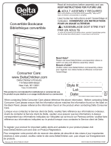
DETAIL 3
DÉTAIL 3
Preparing the Doors (12):
• Fix the hinges (K) on the three Doors (12) with
bolts 4.0 x 14mm (L), as shown in DETAIL 3.
Préparation des Portes (12):
• Fixez les charnières (K) aux trois Portes (12) avec les
vis 4.0 x 14mm (L), comme indiqué dans le DÉTAIL 3.
12 Inner face.
Face intérieure.
Installing the Doors (12):
• Fix the hinge connectors (K) of the Doors (12) on the
Base (07) with bolts 4.0 x 14mm (L), taking the markings
on the Base (07) as a reference for correct positioning.
The hinge connector includes two bolts, shown in DETAIL 4.
Use the fixer and adjustment bolts to tighten, adjust and
align the doors.
Installation des Portes (12):
• Fixez les connecteurs des charnières (K) des Portes (12) sur
la Base (07) avec des vis 4.0 x 14mm (L), en prenant les
marques sur la Base (07) comme référence pour correct
positionnement.
Le connecteur de charnière comprend deux vis, illustrées
dans le DÉTAIL 4. Utilisez les vis de fixation et de réglage
pour fixer, régler et aligner les portes.
Adjustment bolt
Vis de réglage
Fixer bolt
Vis de fixation
DETAIL 4
DÉTAIL 4
STEP 8 / ÉTAPE 8
STEP 9 / ÉTAPE 9
12 Inner face.
Face intérieure. 12 Inner face.
Face intérieure.
-
 1
1
-
 2
2
-
 3
3
-
 4
4
-
 5
5
-
 6
6


ROOMS TO GO 21023445 Assembly Instructions
- Taper
- Assembly Instructions
dans d''autres langues
- English: ROOMS TO GO 21023445
Documents connexes
Autres documents
-
 Manhattan Comfort Eiffel 6-Piece Garage Set Assembly Manual
-
 Manhattan Comfort Eiffel 5-Piece Garage Set Assembly Manual
-
 Manhattan Comfort Eiffel 3-Piece Garage Set Assembly Manual
-
 Manhattan Comfort Eiffel Garage Work Station Set of 3 Assembly Manual
-
 Dorel Home 6926920COM Assembly Manual
-
 Delta Children Monterey Bookcase/Hutch Assembly Instructions
-
 Delta Children Chalet Bookcase/Hutch Assembly Instructions
-
Delta Children Epic Bookcase/Hutch Assembly Instructions
-
 Delta Children Bennington Elite Bookcase/Hutch Assembly Instructions
-
Costway CB10372CF Manuel utilisateur


