
GE is a trademark of the General Electric Company. Manufactured under trademark license.
OWNER’S MANUAL
AIR CONDITIONER
RV
49-5000406 Rev. 3 12-20 GEA
SAFETY INFORMATION .........3
INSTALLATION INSTRUCTIONS
Before You Begin ......................4
Tools You will Need ....................4
RARMN_ _ Parts List ...................5
RAREN_ _ Parts List ...................6
RARED_ _ Parts List ...................7
Roof Requirements ....................8
Roof Requirements and Prep ............9
Electrical Requirements ................9
Placing Unit on Roof ...................9
Installing Unit ........................10
Electrical Control Installation ........... 11
USING THE AIR CONDITIONER
Controls .............................12
Air Direction .........................13
Normal Operating Sounds .............13
CARE AND CLEANING
Indoor Panel .........................14
Air Filter .............................14
Annual Maintenance ...................14
TROUBLESHOOTING ............15
SCHEMATIC DIAGRAMS ........16
LIMITED WARRANTY ...........17
CONSUMER SUPPORT ..........18
Rooftop Units:
ARC13AAC_
ARC15AAC_
ARC13AHC_
ARH15AAC_
Indoor Assemblies
RARMN_ _
RAREN_ _
RARED_ _
ENGLISH
Write the model and serial numbers
here:
Model # _______________
Serial # _______________
You can find them on a label on the
air conditioner.

2 49-5000406 Rev. 3
THANK YOU FOR MAKING GE APPLIANCES A PART OF YOUR RV
Whether you grew up with GE Appliances, or this is your first, we’re happy to have you in the family.
We take pride in the craftsmanship, innovation and design that goes into every GE Appliances
product, and we think you will too. Among other things, registration of your appliance ensures that we
can deliver important product information and warranty details when you need them.
Register your GE appliance now online. Helpful websites and phone numbers are available in the
Consumer Support section of this Owner’s Manual.

49-5000406 Rev. 3 3
SAFETY INFORMATION
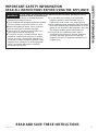
IMPORTANT SAFETY INFORMATION
READ ALL INSTRUCTIONS BEFORE USING THE APPLIANCE
For your safety, the information in this manual must be followed to minimize the risk of
fire, electric shock or personal injury.
Ŷ8VHWKLVDSSOLDQFHRQO\IRULWVLQWHQGHGSXUSRVHDV
described in this Owner’s Manual.
ŶThis air conditioner must be properly installed in accordance
with the Installation Instructions before it is used.
ŶReplace immediately all electric service cords that
have become frayed or otherwise damaged.
ŶTurn the unit OFF and disconnect all power to the
vehicle before cleaning and servicing.
ŶTo avoid risk of injury or property damage, the air
conditioner should only be serviced by a qualified
servicer who holds a current valid certificate from
an industry-accredited assessment authority, which
authorizes their competence to handle refrigerants
safely in accordance with industry recognized
assessment specifications.
ŶFor your safety, do not store or use combustible
materials, gasoline or other flammable vapors or
liquids in the vicinity of this or any other appliance.
ŶAll air conditioners contain refrigerants, which under federal
law must be removed prior to product disposal. If you are
getting rid of an old product with refrigerants, check with
the company handling disposal about what to do.
ŶThese R410A air conditioning systems require
contractors and technicians to use tools, equipment
and safety standards approved for use with this
refrigerant. DO NOT use equipment certified for R22
refrigerant only.
WARNING
READ AND SAVE THESE INSTRUCTIONS

4 49-5000406 Rev. 3
Installation Instructions
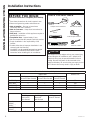
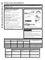
BEFORE YOU BEGIN
Read these instructions completely and carefully.
•
Save these instructions for local inspector’s use.
•
Observe all governing codes and ordinances.
• Note to Installer – Be sure to leave these
instructions with the Consumer.
• Note to Consumer – Keep these instructions for
future reference.
• Skill level – Installation of this appliance requires a
qualified RV technician.
• Completion time – Approximately 1 hour
• We recommend that two people install this product.
• Proper installation is the responsibility of the
installer.
• Product failure due to improper installation is not
covered under the Warranty.
<RX0867XVHDOOVXSSOLHGSDUWVDQGXVHSURSHU
installation procedures as described in these
instructions when installing this air conditioner.
Questions? Call 1-877-540-7837 or Visit our Website at: GEAppliances.com
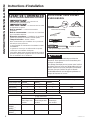
TOOLS YOU WILL NEED
Phillips head screwdriver
Ruler or tape measure
Pencil
Level
Scissors or knife
Torque Wrench (0-60 in-lbs)
Drill and 1/8” drill bit
CAUTION
Be cautious of sharp edges as they may cause injury.
When lifting the air conditioner, use 2 people to lift.
Electrical wiring may be present between roof and
ceiling. Be sure that power is disconnected at the
mains and battery. Be sure that the gas supply is shut
off. Failure to do so may result in injury or death.
INSTALLATION INSTRUCTIONS
,QGRRU8QLWV
RARMN_ _
Mechanical
Non-Ducted
RAREN_ _
Electronic
Non-Ducted
RARED_ _
Electronic Ducted
Elec. Control
RARMC_ _
RAREC_ _
99
Wall Thermostat
RARWT_ _
99
Table #1 - Model Compatibility List
,QGRRU8QLWV Breaker Size
2XWGRRU8QLWV RARMN_ _
Mechanical Non-Ducted
RAREN_ _
Electronic Non-Ducted
RARED_ _
Electronic Ducted
ARC13AHC_
999
15A
ARC13AAC_
999
20A
ARC15AAC_
999
20A
ARH15AAC_
99
20A

49-5000406 Rev. 3 5
INSTALLATION INSTRUCTIONS
Installation Instructions
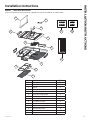
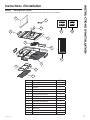
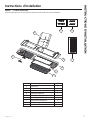
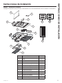
RARMN_ _- Mechanical Non-Ducted
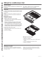
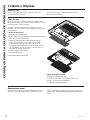
Check the contents of the accessories supplied with your air conditioner as shown below:
Number Part Name QTY.
1 Filter Retainer 1
2 Filter 1
3 Knobs 2
4 Ceiling Panel 1
5 Side Discharge Ports 4
6 Direct Discharge Guide 1
7 Mounting template 1
8 Junction Box Cover 1
9 Connection Shield 1
10 Air division baffle 1
11 Baffle retainer plates 2
12 M8 Mounting Bolts 4
13 Wood screws 8
14 Sheet metal screws 6
1
2
3
4
5
6
7
8
9
10
12
13
11
14

6 49-5000406 Rev. 3
Installation Instructions
INSTALLATION INSTRUCTIONS
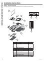
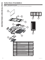
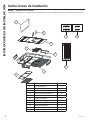
Number Part Name QTY.
1 Filter Retainer 1
2 Filter 1
3 Ceiling Panel 1
4 Side Discharge Ports 4
5 Direct Discharge Guide 1
6 Mounting template 1
7 Air division baffle 1
8 M8 Mounting Bolts 4
9 Wood screws 8
10 Baffle retainer plates 2
11 Sheet metal screws 6
1
2
3
4
5
6
7
8
9
10
11
RAREN_ _- Electronic Non-Ducted
Check the contents of the accessories supplied with your air conditioner as shown below:

49-5000406 Rev. 3 7
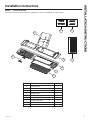
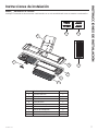
Number Part Name QTY.
1 Filter Retainer 1
2 Filter 1
3 Screw Cover (left and right) 2
4 Ceiling Panel 1
5 Mounting template 1
6 Air division baffle 1
7 M8 Mounting Bolts 4
8 Wood Screws 8
9 Sheet metal screws 9
1
2
3
4
5
6
7
8
9
RARED_ _- Electronic Ducted
Check the contents of the accessories supplied with your air conditioner as shown below:
Installation Instructions
INSTALLATION INSTRUCTIONS

8 49-5000406 Rev. 3
INSTALLATION INSTRUCTIONS
Installation Instructions
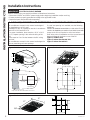
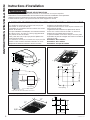
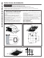
A. ROOF REQUIREMENTS AND DETERMINING LOCATION FOR INSTALLATION
Air conditioners covered in this manual are designed
for installation on an RV’s roof.
Installation of this air conditioner must be in accordance
with NFPA 1192 and NFPA 70.
For proper installation, there must be a 14 ñ»” x 14 ñ»”
(+/-ï»”) square opening in the roof and ceiling of the
RV.
There must be 2 to 6 inches between the RV ceiling
and roof.
Air conditioners covered in this manual are designed to
fit over preexisting roof vent openings.
If a roof vent opening isn’t available, use the following
guidelines:
8QLWLVWREHLQVWDOOHGFHQWHUHGVLGHWRVLGHRQWKH59URRI
8QLWLVWREHLQVWDOOHGRQDVHFWLRQRIURRIZKLFKLVOHYHOZLWK
respect to the RV roof if parked on a flat, level surface
.
Roof at the point of installation can have a maximum 15
degree tilt towards the front or rear of the RV.
Figure 1: Outdoor Unit
Figure 2: Indoor Non-Ducted Unit
Figure 3: Indoor Ducted Unit
Figure 1: Outdoor unit:
32 - 7/8”
27 - 3/4”
13 - 7/8”
Figure 2: Indoor Non-Ducted Unit:
23”
21”
2 -1/2”
14 - 1/4”
3 - 1/2”
14
-
1/4”
6 - 1/2”
2 - 1/2”
Roof opening
18”
Center Line of unit
Keep at least 18” free of obstructions at rear of unit.
Roof opening
Front
13 - 7/8”
4 - 7/8”
WARNING
ELECTRICAL SHOCK HAZARD
Death or serious injury can result from failure to follow these instructions.
• Disconnect 115VAC and 12VDC power supply before beginning installation and/or servicing
• Ensure product is properly grounded according to the applicable codes
• Replace all parts and panels before operating
Figure 3: Indoor Ducted Unit:
17”
17”
5/8”
Roof Opening
14 - 1/4”
14 - 1/4”
1 - 3/8”
1 - 3/8”

49-5000406 Rev. 3 9
Installation Instructions
C. ELECTRICAL REQUIREMENTS
These models require a 115-volt, 60-Hz protected with
either a 15-amp or 20-amp time-delay fuse or circuit
breaker (see table 1 on page 4).
8VHDPLQLPXPRIVKHDWKHG$:*FRSSHUZLUH
with ground.
Be sure that 16” of supply wire is passed through the
framing. This ensures enough wire is available for an
easy connection in the junction box.
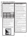
B. ROOF REQUIREMENTS AND
PREPARATION
If a preexisting roof vent opening will be used:
8QVFUHZDQGUHPRYHURRIYHQWIURP59
2. Seal all holes and seams with a weather resistant
sealant.
3. Measure the width and length of the vent opening.
If the opening doesn’t comply with the requirements
from section A, it must be resized.
If a preexisting opening will not be used, a new opening
will be cut through both the roof and ceiling of the RV.
7KLVRSHQLQJ0867EHEHWZHHQVWUXFWXUDOURRI
members.
2. Do NOT cut structural roof members to create
opening for this air conditioner. Doing so may
cause damage to RV and air conditioner.
3. Do NOT create a low spot on the RV roof. Water
can pool and may leak through the opening.
The square opening must be boxed with framing
at least 3/4” thick to withstand the load from the
compression bolts.
Be sure to provide an access hole for RV wiring
toward the front of the 14 ñ»” x 14 ñ»” opening.
Roof and RV structure at point of install must be
strong enough to support air conditioner without
any deflection. If in doubt, please contact your RV
manufacturer. Deflection will allow water to pool at the
air conditioner’s gasket, and may cause a leak.
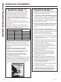
D. PLACING UNIT ON ROOF
CAUTION
LIFTING HAZARD. Ensure proper
lifting methods and controls are
used when lifting unit to the RV roof. Failure to do so
can result in injury.
1. Remove unit from packaging and dispose of
packaging.
2. Do not slide the unit on its mounting gasket.
'DPDJHWRJDVNHWFDQFDXVHDOHDN8VLQJWZR
people, lift the unit and place it over the prepared
opening. The front of the unit must face the RV’s
direction of travel. Damage to condenser fan and
coil will occur if this instruction is not followed.
WARNING
It is important that these installation
instructions are read and understood before
installation and use.
Failure to securely install the unit to the RV before
moving the RV may result in personal injury or death.
Do not operate the unit or recreational vehicle until the
unit is fully secured on roof.
3. Bring the ceiling assembly with all provided
mounting hardware into the RV. All work on the
exterior of the RV is now complete.
INSTALLATION INSTRUCTIONS

10 49-5000406 Rev. 3
E. MECHANICAL NON-DUCTED
INSTALLATION (RARMN_ _)
1. From inside the RV, double check the gasket’s
position and alignment above the roof opening.
Adjust if necessary. The air conditioner can be
moved and adjusted by pushing upwards from
inside the RV.
2. Reach through the base pan and pull the electrical
power cord from the air conditioner through the
ceiling opening.
3. Measure ceiling to roof thickness.
4. Cut rows from the bottom of the foam baffle
according to the table below:
Ceiling to roof thickness (in) Rows to cut
Minimum Maximum
22.510
2.5 3 8
3.5 4 6
4.5 5 4
55.52
5.5 6 0
Best Practice:
Cut away one row at a time and check installation
position of baffle. With the top foam compressed
onto the air conditioner’s base pan, the bottom of the
baffle should be flush to the ceiling opening.
5. Install 2 baffle retainer plates onto the ceiling
assembly (Optional).
6. Place foam baffle into position between 2 retainer
plates.
7. Push the mounting template into the roof opening,
and begin hand-threading each of the 4 mounting
bolts through the nuts in the base pan.
8. Tighten the 4 bolts evenly to 35 ± 5 inch pounds
using a torque wrench at least rated for 0-60 in-lbs.
Even compression is required to prevent leaks
through the gasket.
9. Remove 6 pin connection cover from the ceiling
assembly.
E. MECHANICAL CONTROL
INSTALLATION
(cont.)
10. Plug 6 pin connector from the roof mounted air
conditioner into the electronic control box.
11. Reassemble the 6 pin connection cover to the
ceiling assembly.
12. Remove junction box cover.
13. Route the 115 VAC power cord through the strain
relief of the ceiling assembly. Tighten the strain
relief, making sure not to damage the wires.
8VLQJZLUHFRQQHFWRUVFRQQHFWOLQHWREODFN
neutral to white, and ground to green.
8VLQJHOHFWULFDOWDSHVHFXUHWKHFRQQHFWRUWR
prevent any potential movement due to vehicle
vibration.
16. Push wires and connections into the junction box.
Reinstall junction box cover.
17. Align plastic ceiling panel to the metal assembly.
18. Install the 2 control knobs.
19. Install the 2 provided sheet metal screws to attach
the plastic panel to the metal assembly. The filter
must be removed to install these screws.
20. Apply pressure to the center of the plastic panel,
drive the 2 wood screws at the location shown in
the figure below. The air discharge doors should
be partially open; otherwise, these screws will be
difficult to drive.
21. Drive the remaining 6 wood screws. The air
discharge doors should be hinged partially open;
otherwise, these screws will be difficult to drive.
22. Assemble the filter to the plastic panel.
23. Installation is complete. Refer to “Controls” on
page 12 before attempting to operate the air
conditioner.
Installation Instructions
INSTALLATION INSTRUCTIONS

49-5000406 Rev. 3 11
INSTALLATION INSTRUCTIONS
Installation Instructions
F. ELECTRONIC DUCTED
(RARED_ _) INSTALLATION
1. From inside the RV, double check the gasket’s
position and alignment above the roof opening.
Adjust if necessary. The air conditioner can be
moved and adjusted by pushing upwards from
inside the RV.
2. Reach through the base pan and pull the electrical
power cord from the air conditioner through the
ceiling opening.
3. Push the ceiling mounting template into the roof
opening and begin hand-threading each of the 4
mounting bolts through the nuts in the base pan.
4. Tighten the 4 bolts evenly to 35 ± 5 inch pounds
using a torque wrench at least rated for 0-60
in-lbs. Even compression is required to prevent
leaks through the gasket.
5. Place dividing baffle into position on the ceiling
assembly. Ensure baffle is pressed against the
base pan, forming an airtight seal.
6. Mount the dividing baffle to the mounting template
using three screws.
7. Mount the dividing baffle to the framing timber
using two screws on each side, creating an airtight
seal.
8. Mount the Main Control Box (RARMC_ _) to the
mounting template using four screws.
9. Remove three screws from main control box,
allowing the bottom section to hinge open. Control
board is now visible and accessible.
10. Route the 115 VAC power cord through the strain
relief of the control box. Tighten the strain relief,
making sure not to damage the wires.
8VLQJZLUHFRQQHFWRUVFRQQHFWOLQHWREODFN
neutral to white, and ground to green.
8VLQJHOHFWULFDOWDSHVHFXUHWKHFRQQHFWRUVWR
prevent any potential movement due to vehicle
vibration.
5RXWHWKHSLQFRQQHFWRUWKURXJKWKH86KDSHG
opening of the control box. Mate 6 pin connector
to the control box’s wire harness.
8VLQJZLUHFRQQHFWRUVFRQQHFWIXUQDFHZLUHV
(blue), 3 thermostat wires (red, yellow, black), and
two 12 VDC battery wires (red and black).
F. ELECTRONIC DUCTED
(RARED_ _) INSTALLATION
15. The Indoor Coil Freeze sensor should be
installed in the Thermistor Well on the outdoor
unit (pictured below). The sensor has a 2-pin
connector that needs to be plugged into “T2” on
the circuit board. If the sensor is not installed in
the outdoor unit, then install the one provided with
the main control (RARMC_ _). Heat-Pump models
also have a 4-pin connector that needs to be
plugged into “T4”.
16. Rotate lower section of control box upwards,
making sure not to crush any wires. Drive three
screws, securing the control box closed.
17. Align plastic ceiling panel to the metal assembly.
18. Install the 6 provided sheet metal screws to attach
the plastic panel to the metal assembly. The
filter and screw covers must be removed to install
these screws.
19. Assemble the filter and screw covers to the plastic
panel.
20. Installation is complete. Refer to thermostat
operating instructions before attempting to
operate.
Thermistor Well
Note for RARED_ _ models the mounting template can
be installed prior to placing the rooftop unit on the coach
per the following sequence:
1. Measure and attach the dividing baffle to the mounting
template using 3 screws.
2. Push the mounting template into the roof opening
and drive 4 screws through the plate holes and into
the roof of the coach.
3. Follow steps 7-12
4. Follow step 14
5. Follow steps 1-2
6. Hand thread the mounting bolts through the mounting
template and into the corresponding holes in the
rooftop unit
7. Follow step 4
8. Follow Step 13
9. Follow Steps 15-20

12 49-5000406 Rev. 3
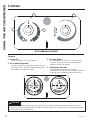
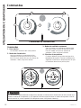
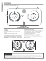
Controls
Controls
1. Power Off
The air conditioner is off in this position.
2. Air Conditioning Modes
In these positions, the compressor and fans will run
to provide cold air. The three modes correspond to
low, medium, and high fan speeds.
3. Fan Only Modes
In these modes, the fans will run to circulate air
in the RV. The three modes correspond to low,
medium, and high fan speeds.
4. Temperature Selection
This knob determines the room set point
temperature. Turn this knob to increase or decrease
how cold the air conditioner will make the room.
Features and appearance will vary.
Air Conditioner Controls
OFF
1
2
3
4
OFF
Position
1A
Position
1B
Position
2B
Position
2A
USING THE AIR CONDITIONER
CAUTION
To prevent circuit breaker from tripping, wait a minimum of 3 minutes between turning the compressor off and
then back on (i.e. wait 3 minutes before moving the dial from position 1A to 1B back to 1A or moving from position
2A to 2B back to 2A (pictured above)

49-5000406 Rev. 3 13
USING THE AIR CONDITIONER
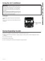
Using the Air Conditioner
IMPORTANT:
• When you turn off the air conditioner, wait at least 3
minutes before turning it back on. This prevents the
compressor from overloading. This 3 minute delay
also applies when switching from cool mode to fan
and back.
• Do not operate your air conditioner in the Cool mode
when the outside temperature is below 60°F (15° C).
The inside evaporator coil may freeze up, and the air
conditioner will not operate properly.
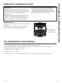
Air Direction
8VHWKHOHYHUWRRSHQRUFORVHYHQWRQIDFHRIFRQWURO
panel.
Open or close 4 side ports to adjust airflow from the air
conditioner.
Front View
Lever is located
between the two
knobs
Normal Operating Sounds
When your air conditioner is operating normally, you may hear sounds such as:
Ŷ'URSOHWVRIZDWHUKLWWLQJWKHFRQGHQVHUFDXVLQJDSLQJLQJRUFOLFNLQJVRXQG7KHZDWHUGURSOHWVKHOSFRROWKH
condenser.
Ŷ$LUPRYHPHQWIURPWKHIDQ
Ŷ&OLFNVIURPWKHFRQWUROF\FOLQJ
Ŷ$KXPRUSXOVDWLQJQRLVHFDXVHGE\WKHFRPSUHVVRUF\FOLQJRQDQGRII

14 49-5000406 Rev. 3
CARE AND CLEANING
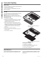
Care and Cleaning
Indoor Panel
Turn the air conditioner off and disconnect power from the
air conditioner before cleaning.
To clean, use water and a mild detergent. Do not use
bleach or abrasives.
Annual Maintenance
Your air conditioner needs annual maintenance to help
ensure steady, top performance throughout the year.
Call your local authorized dealer to schedule an annual
checkup. The expense of an annual inspection is your
responsibility.
Air Filter
The air filter behind the front grille should be checked at
least every 2 weeks and cleaned if necessary.
DO NOT operate the air conditioner without a filter
because dirt and lint will clog it and reduce performance.
Cleaning the Air Filter
1. Turn off the air conditioner.
2. Remove the air filter and grill assembly by carefully
unsnapping the 6 tabs from the main panel. Then
separate the filter from the grill.
8VHDYDFXXPFOHDQHUWRFOHDQDLUILOWHU,IWKHDLU
filter is very dirty, wash it in warm water with a mild
detergent. Do not wash the air filter in the dishwasher
or use any chemical cleaners. Air dry the air filter
completely before replacing to ensure maximum
efficiency.
4. Reassemble the air filter to the grill.
5. Carefully reassemble the grill and filter assembly to
the main panel.
6. Turn on the air conditioner.
Cleaning the Front Panel
1. Turn off the air conditioner.
2. Clean the front panel with a soft, damp cloth.
3. Air dry the front panel completely.
4. Turn on the air conditioner.
Push both tabs toward the GE logo to
release the cover.
Push on the back side of the filter to
release the cover.

49-5000406 Rev. 3 15
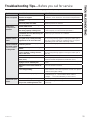
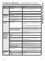
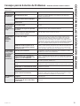
Troubleshooting Tips... Before you call for service
Save time and money! Review the charts on the following pages first and you may not need to call for service.
Problem Possible Cause What To Do
Air Conditioner
does not operate
An RV fuse has blown, or circuit
breaker has tripped.
Replace the fuse or reset the circuit breaker. If the problem
continues, call an electrician. See “Electrical Requirements.”
The mode setting is in the OFF
position.
Press POWER or turn the Mode control to an active setting.
The local power has failed. Wait for power to be restored.
Air conditioner
blows fuses
or trips circuit
breakers
Too many appliances are being used
on the same circuit.
8QSOXJRUUHORFDWHDSSOLDQFHVWKDWVKDUHWKHVDPHFLUFXLW
Time-delay fuse or circuit breaker of
the wrong capacity is being used.
Replace with a time-delay fuse or circuit breaker of the
correct capacity. See “Electrical Requirements.”
You are trying to restart the air
conditioner too soon after turning off
the air conditioner.
Wait at least 3 minutes after turning off the air conditioner
before trying to restart the air conditioner.
Air conditioner
seems to run too
much
The air conditioner is in a heavily
occupied room, or heat-producing
appliances are in use in the room.
8VHH[KDXVWYHQWIDQVZKLOHFRRNLQJRUEDWKLQJDQGWU\QRW
to use heat producing appliances during the hottest part of
the day. A higher capacity air conditioner may be required
depending on the size of the room being cooled.
Air conditioner
cycles on and off
too much or does
not cool room in
cooling mode
The air conditioner is not properly
sized for your RV.
Check the cooling capabilities of your RV air conditioner.
The filter is dirty or obstructed by
debris.
Clean the filter.
There is excessive heat or moisture
(open container cooking, showers,
etc.) in the room.
8VHDIDQWRH[KDXVWKHDWRUPRLVWXUHIURPWKHURRP7U\QRW
to use heat-producing appliances during the hottest part of
the day.
The louvers or ducts are closed. Make sure louvers are open.
The outside temperature is below
60°F (15°C).
Do not try to operate your air conditioner in the cooling mode
when the outside temperature is below 60°F (15°C).
The temperature of the room you are
trying to cool is extremely hot.
Allow extra time for the air conditioner to cool off a very hot
room.
Windows or doors to the outside are
open.
Close all windows and doors.
The Temperature control is not at a
cool enough setting.
Adjust the TEMP control to a cooler setting by pressing the
minus button to reduce the temperature. Set the Fan Speed
control to the highest setting.
Wall thermostat improperly installed Verify proper installation of Wall Thermostat per installation
instructions (pg. 5 …not on exterior wall or in direct
sunlight… …in an area affected by a vent or duct…)
Water drips from
cabinet into your
house
The indoor coil may be frozen. De-ice by running the fan only until clear.
The air conditioner’s mounting gasket
may not be sealed against the roof.
Check mounting bolts and tighten to 45 ± 5 in-lbs if
necessary.
TROUBLESHOOTING

16 49-5000406 Rev. 3
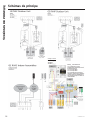
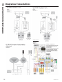
SCHEMATIC DIAGRAMS
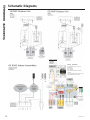
Schematic Diagrams
RARWT_ _DIP Switches
#1 selects between Cool only and
Heat-Pump
#2 is not used
#3 is not used
#4 is used to disable Furnace Mode
selection.
This is for installs where a furnace is not
connected to the RVAC control.
Ceiling Controls
• RARMC__ __
• RARWT__ __
• RAREC__ __

49-5000406 Rev. 3 17
LIMITED WARRANTY
GE Appliances Air Conditioner Limited Warranty
ŶImproper installation, delivery or maintenance. If you
have an installation problem, or if the air conditioner
is of improper cooling capacity for the intended use,
contact your dealer or installer. You are responsible
for providing adequate electrical connecting facilities.
ŶFailure of the product resulting from modifications
to the product or due to unreasonable use including
failure to provide reasonable and necessary
maintenance.
Ŷ/DERUQHFHVVDU\WRPRYHWKHXQLWWRDORFDWLRQZKHUH
it is accessible for service by an individual technician.
ŶReplacement of house fuses or resetting of circuit
breakers.
ŶDamage to the product caused by improper power
supply voltage, accident, fire, floods or acts of God.
ŶIncidental or consequential damage caused by
possible defects with this air conditioner.
ŶDamage caused after delivery.
What GE Appliances Will Not Cover:
This limited warranty is extended to the original purchaser and any succeeding owner for products purchased
IRU59XVHZLWKLQWKH86$DQG&DQDGD,IWKHSURGXFWLVORFDWHGLQDQDUHDZKHUHVHUYLFHE\DQDXWKRUL]HG59
servicer is not available, you may be required to bring the product to an authorized service location for service.
Authorized GE Service location for service.
Some states do not allow the exclusion or limitation of incidental or consequential damages. This limited warranty
gives you specific legal rights, and you may also have other rights which vary from state to state. To know what your
legal rights are, consult your local or state consumer affairs office or your state’s Attorney General.
Warrantor: GE Appliances, a Haier company
Louisville, KY 40225
All warranty service must be provided by certified RV Service Centers.
To schedule service call 1-877-540-7837
Have serial number and model number available when calling for service.
EXCLUSION OF IMPLIED WARRANTIES—Your sole and exclusive remedy is product repair as provided in this
Limited Warranty. Any implied warranties, including the implied warranties of merchantability or fitness for a
particular purpose, are limited to two years or the shortest period allowed by law.
For The Period Of: GE Appliances Will Replace:
Two Years
From the date of the
original purchase
Any part of the air conditioner which fails due to a defect in materials or workmanship.
During this limited two-year warranty, GE Appliances will also cover all labor and
related service to replace the defective part.
Staple your receipt here. Proof of the original purchase
date is needed to obtain service under the warranty.

18 49-5000406 Rev. 3
Printed in China
Consumer Support
CONSUMER SUPPORT
GE Appliances Website
Have a question or need assistance with your appliance? Try the GE Appliances Website 24 hours a day, any day
of the year! You can also shop for more great GE Appliances products and take advantage of all our on-line support
VHUYLFHVGHVLJQHGIRU\RXUFRQYHQLHQFH,QWKH86GEAppliances.com
Register Your Appliance
Register your new appliance on-line at your convenience! Timely product registration will allow for enhanced
communication and prompt service under the terms of your warranty, should the need arise. You may also mail in
WKHSUHSULQWHGUHJLVWUDWLRQFDUGLQFOXGHGLQWKHSDFNLQJPDWHULDO,QWKH86GEAppliances.com/register
Schedule Service
Call 1-877-540-7837 during normal business hours.
Extended Warranties
Purchase a GE Appliances extended warranty and learn about special discounts that are available while your
warranty is still in effect. You can purchase it on-line anytime. GE Appliances Services will still be there after your
ZDUUDQW\H[SLUHV,QWKH86GEAppliances.com/extended-warranty or call 800.626.2224 during normal
business hours.
Remote Connectivity
For assistance with wireless network connectivity (for models with remote enable),
visit our website at GEAppliances.com/connected-home-smart-appliancesRUFDOOLQWKH86
Parts and Accessories
Individuals qualified to service their own appliances can have parts or accessories sent directly to their homes
(VISA, MasterCard and Discover cards are accepted). Order on-line today 24 hours every day.
,QWKH86GEApplianceparts.com or by phone at 877.959.8688 during normal business hours.
Instructions contained in this manual cover procedures to be performed by any user. Other servicing
generally should be referred to qualified service personnel. Caution must be exercised, since improper
servicing may cause unsafe operation.
Contact Us
If you are not satisfied with the service you receive from GE Appliances, contact us on our Website with all the
details including your phone number, or write to:
General Manager, Customer Relations | GE Appliances, Appliance Park | Louisville, KY 40225
GEAppliances.com/contact

GE est une marque déposée de General Electric Company. Fabriqué sous licence de marque.
MANUEL
D’UTILISATION
CLIMATISEUR
individuel
49-5000406 Rev. 3 12-20 GEA
INFORMATION DE SÉCURITÉ ...3
INSTRUCTIONS D’INSTALLATION
Avant de commencer ..................4
Outils dont vous pouvez avoir besoin ......4
RARMN_ _: Pièces incluses ..............5
RAREN_ _: Pièces incluses ..............6
RARED_ _: Pièces incluses ..............7
Exigences et détermination de
l’emplacement d’installation sur le toit . . .8
Exigences et préparation du toit .........9
Exigences électriques ..................9
Mise en place de l’appareil sur le toit .....9
Nstallation de l’appareil ...............10
Instr. Pour électricité .................. 11
UTILISANT LE CONDITIONNEUR
D’AIR
Commandes .........................12
Orientation de l’air ...................13
Ces phénomènes sont normaux ........13
ENTRETIEN ET NETTOYAGE
Panneau intérieur .....................14
Filtre à air .............................. 14
Maintenance annuelle ................... 14
CONSEILS DE DÉPANNAGE ....15
SCHÉMAS DE PRINCIPE ........16
GARANTIE LIMITÉE .............17
SOUTIEN
AU CONSOMMATEUR ...........18
Unités de toit :
ARC13AAC_
ARC15AAC_
ARC13AHC_
ARH15AAC_
Assemblages intérieurs
RARMN_ _
RAREN_ _
RARED_ _
FRANÇAIS
Écrivez le modèle et les numéros de
série ici:
Modèle # ______________
Serial # _______________
Vous pouvez les trouver sur une
étiquette sur le climatiseur.

2 49-5000406 Rev. 3
NOUS VOUS REMERCIONS D’ACCUEILLIR GE APPLIANCES CHEZ VOUS RV
Que vous ayez grandi avec GE Appliances ou qu’il s’agisse de votre première acquisition, nous
sommes heureux de vous accueillir dans notre famille.
Nous sommes fiers du savoir-faire, de l’innovation et de l’esthétique qui composent chaque appareil
GE Appliances, et nous pensons que vous le serez aussi. Dans cette optique, nous vous rappelons
que l’enregistrement de votre électroménager vous assure la communication de renseignements
importants sur le produit et la garantie lorsque vous en avez besoin.
Enregistrez votre électroménager GE en ligne dès maintenant. Des sites Web et des numéros de
téléphone utiles figurent dans la section Soutien au consommateur de ce manuel d’utilisation.
La page est en cours de chargement...
La page est en cours de chargement...
La page est en cours de chargement...
La page est en cours de chargement...
La page est en cours de chargement...
La page est en cours de chargement...
La page est en cours de chargement...
La page est en cours de chargement...
La page est en cours de chargement...
La page est en cours de chargement...
La page est en cours de chargement...
La page est en cours de chargement...
La page est en cours de chargement...
La page est en cours de chargement...
La page est en cours de chargement...
La page est en cours de chargement...
La page est en cours de chargement...
La page est en cours de chargement...
La page est en cours de chargement...
La page est en cours de chargement...
La page est en cours de chargement...
La page est en cours de chargement...
La page est en cours de chargement...
La page est en cours de chargement...
La page est en cours de chargement...
La page est en cours de chargement...
La page est en cours de chargement...
La page est en cours de chargement...
La page est en cours de chargement...
La page est en cours de chargement...
La page est en cours de chargement...
La page est en cours de chargement...
La page est en cours de chargement...
La page est en cours de chargement...
-
 1
1
-
 2
2
-
 3
3
-
 4
4
-
 5
5
-
 6
6
-
 7
7
-
 8
8
-
 9
9
-
 10
10
-
 11
11
-
 12
12
-
 13
13
-
 14
14
-
 15
15
-
 16
16
-
 17
17
-
 18
18
-
 19
19
-
 20
20
-
 21
21
-
 22
22
-
 23
23
-
 24
24
-
 25
25
-
 26
26
-
 27
27
-
 28
28
-
 29
29
-
 30
30
-
 31
31
-
 32
32
-
 33
33
-
 34
34
-
 35
35
-
 36
36
-
 37
37
-
 38
38
-
 39
39
-
 40
40
-
 41
41
-
 42
42
-
 43
43
-
 44
44
-
 45
45
-
 46
46
-
 47
47
-
 48
48
-
 49
49
-
 50
50
-
 51
51
-
 52
52
-
 53
53
-
 54
54


dans d''autres langues
- English: GE ARC13AACB User guide
- español: GE ARC13AACB Guía del usuario
Documents connexes
Autres documents
-
Hitachi RPI-4.0FSN2SQ Installation & Maintenance Manual
-
York Water Source Heat Pump and Heat Recovery Outdoor Units 208-460V Guide d'installation
-
 GE Monogram GEZV950SDSS DL 5d7bc61df13207f0d1d3b946cc81
-
Faber GLASIS36SS600B Guide d'installation
-
Empire DVP36PP32EN-3 Le manuel du propriétaire
-
Fujitsu AOGG24LAT3 Guide d'installation
-
Dometic DFSAD12, DFSD12, DFSD16, DFSD20, DFMD16,DFMD20, DFMD25, DFMD30, DFMD35, DFLD35,DFLD40, DFLA35, DFLA40 Mode d'emploi
