Lincoln Electric SA-400I Mode d'emploi
- Catégorie
- Système de soudage
- Taper
- Mode d'emploi

Operator’s Manual
SA-400I
®
Register your machine:
www.lincolnelectric.com/register
Authorized Service and Distributor Locator:
www.lincolnelectric.com/locator
IM10192-A | Issue D ate
Nov-18
© Lincoln Global, Inc. All Rights Reserved.
For use with machines having Code Numbers:
12267, 12459, 12543
Need Help? Call 1.888.935.3877
to talk to a Service Representative
Hours of Operation:
8:00 AM to 6:00 PM (ET) Mon. thru Fri.
After hours?
Use “Ask the Experts” at lincolnelectric.com
A Lincoln Service Representative will contact you
no later than the following business day.
For Service outside the USA:
Email: [email protected]
Save for future reference
Date Purchased
Code: (ex: 10859)
Serial: (ex: U1060512345)

THANK YOU FOR SELECTING
A QUALITY PRODUCT BY
LINCOLN ELEC TRIC.
PLEASE EXAMINE CARTON AND EQUIPMENT FOR
DAMAGE IMMEDIATELY
When this equipment is shipped, title passes to the purchaser
upon receipt by the carrier. Consequently, claims for material
damaged in shipment must be made by the purchaser against the
transportation company at the time the shipment is received.
SAFETY DEPENDS ON YOU
Lincoln arc welding and cutting equipment is designed and built
with safety in mind. However, your overall safety can be increased
by proper installation ... and thoughtful operation on your part.
DO NOT INSTALL, OPERATE OR REPAIR THIS EQUIPMENT
WITHOUT READING THIS MANUAL AND THE SAFETY
PRECAUTIONS CONTAINED THROUGHOUT. And, most importantly,
think before you act and be careful.
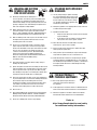
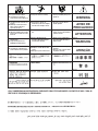
This statement appears where the information must be followed
exactly to avoid serious personal injury or loss of life.
This statement appears where the information must be followed
to avoid minor personal injury or damage to this equipment.
KEEP YOUR HEAD OUT OF THE FUMES.
DON’T get too close to the arc.
U
se corrective lenses if necessary
to stay a reasonable distance
away from the arc.
READ and obey the Safety Data
Sheet (SDS) and the warning label
that appears on all containers of
welding materials.
USE ENOUGH VENTILATION or
exhaust at the arc, or both, to
keep the fumes and gases from
your breathing zone and the general area.
IN A LARGE ROOM OR OUTDOORS, natural ventilation may be
adequate if you keep your head out of the fumes (See below).
USE NATURAL DRAFTS or fans to keep the fumes away
from your face.
If you de velop unusual symptoms, see your supervisor.
Perhaps the welding atmosphere and ventilation system
should be checked.
WEAR CORRECT EYE, EAR &
BODY PROTECTION
PROTECT your eyes and face with welding helmet
properly fitted and with proper grade of filter plate
(See ANSI Z49.1).
PROTECT your body from welding spatter and arc
flash with protective clothing including woolen
clothing, flame-proof apron and gloves, leather
leggings, and high boots.
PROTECT others from splatter, flash, and glare
with protective screens or barriers.
IN SOME AREAS, protection from noise may be appropriate.
BE SURE protective equipment is in good condition.
Also, wear safety glasses in work area
AT ALL TIMES.
SPECIAL SITUATIONS
DO NOT WELD OR CUT containers or materials which previously
had been in contact with hazardous substances unless they are
properly cleaned. This is extremely dangerous.
DO NOT WELD OR CUT painted or plated parts unless special
precautions with ventilation have been taken. They can release
highly toxic fumes or gases.
Additional precautionary measures
PROTECT compressed gas cylinders from excessive heat,
mechanical shocks, and arcs; fasten cylinders so they cannot fall.
BE SURE cylinders are never grounded or part of an
electrical circuit.
REMOVE all potential fire hazards from welding area.
ALWAYS HAVE FIRE FIGHTING EQUIPMENT READY FOR
IMMEDIATE USE AND KNOW HOW TO USE IT.
WARNING
CAUTION
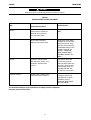
Safety 01 of 04 - 06/15/2016

SECTION A:
WARNINGS
CALIFORNIA PROPOSITION 65 WARNINGS
Diesel Engines
Diesel engine exhaust and some of its constituents are known
to the State of California to cause cancer, birth defects, and other
reproductive harm.
Gasoline Engines
The engine exhaust from this product contains chemicals known
to the State of California to cause cancer, birth defects, or other
reproductive harm.
ARC WELDING CAN BE HAZARDOUS. PROTECT
YOURSELF AND OTHERS FROM POSSIBLE SERIOUS
INJURY OR DEATH. KEEP CHILDREN AWAY.
PACEMAKER WEARERS SHOULD CONSULT WITH
THEIR DOCTOR BEFORE OPERATING.
Read and understand the following safety highlights. For
additional safety information, it is strongly recommended
that you purchase a copy of “Safety in Welding & Cutting -
ANSI Standard Z49.1” from the American Welding Society,
P.O. Box 351040, Miami, Florida 33135 or CSA Standard
W117.2-1974. A Free copy of “Arc Welding Safety” booklet
E205 is available from the Lincoln Electric Company,
22801 St. Clair Avenue, Cleveland, Ohio 44117-1199.
BE SURE THAT ALL INSTALLATION, OPERATION,
MAINTENANCE AND REPAIR PROCEDURES ARE
PERFORMED ONLY BY QUALIFIED INDIVIDUALS.
FOR ENGINE POWERED
EQUIPMENT.
1.a. Turn the engine off before troubleshooting
and maintenance work unless the
maintenance work requires it to be running.
1.b. Operate engines in open, well-ventilated
areas or vent the engine exhaust fumes outdoors.
1.c. Do not add the fuel near an open flame
welding arc or when the engine is running.
Stop the engine and allow it to cool before
refueling to prevent spilled fuel from
vaporizing on contact with hot engine parts
and igniting. Do not spill fuel when filling
tank. If fuel is spilled, wipe it up and do not start engine until
fumes have been eliminated.
1.d. Keep all equipment safety guards, covers
and devices in position and in good repair.
Keep hands, hair, clothing and tools away
from V-belts, gears, fans and all other
moving parts when starting, operating or
repairing equipment.
1.e. In some cases it may be necessary to remove safety guards to
perform required maintenance. Remove guards only when
necessary and replace them when the maintenance requiring
t
heir removal is complete. Always use the greatest care when
working near moving parts.
1.f. Do not put your hands near the engine fan. Do not attempt to
override the governor or idler by pushing on the throttle control
rods while the engine is running.
1.g. To prevent accidentally starting gasoline engines while turning
the engine or welding generator during maintenance work,
disconnect the spark plug wires, distributor cap or magneto wire
as appropriate.
1.h. To avoid scalding, do not remove the radiator
pressure cap when the engine is
hot.
ELECTRIC AND
MAGNETIC FIELDS MAY
BE DANGEROUS
2.a. Electric current flowing through any conductor
causes localized Electric and Magnetic Fields (EMF).
Welding current creates EMF fields around welding cables
and welding machines
2.b. EMF fields may interfere with some pacemakers, and
welders having a pacemaker should consult their physician
before welding.
2.c. Exposure to EMF fields in welding may have other health effects
which are now not known.
2.d. All welders should use the following procedures in order to
minimize exposure to EMF fields from the welding circuit:
2.d.1. Route the electrode and work cables together - Secure
them with tape when possible.
2.d.2. Never coil the electrode lead around your body.
2.d.3. Do not place your body between the electrode and work
cables. If the electrode cable is on your right side, the
work cable should also be on your right side.
2.d.4. Connect the work cable to the workpiece as close as pos-
sible to the area being welded.
2.d.5. Do not work next to welding power source.
SAFETY
Safety 02 of 04 - 06/15/2016

ELECTRIC SHOCK
CAN KILL.
3.a. The electrode and work (or ground) circuits are
electrically “hot” when the welder is on. Do
not touch these “hot” parts with your bare skin or wet clothing.
Wear dry, hole-free gloves to insulate hands.
3.b. Insulate yourself from work and ground using dry insulation.
Make certain the insulation is large enough to cover your full area
o
f physical contact with work and ground.
In addition to the normal safety precautions, if
welding must be performed under electrically
hazardous conditions (in damp locations or while
wearing wet clothing; on metal structures such as
floors, gratings or scaffolds; when in cramped
positions such as sitting, kneeling or lying, if there
is a high risk of unavoidable or accidental contact
with the workpiece or ground) use the following
equipment:
• Semiautomatic DC Constant Voltage (Wire) Welder.
• DC Manual (Stick) Welder.
• AC Welder with Reduced Voltage Control.
3.c. In semiautomatic or automatic wire welding, the electrode,
electrode reel, welding head, nozzle or semiautomatic welding
gun are also electrically “hot”.
3.d. Always be sure the work cable makes a good electrical
connection with the metal being welded. The connection should
be as close as possible to the area being welded.
3.e. Ground the work or metal to be welded to a good electrical (earth)
ground.
3.f. Maintain the electrode holder, work clamp, welding cable and
welding machine in good, safe operating condition. Replace
damaged insulation.
3.g. Never dip the electrode in water for cooling.
3.h. Never simultaneously touch electrically “hot” parts of electrode
holders connected to two welders because voltage
between the
two can be the total of the open circuit voltage of both
welders.
3.i. When working above floor level, use a safety belt to protect
yourself from a fall should you get a shock.
3.j. Also see It ems 6.c. and 8.
ARC RAYS CAN BURN.
4.a. Use a shield with the proper filter and cover plates to protect your
eyes from sparks and the rays of the arc when welding or
observing open arc welding. Headshield and filter lens should
conform to ANSI Z87. I standards.
4.b. Use suitable clothing made from durable flame-resistant material
to protect your skin and that of your helpers from the arc rays.
4.c. Protect other nearby personnel with suitable, non-flammable
screening and/or warn them not to watch the arc nor expose
themselves to the arc rays or to hot spatter or metal.
FUMES AND GASES
CAN BE DANGEROUS.
5.a. Welding may produce fumes and gases
hazardous to health. Avoid breathing these fumes and gases.
When welding, keep your head out of the fume. Use enough
ventilation and/or exhaust at the arc to keep fumes and gases
away from the breathing zone. When welding hardfacing
(see instructions on container or SDS) or on lead
or cadmium plated steel and other metals or
coatings which produce highly toxic fumes, keep
exposure as low as possible and within applicable
OSHA PEL and ACGIH TLV limits using local
exhaust or mechanical ventilation unless exposure
assessments indicate otherwise. In confined
spaces or in some circumstances, outdoors, a
respirator may also be required. Additional
precautions are also required when welding
on galvanized steel.
5. b. The operation of welding fume control equipment is affected by
various factors including proper use and positioning of the
equipment, maintenance of the equipment and the specific
welding procedure and application involved. Worker exposure
level should be checked upon installation and periodically
thereafter to be certain it is within applicable OSHA PEL and
ACGIH TLV limits.
5.c. Do not weld in locations near chlorinated hydrocarbon vapors
coming from degreasing, cleaning or spraying operations. The
heat and rays of the arc can react with solvent vapors to form
phosgene, a highly toxic gas, and other irritating products.
5.d. Shielding gases used for arc welding can displace air and
cause
injury or death. Always use enough ventilation, especially in
confined areas, to insure breathing air is safe.
5.e. Read and understand the manufacturer’s instructions for this
equipment and the consumables to be used, including the
Safety Data Sheet (SDS) and follow your employer’s safety
practices. SDS forms are available from your welding
distributor or from the manufacturer.
5.f. Also see item 1.b.
SAFETY
Safety 03 of 04 - 06/15/2016

WELDING AND CUTTING
SPARKS CAN CAUSE
FIRE OR EXPLOSION.
6.a. Remove fire hazards from the welding area. If
this is not possible, cover them to prevent the welding sparks
f
rom starting a fire. Remember that welding sparks and hot
materials from welding can easily go through small cracks and
openings to adjacent areas. Avoid welding near hydraulic lines.
Have a fire extinguisher readily available.
6.b. Where compressed gases are to be used at the job site, special
precautions should be used to prevent hazardous situations.
Refer to “Safety in Welding and Cutting” (ANSI Standard Z49.1)
and the operating information for the equipment being used.
6.c. When not welding, make certain no part of the electrode circuit is
touching the work or ground. Accidental contact can cause
overheating and create a fire hazard.
6.d. Do not heat, cut or weld tanks, drums or containers until the
proper steps have been taken to insure that such procedures
will not cause flammable or toxic vapors from substances inside.
They can cause an explosion even though they have been
“cleaned”. For information, purchase “Recommended Safe
Practices for the Preparation for Welding and Cutting of
Containers and Piping That Have Held Hazardous Substances”,
AWS F4.1 from the American Welding Society
(see address above).
6.e. Vent hollow castings or containers before heating, cutting or
welding. They may explode.
6.f. Sparks and spatter are thrown from the welding arc. Wear oil free
protective garments such as leather gloves, heavy shirt, cuffless
trousers, high shoes and a cap over your hair. Wear ear plugs
when welding out of position or in confined places. Always wear
safety glasses with side shields when in a welding area.
6.g. Connect the work cable to the work as close to the welding area
as practical. Work cables connected to the building framework or
other locations away from the welding area increase the
possibility of the welding current passing through lifting chains,
crane cables or other alternate circuits. This can create fire
hazards or overheat lifting chains or cables until they fail.
6.h. Also see item 1.c.
6.I. Read and follow NFPA 51B “Standard for Fire Prevention During
Welding, Cutting and Other Hot Work”, available from NFPA, 1
Batterymarch Park, PO box 9101, Quincy, MA 022690-9101.
6.j. Do not use a welding power source for pipe thawing.
CYLINDER MAY EXPLODE IF
DAMAGED.
7.a. Use only compressed gas cylinders containing
the correct shielding gas for the process used
and properly operating regulators designed for
the gas and pressure used. All hoses, fittings,
e
tc. should be suitable for the application and
maintained in good condition.
7.b. Always keep cylinders in an upright position securely chained to
an undercarriage or fixed support.
7.c. Cylinders should be located:
• Away from areas where they may be struck or subjected
to physical damage.
• A safe distance from arc welding or cutting operations
and any other source of heat, sparks, or flame.
7.d. Never allow the electrode, electrode holder or any other
electrically “hot” parts to touch a cylinder.
7.e. Keep your head and face away from the cylinder valve outlet
when opening the cylinder valve.
7.f. Valve protection caps should always be in place and hand tight
except when the cylinder is in use or connected for use.
7.g. Read and follow the instructions on compressed gas cylinders,
associated equipment, and CGA publication P-l, “Precautions for
Safe Handling of Compressed Gases in Cylinders,” available from
the Compressed Gas Association, 14501 George Carter Way
Chantilly, VA 20151.
FOR ELECTRICALLY
POWERED EQUIPMENT.
8.a. Turn off input power using the disconnect
switch at the fuse box before working on
the equipment.
8.b. Install equipment in accordance with the U.S. National Electrical
Code, all local codes and the manufacturer’s recommendations.
8.c. Ground the equipment in accordance with the U.S. National
Electrical Code and the manufacturer’s recommendations.
Refer to
http://www.lincolnelectric.com/safety
for additional safety information.
SAFETY
Safety 04 of 04 - 06/15/2016

2
SAFETY
PRÉCAUTIONS DE SÛRETÉ
Pour
votre propre protection lire et observer toutes les instructions et les pré-
cautions de sûreté specifiques qui parraissent dans ce manuel aussi bien que
les précautions de sûreté générales suivantes:
Sûreté Pour Soudage A L’Arc
1. Protegez-vous contre la secousse électrique:
a. Les circuits à l’électrode et à la piéce sont sous tension quand la
machine à souder est en marche. Eviter toujours tout contact entre les
parties sous tension et la peau nue ou les vétements mouillés. Porter
des gants secs et sans trous pour isoler les mains.
b. Faire trés attention de bien s’isoler de la masse quand on soude dans
des endroits humides, ou sur un plancher metallique ou des grilles
metalliques, principalement dans les positions assis ou couché
pour lesquelles une grande partie du corps peut être en contact avec
la masse.
c. Maintenir le porte-électrode, la pince de masse, le câble de soudage
et la machine à souder en bon et sûr état defonctionnement.
d.Ne jamais plonger le porte-électrode dans l’eau pour le refroidir.
e. Ne jamais toucher simultanément les parties sous tension des porte-
électrodes connectés à deux machines à souder parce que la tension
entre les deux pinces peut être le total de la tension à vide des deux
machines.
f. Si on utilise la machine à souder comme une source de courant pour
soudage semi-automatique, ces precautions pour le porte-électrode
s’applicuent aussi au pistolet de soudage.
2. Dans le cas de travail au dessus du niveau du sol, se protéger contre les
chutes dans le cas ou on recoit un choc. Ne jamais enrouler le câble-élec-
trode autour de n’importe quelle partie du corps.
3. Un coup d’arc peut être plus sévère qu’un coup de soliel, donc:
a. Utiliser un bon masque avec un verre filtrant approprié ainsi qu’un
verre blanc afin de se protéger les yeux du rayonnement de l’arc et
des projections quand on soude ou quand on regarde l’arc.
b. Porter des vêtements convenables afin de protéger la peau de soudeur
et des aides contre le rayonnement de l‘arc.
c. Protéger l’autre personnel travaillant à proximité au soudage à l’aide
d’écrans appropriés et non-inflammables.
4. Des gouttes de laitier en fusion sont émises de l’arc de soudage. Se pro-
téger avec des vêtements de protection libres de l’huile, tels que les gants
en cuir, chemise épaisse, pantalons sans revers, et chaussures mon-
tantes.
5. Toujours porter des lunettes de sécurité dans la zone de soudage. Utiliser
des lunettes avec écrans lateraux dans les zones où l’on pique le laitier.
6. Eloigner les matériaux inflammables ou les recouvrir afin de prévenir tout
risque d’incendie dû aux étincelles.
7. Quand on ne soud
e pas, poser la pince à une endroit isolé de la masse. Un
court-circuit accidental peut provoquer un échauffement et un risque d’in-
cendie.
8. S’assurer que la masse est connectée le plus prés possible de la zone de
travail qu’il est pratique de le faire. Si on place la masse sur la charpente
de la construction ou d’autres endroits éloignés de la zone de travail, on
augmente le risque de voir passer le courant de soudage par les chaines
de levage, câbles de grue, ou autres circuits. Cela peut provoquer des
risques d’incendie ou d’echauffement des chaines et des câbles jusqu’à
ce qu’ils se rompent.
9. Assurer une ventilation suffisante dans la zone de soudage. Ceci est parti-
culiérement important pour le soudage de tôles galvanisées plombées, ou
cadmiées ou tout autre métal qui produit des fumeés toxiques.
10. Ne pas souder en présence de vapeurs de chlore provenant d’opérations de
dégraissage, nettoyage ou pistolage. La chaleur ou les rayons de l’arc
peuvent réagir avec les vapeurs du solvant pour produire du phosgéne
(gas fortement toxique) ou autres produits irritants.
11. Pour obtenir de plus amples renseignements sur la sûreté, voir le code
“Code for safety in welding and cutting” CSA Standard W 117.2-1974.
PRÉCAUTIONS DE SÛRETÉ POUR
LES MACHINES À SOUDER À
TRANSFORMATEUR ET À
REDRESSEUR
1. Relier à la terre le chassis du poste conformement au code de l’électricité
et aux recommendations du fabricant. Le dispositif de montage ou la
piece à souder doit être branché à une bonne mise à la terre.
2. Autant que possible, I’installation et l’entretien du poste seront effectués
par un électricien qualifié.
3. Avant de faires des travaux à l’interieur de poste, la debrancher à l’inter-
rupteur à la boite de fusibles.
4. Garder tous les couvercles et dispositifs de sûreté à leur place.

Page
________________________________________________________________________________
Installation...............................................................................................................................Section A
Technical Specifications...............................................................................................................A-1
General Description......................................................................................................................A-2
Design Features...........................................................................................................................A-2
Pre-Operation Installation.............................................................................................................A-3
Safety Precautions................................................................................................................A-3
Exhaust Spark Arrester.........................................................................................................A-3
Location/Ventilation .....................................................................................................................A-3
Angle of Operation................................................................................................................A-4
Machine Grounding......................................................................................................................A-4
Lift Bail ........................................................................................................................................A-4
Trailers ........................................................................................................................................A-4
Vehicle Mounting..................................................................................................................A-5
Polarity Control and Cable Sizes...................................................................................................A-5
Pre-Operation Service..................................................................................................................A-5
Oil, Fuel .......................................................................................................................................A-5
Cooling System............................................................................................................................A-5
Battery Charging..........................................................................................................................A-6
Electrical Devices use with this Product................................................................................A-7
________________________________________________________________________________
Operation.................................................................................................................................Section B
Engine Operation .........................................................................................................................B-1
Starting The Perkins Engine .........................................................................................................B-1
High Altitude Operation, Stopping the engine........................................................................B-1
Engine Break-In ...........................................................................................................................B-2
Welder Operation .........................................................................................................................B-2
Duty Cycle............................................................................................................................B-2
Current Control.....................................................................................................................B-2
Remote Control How to Set Controls for Stick Welding..........................................................B-2
MIG Welding ................................................................................................................................B-3
Idler Operation, Auxiliary Power, Fuel Consumption Data ......................................................B-3
________________________________________________________________________________
Accessories .............................................................................................................................Section C
Optional Features (Field Installed) ................................................................................................C-1
________________________________________________________________________________
Maintenance............................................................................................................................Section D
Safety Precautions.......................................................................................................................D-1
General Instructions.....................................................................................................................D-1
Cooling System............................................................................................................................D-1
Bearings......................................................................................................................................D-1
Commutator and Brushes ............................................................................................................D-1
Nameplates .................................................................................................................................D-2
Purging Air from Fuel System ......................................................................................................D-2
Engine Service Chart ...................................................................................................................D-3
GFCI Testing and Resetting Procedure .........................................................................................D-4
________________________________________________________________________________
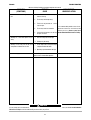
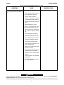
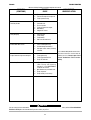
Troubleshooting.......................................................................................................................Section E
Safety Precautions .......................................................................................................................E-1
Welder Troubleshooting ...............................................................................................................E-2
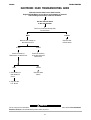
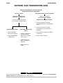
Electronic Idler Troubleshooting Guide ...................................................................................E-3,E-4
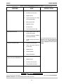
Engine Troubleshooting Guide .......................................................................................E-5 thru E-8
TABLE OF CONTENTS
SA-400I
®

________________________________________________________________________________
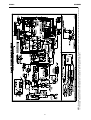
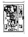
Diagrams..................................................................................................................................Section F
Wiring Diagram ............................................................................................................................F-1
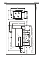
Dimension Print............................................................................................................................F-2
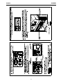
RCD Installation Instruction Print ..................................................................................................F-3
________________________________________________________________________________
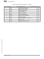
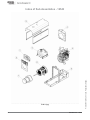
Parts List........................................................................................................parts.lincolnelectric.com
Content/details may be changed or updated without notice. For most current Instruction Manuals, go to
parts.lincolnelectric.com.
TABLE OF CONTENTS
SA-400I
®

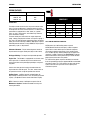
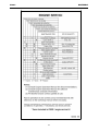
DESCRIPTION RATED DC OUTPUT * DUTY
VOLTS @ RATED AMPS CYCLE
300 Amp DC Welder 30V @ 250A 100%
All Copper Windings 32V @ 300A 60%
Pure DC Power Generator 25V @ 400A 35%
90V DC Max.
OCV @ 1800RPM
DC CURRENT RANGE FINE
ADJUSTMENT IN EACH RANGE
40-400 Amps
240- Max
260-170 Amps
190-120 Amps
130-80 Amps
Min-90 Amps
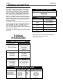
GENERAL DESCRIPTION
The SA-400I
®
is a heavy duty, engine driven, DC arc welding
power source, capable of providing constant current output for
s
tick welding or DC TIG welding. This welder is wound with all
copper coils, rated at 400 amps/25 Volts, and provides other
Classic
®
features such as improved door latches and stainless
hinges. With the addition of the optional K3964-1 Wire Feed
Module™, the SA-400I
®
will provide constant voltage output for
running the LN-7, LN-23P, or LN-25 wire feeders. The optional
K924-5 Remote Control Kit, provides a remote control rheostat for
remote fine current and open circuit voltage adjustment. See
Section C for description.
The SA-400I
®
has an Electronic Engine Protection System. In the
event of sudden low oil pressure or high coolant temperature, the
engine immediately shuts down. The SA-400I
®
has a current
range of 40-400 DC amps with output ratings as follows:
These units are also capable of providing 3 kVA of 120/240 volts
of 60 cycle AC auxiliary power.
The SA-400I
®
uses the Perkins 404D-22 industrial water cooled
diesel engine.
TECHNICAL
SPECIFICATIONS
INPUT - DIESEL ENGINE
RATED OUTPUT @ 104°F(40°C) - WELDER
PHYSICAL DIMENSIONS
*
Based on a 10 min. period.
(1) Output rating in watts is equivalent to volt-amperes at unity power factor.
Output voltage is within +/- 10% at all loads up to rated capacity. When
welding, available auxiliary power will be reduced.
(2) Height to top of exhuast elbow.
OUTPUT @ 104°F(40°C) - GENERATOR
M
a
k
e
/
M
o
de
l
P
ERKINS
404D-22 Die
se
l Engine
TIER 4 Inte
rm Co
mplia
nt
Description
4 cylinder Naturally
Aspirated Water Cooled
Diesel Engine
Cast Iron Cylinder Block,
Crankcase
Speed (RPM)
High Idle 1800
Low Idle 1400
Full Load 1725
Displacement
135 cu. in. (2.2 ltrs.)
Bore x Stroke
3.3” x 3.9”
84mm x 100mm
32.7 HP @ 1800 RPM
Starting System
12VDC battery (Group 24,
650 COLD CRANK AMPS)
2.0 KW STARTER
65 A. ALTERNATOR
w/built in reg.
Capacities
Fuel 16 US gal (60.6L)
Oil: 11.2 US gal. (10.6L)
Coolant: 9.5 (9.0L)
Auxiliary Power
(
1)
3,000 Watts Continuous, 60 Hz AC
26 Amps @ 120V
1
3 Amps @ 240V
Model
Height
(2)
Width
Depth
Weight
K4088-1 CSA without
Wire Feed Module
45.5 in (1156 mm)
24.3 in. (616 mm)
65 in. (1651 mm)
1450 lbs. (658 kg) (Approx.)
A-1
INSTALLATIONSA-400I
®

A-2
INSTALLATIONSA-400I
®
DESIGN FEATURES
C
ontrol Panel
The welder controls consist of a five step current selector switch
and a “Fine Current Adjustment” rheostat located on the upper
control panel at the exciter end of the machine. The lower control
panel welder is equipped with a “Start” button, an “Ignition”
switch, an “Idler” control switch, and a “Glow Plug” button for
easier cold weather starting.
The lower control panel also contains an engine temperature
gauge, a battery charging fault indicator, an oil pressure gauge, a
fuel / hour / LED indicator gauge, temperature gauge, for auxiliary
power consists of one 20 amp, 120VAC (5-20R) duplex receptacle
with GFCI protection and one 15 amp, 240VAC (6-15R) receptacle,
protected by 2 pole, 15 Amp breaker.
Voltmeter & Ammeter - Easy to read analog meter for volts &
amps located on the upper control panel (only on code 12459)
All Copper Windings - For long life and dependable operation.
Engine Idler - The SA-400I
®
is equipped with an electronic auto-
matic engine idler. It automatically increases and decreases
engine speed when starting and stopping welding or using auxil-
iary power.
A built-in time delay permits changing electrodes before the
engine slows to its low idle speed. The “Idler” control switch on
the panel locks the idler in high idle position when desired.
Auxiliary Power - 3.0 KVA of nominal 120/240V, 60Hz, AC.
Output voltage is maintained within ± 10% at all loads up to rated
capacity. (See Optional Features Section C for Power Plug Kit.)
GFCI - Protects the 20 amp, 120V duplex receptacle. See the
Maintenance Section for detailed information on testing and
resetting of the GFCI.
120 V DUPLEX RECEPTACLE AND GFCI
A GFCI protects the 120V auxiliary power receptacle.
A GFCI (Ground Fault Circuit Interrupter) is a device to protect
against electric shock should a piece of defective equipment
connected to it develop a ground fault. If this situation should
occur, the GFCI will trip, removing voltage from the output of the
receptacle. If a GFCI is tripped see the MAINTENANCE section for
detailed information on testing and resetting it. A GFCI should be
properly tested at least once every month.
The 120 V auxiliary power receptacle should only be used with
three wire grounded type plugs or approved double insulated tools
with two wire plugs. The current rating of any plug used with the
system must be at least equal to the current capacity of the
associated receptacle.
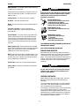
2
50A @ 30V
300A @ 32V
400A @ 25V
1
00%
60%
35%
R
ATED OUTPUT DUTY CYCLE
WELDER OUTPUT RATINGS AT TEMPERATURES
ABOVE 40ºC
AMPS DUTY CYCLE VOLTS TEMPERATURE
340 35% 25 55
360 35% 25 50
380 35% 25 45
300 60% 30 55
300 60% 32 50
250 100% 30 55

A-3
INSTALLATIONSA-400I
®
Welder Enclosure - The complete welder is rubber mounted on
a rugged steel “C” channel base.
The output terminals are placed at the side of the machines so
that they are protected by the door. The output terminals are
labeled (+) and (-).
Cranking System - A 12 volt electric starter is standard.
Air Cleaner - Heavy duty two stage dry type.
Muffler - A muffler and stainless steel exhaust outlet elbow are
standard.
Fuel / Hour / LED gauge - A meter to record hours of
operation, show fuel status, battery charging fault LED and
engine fault LED.
Engine Protection - The system shuts the engine down in the
event of sudden low oil pressure or high coolant temperature.
A warning light on the control panel will indicate such a fault.
To reset the engine for restarting, turn the ignition switch off
then on. Refer to Troubleshooting section for all warning light
fault codes.
Battery Charging Light - A warning indicator light for Low/No
battery charge. The light is off when the systems are functioning
properly. The light will come on if there is a Low/No battery
condition but the machine will continue to run.
NOTE: The light will come on when the Run/Stop switch is in the
“ON” position. It will come on during cranking and stay on until
the engine starts. After, starting the engine the light will go off
unless a Low/No battery condition exists.
Oil Drain Valve - A ball valve, hose and clamp are standard.
Remote Control - The Remote / Local Switch and Receptacle
are standard.
PRE-OPERATION INSTALLATION
EXHAUST SPARK ARRESTER
Some federal, state or local laws may require that engines be
equipped with exhaust spark arresters when they are operated in
certain locations where unarrested sparks may present a fire
hazard. The standard muffler included with this welder does not
qualify as a spark arrester. When required by local regulations,
a suitable spark arrester must be installed and properly
maintained.
Use of an incorrect arrester may lead to engine damage or
performance loss. Contact the engine manufacturer for
specific recommendations.
LOCATION / VENTILATION
Always operate the welder with the doors closed. Leaving the
doors open changes the designed air flow and may cause
overheating.
The welder should be located to provide an unrestricted flow of
clean, cool air. Also, locate the welder so that engine exhaust
fumes are properly vented to an outside area.
This equipment is for industrial use only and it is not intended for
use in residential locations where the electrical power is
provided by the public low-voltage supply system. There can be
potential difficulties in residential locations due to conducted as
well as radiated radio-frequency disturbances. The EMC or RF
classification of this equipment is Class A.
Do not attempt to use this equipment until you have
t
horoughly read the engine manufacturer’s manual supplied
w
ith your welder. It includes important safety precautions,
detailed engine starting, operating and maintenance
instructions, and parts lists.
ELECTRIC SHOCK can kill.
• Do not touch electrically live parts or elec-
trode with skin or wet clothing.
• Insulate yourself from work and ground
• Always wear dry insulating gloves.
ENGINE EXHAUST can kill.
• Use in open, well ventilated areas or vent
exhaust outside.
MOVING PARTS can injure.
• Do not operate with doors open
or guards off.
• Stop engine before servicing.
• Keep away from moving parts.
See additional warning information at the front of
this operator’s manual.
WARNING
CAUTION

A-4
INSTALLATIONSA-400I
®
LIFT BAIL
A lift bail is provided for lifting with a hoist.
TRAILER (SEE OPTIONAL FEATURES)
If the user adapts a non-Lincoln trailer, he must assume
responsibility that the method of attachment and usage does not
result in a safety hazard nor damage the welding equipment.
Some of the factors to be considered are as follows:
1. Design capacity of trailer vs. weight of Lincoln equipment and
likely additional attachments.
2. Proper support of, and attachment to, the base of the welding
equipment so there will be no undue stress to the framework.
3. Proper placement of the equipment on the trailer to ensure
stability side to side and front to back when being moved and
when standing by itself while being operated or serviced.
4. Typical conditions of use, i.e., travel speed, roughness of
surface on which the trailer will be operated; environmental
conditions, likely maintenance.
5. Conformance with federal, state and local laws. (1)
(1) Consult your federal, state and local laws regarding specific
requirements for use on public highways.
• Lift only with equipment of adequate lifting
capacity.
• Be sure machine is stable when lifting.
•
Do not lift this machine using lift bail if it is
equipped with a heavy accessory such as
trailer or gas cylinder.
FALLING • Do not lift machine if lift bail is
EQUIPMENT can damaged.
cause injury. • Do not operate machine while
suspended from lift bail.
DO NOT MOUNT OVER COMBUSTIBLE SURFACES.
Where there is a combustible surface directly under stationary or
fixed electrical equipment, the surface shall be covered with a
s
teel plate at least .06”(1.6mm) thick, which shall extend not more
than 5.90”(150mm) beyond the equipment on all sides.
MACHINE GROUNDING
According to the United States National Electrical Code, the
frame of this portable generator is not required to be grounded
and is permitted to serve as the grounding means for cord
connected equipment plugged into its receptacle.
Some state, local, or other codes or unusual operating
circumstances may require the machine frame to be grounded.
It is recommended that you determine the extent to which such
requirements may apply to your particular situation and follow
them explicitly. A machine grounding stud marked with the
symbol is provided on the welding generator frame foot. In
general, if the machine is to be grounded, it should be connected
with a #8 or larger copper wire to a solid earth ground such as a
metal water pipe going into the ground for at least ten feet and
having no insulated joints, or to the metal framework of a
building which has been effectively grounded. The U.S. National
Code lists a number of alternate means of grounding electrical
equipment.
ANGLE OF OPERATION
Engines are designed to run in the level condition which is where
the optimum performance is achieved. The maximum angle of
continuous operation is 25º degrees in all directions, 35º
i
ntermittent (less than 10 minutes continuous) in all directions.
CAUTION
WARNING

A-5
INSTALLATIONSA-400I
®
PRE-OPERATION SERVICE
READ the engine operating and maintenance instructions
supplied with this machine.
OIL
This unit is supplied from the factory with the engine crankcase
filled with a high quality SAE 10W/30 oil. This oil should be
acceptable for most typical ambient temperatures. Consult the
engine operation manual for specific engine manufacturer’s
recommendations. Upon receipt of the welder, check the engine
dipstick to be sure the oil is at the “full” mark. DO NOT overfill.
FUEL
Fill the fuel tank with the grade of fuel recommended in the
Engine Operator’s manual. Make sure the fuel valve on the water
separator is in the open position.
COOLING SYSTEM
The radiator has been filled at the factory with a 50-50 mixture
of ethylene glycol antifreeze and water. Check the radiator level
and add a 50-50 solution as needed (see engine manual or
antifreeze container for alternate antifreeze recommendations).
POLARITY CONTROL AND CABLE SIZES
With the engine off, route the electrode and work cables through
the strain relief bracket on the base and connect to the studs
located below the fuel tank mounting rail. (See size recommen-
dations below.) For positive polarity, connect the electrode
cable to the terminal marked “+”. For Negative polarity, con-
nect the electrode cable to the “-” stud. These connections
should be checked periodically and tightened if necessary.
When welding at a considerable distance from the welder, be
sure you use ample sized welding cables.
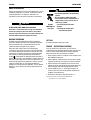
RECOMMENDED COPPER CABLE SIZES
Cables Sizes for Combined Length
of Electrode Plus Work Cable
Amps Duty Cycle Up to 200ft.(61m) 200 to 250ft.
(61 to 76m)
250 100% 1 1/0
300 60% 1/0 2/0
400 35% 3/0 4/0
VEHICLE MOUNTING
I
mproperly mounted concentrated loads may cause unstable
vehicle handling and tires or other components to fail.
• Only transport this Equipment on serviceable vehicles
w
hich are rated and designed for such loads.
• Distribute, balance and secure loads so vehicle is stable
under conditions of use.
• Do not exceed maximum rated loads for components
such as suspension, axles and tires.
• Use appropriate nuts bolts and lockwashers to attach the
equipment base to the metal bed or frame of vehicle.
• Follow vehicle manufacturer’s instructions.
• Stop engine while fueling.
• Do not smoke when fueling.
• Keep sparks and flame away from tank.
• Do not leave unattended while fueling.
• Wipe up spilled fuel and allow fumes to
clear before starting engine.
• Do not overfill tank, fuel expansion may
cause overflow.
DIESEL FUEL ONLY-Low sulphur fuel or
ultra low sulphur fuel in U.S.A. and
Canada.
DIESEL FUEL
can
cause fire
CAUTION
WARNING
WARNING

A-6
INSTALLATIONSA-400I
®
BATTERY CHARGING
The SA-400I
®
is equipped with a wet charged battery. The
charging current is automatically regulated when the battery is
low (after starting the engine) to a trickle current when the bat-
tery is fully charged.
When replacing, jumping or otherwise connecting the battery to
the battery cables, the proper polarity must be observed. This
system is NEGATIVE GROUND.
GASES FROM BATTERY can explode.
•
Keep sparks, flame and cigarettes away.
BATTERY ACID can burn eyes and skin.
• Wear gloves and eye protection and be
careful when boosting, charging or work-
ing near battery.
To prevent EXPLOSION when:
a) Installing a new battery - disconnect thenegative cable
from the old battery first and connect the negative cable
to the new battery last.
b) Connecting a battery charger - remove the battery from
the welder by disconnecting the negative cable first, then
the positive cable and battery clamp. When reinstalling,
connect the negative cable last.
c) Using a booster - connect the positive lead to the battery
first, then connect the negative lead to the ground lead on
the base.
To prevent ELECTRICAL DAMAGE when:
a) Installing a new battery.
b) Using a booster.
Use correct polarity - Negative Ground.
To prevent BATTERY DISCHARGE, if you have an ignition
switch, turn it off when engine is not running.
• To prevent BATTERY BUCKLING, tighten nuts on battery
clamp until snug.
WARNING

A-7
INSTALLATIONSA-400I
®
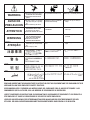
Certain Electrical devices cannot be powered to this Product. See Table A.1
TABLE A.1
E
LECTRICAL DEVICE USE WITH THIS PRODUCT
Type
Resistive
Capacitive
Inductive
Capacitive / Inductive
Common Electrical Devices
Heaters, toasters, incandescent
light bulbs, electric range, hot
pan, skillet, coffee maker.
TV sets, radios, microwaves,
appliances with electrical control.
Single-phase induction motors,
drills, well pumps, grinders, small
refrigerators, weed and hedge
trimmers.
Computers, high resolution TV sets,
complicated electrical equipment.
Possible Concerns
NONE
Voltage spikes or high voltage
regulation can cause the capac-
itative elements to fail. Surge
protection, transient protection,
and additional loading is recom-
mended for 100% fail-safe
operation. DO NOT RUN
THESE DEVICES WITHOUT
ADDITIONAL RESISTIVE TYPE
LOADS.
These devices require large
current inrush for starting.
Some synchronous motors may
be frequency sensitive to attain
maximum output torque, but
they SHOULD BE SAFE from
any frequency induced failures.
An inductive type line condition-
er along with transient and
surge protection is required,
and liabilities still exist.
DO NOT USE THESE DEVICES
WITH THIS PRODUCT.
The Lincoln Electric Company is not responsible for any damage to electrical components
improperly connected to this product.
CAUTION

ENGINE OPERATION
Operate the welder with the doors closed. Leaving the doors
open changes the designed air flow and can cause overheating.
STARTING THE SA-400I
®
PERKINS 404D-22
DIESEL ENGINE
1. Turn the “IDLER” switch to “HIGH”.
2. Turn the “IGNITION” switch to “ON”.
3. Press the Glow Plug button for 20 to 30 seconds.
(maximum 60 seconds).
4. Press the Start button. When the engine starts running,
release both buttons. If the engine fails to start in 20
seconds, wait 30 seconds and repeat the above
procedure.
5. Observe the oil pressure. If no pressure shows within
30 seconds, stop the engine and consult the engine
operating manual. To stop the engine, turn the
“IGNITION” switch to “OFF”.
6. If the engine protection warning light comes on during
cranking or after start up, the “IGNITION” switch must
be turned “OFF” to reset the engine protection system.
7. Allow the engine to run at high idle speed for several
minutes to warm the engine. Stop the engine and
recheck the oil level, after allowing sufficient time for
the oil to drain into the pan. If the level is down, fill it to
the full mark again. The engine controls were properly
set at the factory and should require no adjusting when
received.
Do not attempt to use this equipment until you have thor-
o
ughly read the engine manufacturer’s manual supplied
with your welder. It includes important safety precautions,
detailed engine starting, operating and maintenance
instructions, and parts lists.
ELECTRIC SHOCK can kill.
• Do not touch electrically live parts or elec-
trode with skin or wet clothing.
• Insulate yourself from work and ground
• Always wear dry insulating gloves.
ENGINE EXHAUST can kill.
• Use in open, well ventilated areas or vent
exhaust outside.
MOVING PARTS can injure.
• Do not operate with doors open or guards off.
• Stop engine before servicing.
• Keep away from moving parts.
See additional warning information at
the front of this operator’s manual.
C
OLD WEATHER STARTING:
W
ith a fully charged battery and the proper weight oil, the engine
should start satisfactorily even down to about -15°F (-26°C), it
maybe desirable to install cold-starting aides.
Note: Extreme cold weather starting may require longer glow
plug operation.
Under NO
conditions should ether or other starting fluids
be used!
HIGH ALTITUDE OPERATION:
The engine will run correctly up to an altitude of 600 meters
(12,000 ft.). If the engine is to be operated permanently at an
altitude above this, the fuel consumption and exhaust emissions
may be excessive.
Contact a Perkins Service Representative for any engine
adjustments that may be required.
STOPPING THE ENGINE
1. Turn the “IGNITION” switch to “OFF”
At the end of each day’s welding, check the crankcase oil level,
drain accumulated dirt and water from the water separator
located on the fuel rail. Refill the fuel tank to minimize moisture
condensation in the tank. Also, running out of fuel tends to draw
dirt into the fuel system.
When hauling the welder between job sites, close the fuel feed
valve on the separator located on the fuel rail.
If the fuel supply is cut off or runs out while the fuel pump is
operating, air may be entrapped in the fuel distribution system. If
this happens, bleeding of the fuel system may be necessary. Use
qualified personnel to do this per the instructions in the
MAINTENANCE section of this manual.
WARNING
WARNING
B-1
OPERATION
SA-400I
®

B-2
OPERATION
SA-400I
®
Some arc instability may be experienced with EXX10 electrodes
when trying to operate with long arc techniques at settings at the
lower end of the open circuit voltage range.
DO NOT attempt to set the “Current Range Selector” between the
five points designated on the nameplate.
-----------------------------------------------------------------
These switches have a spring loaded cam which almost elimi-
nates the possibility of setting this switch between the designat-
ed points.
ENGINE BREAK-IN
Lincoln Electric selects high quality, heavy-duty industrial
engines for the portable welding machines we offer. While it is
normal to see a small amount of crankcase oil consumption
during initial operation, excessive oil use, wet stacking (oil or tar
l
ike substance at the exhaust port), or excessive smoke is not
normal.
Larger machines with a capacity of 350 amperes and higher,
which are operated at low or no-load conditions for extended
periods of time are especially susceptible to the conditions
described above. To accomplish successful engine break-in,
most diesel-powered equipment needs only to be run at a
reasonably heavy load within the rating of the welder for some
period of time during the engine’s early life. However, if the
welder is subjected to extensive light loading, occasional
moderate to heavy loading of the engine may sometimes be
necessary. Caution must be observed in correctly loading a
diesel/generator unit.
1. Connect the welder output studs to a suitable resistive load
bank. Note that any attempt to short the output studs by
connecting the welding leads together, direct shorting of the
output studs, or connecting the output leads to a length of
steel will result in catastrophic damage to the generator and
voids the warranty.
2. Set the welder controls for an output current and voltage
within the welder rating and duty cycle. Note that any
attempt to exceed the welder rating or duty cycle for any
period of time will result in catastrophic damage to the
generator and voids the warranty.
3. Periodically shut off the engine and check the crankcase oil
level.
WELDER OPERATION
DUTY CYCLE
T
he NEMA output rating of the SA-400I
®
i
s 300 amperes at 32
arc volts on a 60% duty cycle (consult Specifications in this
manual for alternate ratings). Duty cycle is based on a ten
minute period; thus, the welder can be loaded at rated output for
s
ix minutes out of every ten minute period.
CONTROL OF WELDING CURRENT
DO NOT TURN THE “CURRENT RANGE SELECTOR” WHILE
WELDING because the current may arc between the contacts
and damage the switch.
-----------------------------------------------------------------
The “Current Range Selector” provides five overlapping current
ranges. The “Fine Current Adjustment” adjusts the current from
minimum to maximum within each range. Open circuit voltage
is also controlled by the “Fine Current Adjustment” permitting
control of the arc characteristics.
A high open circuit voltage setting provides the soft “buttering”
arc with best resistance to pop-outs preferred for most welding.
To get this characteristic, set the “Current Range Selector” to the
lowest setting that still provides the current you need and set the
“Fine Current Adjustment” near maximum.
For example: to obtain 180 amps and a soft arc, set the
“Current Range Selector” to the 190-120 position and then
adjust the “Fine Current Adjustment” for 180 amps.
When a forceful “digging” arc is required, usually for vertical and
overhead welding, use a higher “Current Range Selector” setting
and lower open circuit voltage.
For example: to obtain 180 amps and a forceful arc, set the
“Current Range Selector” to the 260-170 position and the “Fine
Current Adjustment” setting to get 180 amps.
ELECTRIC SHOCK can kill.
• Do not touch electrically live parts or
electrode with skin or wet clothing.
• Insulate yourself from work and ground.
FUMES & GASES can be dangerous.
• Keep your head out of the fumes.
• Use ventilation or exhaust to remove
fumes from breathing zone.
WELDING SPARKS can cause fire or explosion.
• Keep flammable material away.
ARC RAYS can burn.
• Wear eye, ear, and body protection.
WARNING
CAUTION
CAUTION

B-3
OPERATION
SA-400I
®
AUXILIARY POWER
If GFCI is tripped, See the MAINTENANCE section for detailed
information on testing and resetting the GFCI.
The AC auxiliary power, supplied as a standard, has a rating of
3
.0 KVA of 120/240 VAC (60 hertz). Set fine current adjustment
at 100 for maximum auxiliary power.
With the 3.0 KVA, 120/240 VAC auxiliary power, one 120V duplex
protected by GFCI and one 240V duplex, grounding type
receptacle with 2 pole, 15 amp circuit breaker.
One 240 VAC European (IEC-309) 16 AMP receptacle is protected
by a 15 AMP 2-pole circuit breaker, that provides 3.0 KVA of
continuous power. Maximum current is 15 AMPs (only on code
12459).
The rating of 3.0 KVA permits a maximum continuous current of
13 amps to be drawn from the 240V duplex receptacle. 20 amps
can be drawn from the 120V duplex receptacle. The total
combined load of all receptacles is not to exceed 3.0 KVA.
An optional power plug kit is available. When this kit is specified,
the customer is supplied with a plug for each receptacle.
IDLER OPERATION
Start the engine with the “Idler” switch in the “High” position.
Allow it to run at high idle speed for several minutes to warm the
engine. See Specifications for operating speeds.
The idler is controlled by the “Idler” toggle switch on the welder
c
ontrol panel. The switch has two positions as follows:
1. In the “High” position, the idler solenoid deactivates,
a
nd the engine goes to high idle speed. The speed is con-
trolled by the governor.
2. In the “Auto” / position, the idler operates as fol-
lows:
a. When welding or drawing power for lights or tools (approxi-
mately 100 watts minimum) from the receptacles, the idler
solenoid deactivates and the engine operates at high idle
speed.
b. When welding ceases or the power load is turned off, a pre-
set time delay of about 15 seconds starts. This time delay
cannot be adjusted.
c. If the welding or power load is not re-started before the end
of the time delay, the idler solenoid activates and reduces
the engine to low idle speed.
RESIDUAL CURRENT DEVICE READY (ONLY FOR 12459)
The SA-400I is configured to allow for the addition of a Residual
Current Device (RCD) to protect the 240V Single Phase
Receptacle. The auxiliary power area on the front panel of the
SA-400I has a hole sized and shaped to accept a typical 2-pole
(RCD) along with a protective rubber boot. A cover plate with a
label “RCD Ready” covers the hole and secures a mounting
bracket on the backside of the panel.
NOTE: the RCD should be rated for at least 15 amps. There are
many suppliers of RCDs. Some examples are:
• Allen Bradley, part number 1492-RCD2A40
• Clipsal, part number 4RC225/30
The protective boot can be used on both RCDs & can be
obtained from:
• APM-Hexseal, part number HE-1035
See Section F-3 Diagrams of this Operator’s Manual for
instructions on installing an RCD and protective rubber boot.
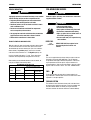
SA-400I
®
WITH PERKINS 404D-22 DIESEL ENGINE TYPICAL FUEL CONSUMPTION DATA
Low Idle -No Load
High Idle -No Load
3000 Watts
250 Amps @ 30 Volts
300 Amps @ 32 Volts
400 Amps @ 25 Volts
0.31 gal/hr ( 1.17 ltrs/hr)
0.45 gal/hr ( 1.70 ltrs/hr)
0.59 gal/hr ( 2.23 ltrs/hr)
1.00 gal/hr ( 3.79 ltrs/hr)
1.21 gal/hr ( 4.60 ltrs/hr)
1.36 gal/hr ( 5.14 ltrs/hr)

OPTIONAL FEATURES (Field Installed)
GENERAL OPTIONS
Pipe Thawing with an arc welder can cause fire, explosion,
damage to electric wiring or to the arc welder if done
improperly. The use of an arc welder for pipe thawing is not
approved by the CSA, nor is it recommended or supported
by Lincoln Electric.
FIELD INSTALLED OPTIONAL ACCESSORIES
Follow these steps:
1. Go to www.lincolnelectric.com.
2. At the top of the screen in the Search field type E6.162 click
on Search icon.
3. On the results screen click on SA-400I
®
product information.
4. On the results screen which shows SA-400I
®
sales literature
document, scroll down the beginning of the RECOMMENDED
OPTIONS page.
WARNING
C-1
ACCESSORIES
SA-400I
®

SAFETY PRECAUTIONS
GENERAL INSTRUCTIONS
1. Blow out the welder and controls with an air hose at least
once every two months. In particularly dirty locations, this
cleaning may be necessary once a week. Use low pressure
air to avoid driving dirt into the insulation.
2. Follow the engine service schedule in this manual and the
detailed maintenance and troubleshooting in the engine
manufacturer’s manual.
COOLING SYSTEM
The SA-400I® is equipped with a pressure radiator. Keep the
r
adiator cap tight to prevent loss of coolant. Clean and flush the
cooling system periodically to prevent clogging the passage and
overheating the engine. When antifreeze is needed, always use
the permanent type.
BEARINGS
This welder is equipped with a double synthetic sealed ball
bearing having sufficient grease to last indefinitely under normal
service.
COMMUTATOR AND BRUSHES
Uncovered rotating equipment can be dangerous. Use care
so your hands, hair, clothing or tools do not catch in the
rotating parts. Protect yourself from particles that may be
thrown out by the rotating armature when stoning the com-
mutator.
Shifting of the commutator brushes may result in:
- Change in machine output
- Commutator damage
- Excessive brush wear
Periodically inspect the commutator, slip rings, and brushes by
removing the covers. DO NOT remove or replace these covers
while the machine is running. Commutators and slip rings
require little attention. However, if they are black or appear
uneven, have them cleaned by an experienced maintenance man
using fine sandpaper or a commutator stone. Never use emery
cloth or paper for this purpose.
IDLER MAINTENANCE
Before doing electrical work on the idler printed circuit
board, disconnect the battery.
-----------------------------------------------------------------
When installing a new battery or using a jumper battery to start
the engine, be sure the battery polarity is connected properly.
The correct polarity is negative ground. Damage to the engine
alternator and the printed circuit board can result from incorrect
connection.
1. Proper operation of the idler requires good grounding of the
printed circuit board, reed switch, and battery.
2. Idler solenoid is activated for low idle.
3. If desired, the welder can be used without automatic idling by
setting the “Idler” switch to the “High” position.
Have qualified personnel do the maintenance work. Turn
the engine off before working inside the machine. In some
c
ases, it may be necessary to remove safety guards to
perform required maintenance. Remove guards only when
necessary and replace them when the maintenance
requiring their removal is complete. Always use the great-
est care when working near moving parts.
Do not put your hands near the engine cooling blower fan.
If a problem cannot be corrected by following the instruc-
tions, take the machine to the nearest Lincoln Field
Service Shop.
ELECTRIC SHOCK can kill.
• Do not touch electrically live parts or elec-
trode with skin or wet clothing.
• Insulate yourself from work and ground
• Always wear dry insulating gloves.
ENGINE EXHAUST can kill.
• Use in open, well ventilated areas or vent
exhaust outside.
MOVING PARTS can injure.
• Do not operate with doors open or guards
off.
• Stop engine before servicing.
• Keep away from moving parts.
See additional warning information at front of this
operator’s manual.
WARNING
WARNING
CAUTION
D-1
MAINTENANCE
SA-400I
®
La page est en cours de chargement...
La page est en cours de chargement...
La page est en cours de chargement...
La page est en cours de chargement...
La page est en cours de chargement...
La page est en cours de chargement...
La page est en cours de chargement...
La page est en cours de chargement...
La page est en cours de chargement...
La page est en cours de chargement...
La page est en cours de chargement...
La page est en cours de chargement...
La page est en cours de chargement...
La page est en cours de chargement...
La page est en cours de chargement...
La page est en cours de chargement...
La page est en cours de chargement...
La page est en cours de chargement...
La page est en cours de chargement...
La page est en cours de chargement...
La page est en cours de chargement...
La page est en cours de chargement...
La page est en cours de chargement...
La page est en cours de chargement...
La page est en cours de chargement...
La page est en cours de chargement...
La page est en cours de chargement...
La page est en cours de chargement...
La page est en cours de chargement...
La page est en cours de chargement...
La page est en cours de chargement...
La page est en cours de chargement...
La page est en cours de chargement...
La page est en cours de chargement...
La page est en cours de chargement...
La page est en cours de chargement...
La page est en cours de chargement...
La page est en cours de chargement...
La page est en cours de chargement...
La page est en cours de chargement...
La page est en cours de chargement...
La page est en cours de chargement...
La page est en cours de chargement...
La page est en cours de chargement...
La page est en cours de chargement...
La page est en cours de chargement...
La page est en cours de chargement...
La page est en cours de chargement...
-
 1
1
-
 2
2
-
 3
3
-
 4
4
-
 5
5
-
 6
6
-
 7
7
-
 8
8
-
 9
9
-
 10
10
-
 11
11
-
 12
12
-
 13
13
-
 14
14
-
 15
15
-
 16
16
-
 17
17
-
 18
18
-
 19
19
-
 20
20
-
 21
21
-
 22
22
-
 23
23
-
 24
24
-
 25
25
-
 26
26
-
 27
27
-
 28
28
-
 29
29
-
 30
30
-
 31
31
-
 32
32
-
 33
33
-
 34
34
-
 35
35
-
 36
36
-
 37
37
-
 38
38
-
 39
39
-
 40
40
-
 41
41
-
 42
42
-
 43
43
-
 44
44
-
 45
45
-
 46
46
-
 47
47
-
 48
48
-
 49
49
-
 50
50
-
 51
51
-
 52
52
-
 53
53
-
 54
54
-
 55
55
-
 56
56
-
 57
57
-
 58
58
-
 59
59
-
 60
60
-
 61
61
-
 62
62
-
 63
63
-
 64
64
-
 65
65
-
 66
66
-
 67
67
-
 68
68


Lincoln Electric SA-400I Mode d'emploi
- Catégorie
- Système de soudage
- Taper
- Mode d'emploi
dans d''autres langues
Documents connexes
-
Lincoln Electric SA-250 Mode d'emploi
-
-
-
-
Lincoln Electric Ranger 305D Mode d'emploi
-
-
-
-
-