La page est en cours de chargement...

2B, Zao Fong Universe Building, No. 1800 Zhong Shan West Road, Shanghai 200233, China
Phone +86 21 6440 3055, Fax +86 21 6440 3077
www.rotronic.cn
Grindelstrasse 6, CH-8303 Bassersdorf,
Telefon +41 44 838 11 11, Fax +41 44 837 00 73
www.rotronic.com
messgeräte gmbh
Einsteinstrasse 17-23, D-76275 Ettlingen
Telefon +49 7243 383 250, Fax +49 7243 383 260
www.rotronic.de
56, Bld.de Courcerin, Bât 43, F-77183 Croissy Beaubourg
Tél. +33 1 60 95 07 10, Fax +33 1 60 17 12 56
www.rotronic.fr
Unit1A Crompton Fields, Manor Royal, Crawley, West Sussex RH10 9EE
Phone +44 1293 57 10 00, Fax +44 1293-57 10 08
www.rotronic.co.uk
160, East Main Street, Huntington N.Y. 11743 USA
Phone +1 631 427 38 98, Fax +1 631 427 39 02
www.rotronic-usa.com
Specifications
Supply voltage: 12...35 VDC or 12…24 VAC,
max. 200 mA or
90…264 VAC 50/60 Hz
Operating range: 0…99 %rF (non condensing)
– 40...60 °C
Interface: RS485, 5pin connector Binder 723 female
Digital inputs: 2
Relay contacts: 4 x single pole double throw (SPDT)
Contact rating: 10 A @ 250 VAC or 30 VDC,
12 A @125 VAC
Electrical connections: Cable grips and terminals
1)
Housing Material: ABS
Housing Dimensions: 160 x 120 x 75 mm
Weight: 800 g
IP-rating: IP65 / NEMA 4
1)
Recommended cable for cable grips:
7..9 mm diameter (0.275..0.354”) with 18 AWG wires.
We congratulate you on the purchase of your new ROTRONIC HygroClip Alarm
card. You have thus acquired a device corresponding to the latest state of the
art. Please read these short instructions carefully before you install the device.
This short operating instruction manual is restricted to the description of the
main functions of the device. A full version of the operating manual may be
downloaded from the internet under:
www.rotronic.ch/link/manual
Factory default programming
The basic settings of the devices are made in the factory according to your order.
They can be changed by the user by using the ROTRONIC HW4 software.
Electrical connections
The instruments are supplied with 12...35 VDC/12...24 VAC or with 90...264 VAC.
The supply tension of your device is mentioned on the instrument label.
Caution:
Wrong supply tension may damage the transmitter!
General description
The HYGROCLIP ALARM is a configurable alarm card with 4 independent re
-
lay contacts and is primarily designed for use with the networkable Rotronic
HygroClip humidity-temperature instruments. The HYGROCLIP ALARM can be
used to turn on and off a variety of devices such as a humidifier or a dehumidifier,
a heater or a cooling coil, a siren, etc.
The RS485 port of the HYGROCLIP ALARM is used to establish a connection
with the network and to monitor the measurements of selected instruments and
probes on the network. In addition to the RS485 port, the HYGROCLIP ALARM has
also two digital inputs (logical one or zero) which can be used for example to
monitor the status of up to two electrical contacts (door closed or open, etc.).
The HYGROCLIP ALARM has 4 independent, programmable single pole double
throw (SPDT) relay contacts. Each contact can be associated with any one of
the parameters measured by the instruments and probes on the network. The
association of a relay contact with a parameter is done by configuring the internal
programmable logic of the HYGROCLIP ALARM. For programming purposes, the
HYGROCLIP ALARM offers a large choice of virtual components such as gates,
delays, real time alarms, etc. If so desired, the HYGROCLIP ALARM allows a
total of up to 128 measured parameters to be associated with a single relay
contact by combining the parameters with the AND or the OR logical function.
It is also possible to associate a relay contact with one or both digital inputs of
the HYGROCLIP ALARM.
The HYGROCLIP ALARM can be located anywhere on the network, in the same
manner as any other networkable instrument from Rotronic. If so desired, several
alarm cards can be used on the network, as long as each one has a different
network address.
To make use of all the features of the HYGROCLIP ALARM, such as the logging
of events to a disk file, the HYGROCLIP ALARM is best used on a network driven
by a PC on which the Rotronic HW4 software has been installed. The Windows
based HW4 software is required to configure / program the HYGROCLIP ALARM
and it minimizes the amount of time required to set up the network. In principle,
the HYGROCLIP ALARM can also be used with a non - Windows based computer
but this requires additional programming by the user.
The HYGROCLIP ALARM can be used without a PC when it has been configured
with HW4 to automatically interrogate the instruments and probes on the net
-
work. The internal memory of the HYGROCLIP ALARM retains the most recent 20
events and can be read later on with a PC. In the simplest case, the HYGROCLIP
ALARM is used with a single instrument and is directly connected to the RS485
port of that instrument.
Main Features
- monitoring of up to 4 measured parameters such as humidity or temperature
- Calculates and monitors the dew point corresponding to the humidity and
temperature measured by any probe on the network
- monitoring of up to 128 parameters globally combined (AND or OR logical
function)
- two digital inputs for monitoring up to two electrical contacts
- four programmable relay contacts, each with its own status LED
- internal programmable logic comprised of the following configurable elements:
- 12 x delay
- 6 x flip-flop
- 12 x gate
- 2 x monoflop
- 1 x PWM (pulse width modulator)
- 2 x real time alarm
- 4 x virtual key (simulated push button switch)
- internal clock with battery for the date stamping of events
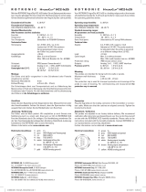
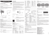
Electrical Connections
Pinning / connections
Supply: 1: AC Neutral or DC –
2: AC Phase or DC +
3: Ground /protective ground
Input 1 & 2: GND: Ground – provides logical 0 when connected to IN
IN: logical input
+3.5V: provides logical 1 when connected to IN
Relay Out: (1 to 4)
NC: normally closed (relay is not energized)
COM: common
NO: normally open (relay not energized)
All connections with the exception of the RS485 signal are present on screw
terminals, while the RS485 signal is available on a Binder 5-pin female con-
nector.
RS485: 1 not used
2 not used
3 GND
4 RI +
5 RI –
RS485 port and networking
The RS485 port is used to connect the HYGROCLIP ALARM to a network consti-
tuted of networkable ROTRONIC HygroClip humidity-temperature instruments.
Connection to the network, or to a single instrument, requires two wires: RI +
and RI -. Be sure to observe the polarity of the RS485 connection.
HygroClip Alarm-4
The devices may be supplied via the RS48 cable. Do not connect the normal
supply terminals in this case. If the devices are powered via the RS485 multi
drop network cable, the cable should be run through one of the cable glands
directly to the terminal block
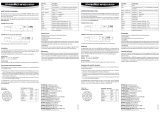
Up to 64 instruments, including any alarm card(s), can be connected together
on a network. The master (unit 0) is always the unit that is directly connected
to the PC. Since the HYGROCLIP ALARM features only an RS485 port, it cannot
be the master unit. Some planning is required before establishing the network
since each unit on the network must be given a unique network address with
the HW4 software (0 to 63). For detailed instructions, see the full version manual,
which can be downloaded from www.rotronic.ch/link/manual.
For wiring please refer to the usual installation guidelines as well as the instal
-
lation instruction for networkable ROTRONIC devices, that are contained in the
full version of the manual too.
Networking Schematic
Wiring in zones with possible electromagnetic interferences
As a rule, signal cables should be separated from othe cables according to th
etable below:
Lightning protection
Cabling in areas endangered by lightning requires a lightning protection. For
cabling between different buildings in the ground, we recommend the use of
special cabling. If this is not possible, use copper cables that are suitable for
laying in the earth.
PC
COM
RS232 (3 wires)
max. 12 m
2-cables
connector
2 wires
RS485 (2 wires, max. 1000 m
Device 0 Device 1 Device 63
(Master)
These signal cables may
lie in common bundles
or cable channels, but
separated from the other
types below.
These signal cables may
lie in separated bundles
or cable channels, but
separated from the other
types.
These signal cables may
lie in separated bundles
or cable channels, but
separated from the other
types.
- Bus signals such as RS485
- Data signals for PC´s, PG´s , printers etc.
- shielded analogue inputs
- unshielded direct current (≤ 60V)
- shielded process signals (≤ 25 V)
- unshielded alternate current (≤ 25V)
- coaxial cables for CRT monitors
- direct current from 60 V to 400 V
(unshielded)
- alternate current from 25V to 400 V
(unshielded)
- direct and alternate current > 400 V
(unshielded)
- Telephone lines
- lines that are leading into EX-rated areas
A
12.0747.0003
12
3
4
5
Networkable
Alarmcard
Instruction Manual
Relais Out 2
Relais Out 1
Relais Out 3
Relais Out 4
1
2
3
1 2 3
1 2 3
1 2 3
1 2 3
Supply
RS485
GND
IN1
+3.5 V
GND
IN2
+3.5 V
VDC+
GND
RI+
RI-
LED
Power Supply
Module

2B, Zao Fong Universe Building, No. 1800 Zhong Shan West Road, Shanghai 200233, China
Phone +86 21 6440 3055, Fax +86 21 6440 3077
www.rotronic.cn
Grindelstrasse 6, CH-8303 Bassersdorf,
Telefon +41 44 838 11 11, Fax +41 44 837 00 73
www.rotronic.com
messgeräte gmbh
Einsteinstrasse 17-23, D-76275 Ettlingen
Telefon +49 7243 383 250, Fax +49 7243 383 260
www.rotronic.de
56, Bld.de Courcerin, Bât 43, F-77183 Croissy Beaubourg
Tél. +33 1 60 95 07 10, Fax +33 1 60 17 12 56
www.rotronic.fr
Unit1A Crompton Fields, Manor Royal, Crawley, West Sussex RH10 9EE
Phone +44 1293 57 10 00, Fax +44 1293-57 10 08
www.rotronic.co.uk
160, East Main Street, Huntington N.Y. 11743 USA
Phone +1 631 427 38 98, Fax +1 631 427 39 02
www.rotronic-usa.com
Spécifications
Tension d’alimentation: 12…35 VCC ou 12…24 VCA max 200 mA
ou 90…264 VAC 50/60 Hz
Plage d’utilisation: 0…99 % HR (sans condensation), -40 à +60°C
Interface: RS485 , connecteur Binder 5 broches 723 femelle
Entrées numériques: 2
Contacts relais: 4 x SPDT
Contact: 10 A @ 250 VCA ou 30 VCC
12 A @ 125 VCA
Connexions électriques: presse étoupes et borniers
1)
Boîtier: ABS
Dimensions boîtier: 160 x 120 x 75 mm
Poids: 800 g
Protection: IP65 / NEMA 4
1)
Câbles recommandés pour presse é toupes:
7..9 mm de diamétre (0.275..0.354”) avec 18 AWG fils.
Alarm pour réseau
Manuel d’utilisation
Nous vous félicitons d’avoir choisi le nouveau Hygroclip Alarm ROTRONIC, doté
de la technologie la plus récente pour ce type d’appareil. Nous vous remercions
de lire ce mode d’emploi avant d’installer votre instrument.
Ce mode d’emploi se limite à la description des fonctions essentielles de ce
transmetteur. Vous trouverez une notice détaillée sur notre site internet::
www.rotronic.ch/link/manual
Programmation usine par défaut
Les réglages standard de cet instrument sont fait en usine. La configuration peut
être modifiée par l’utilisateur grâce au logiciel ROTRONIC HW4 (option).
Raccordement électriques
Les Hygroclip Alarm peuvent être alimentés en 12…35 VCC/12…24 VCA ou
90…264 VCA. Il est indispensable de vérifier la tension d’alimentation de votre
appareil sur la plaque signalétique avant de le raccorder.
Attention :
Une tension d’alimentation non appropriée peut causer des dom-
mages à votre appareil
Description générale
Le Hygroclip Alarm est une alarme configurable avec 4 relais de contacts
indépendants. Ce dispositif est conçu pour l’utilisation en réseau avec des
instruments de mesure de température et humidité ROTRONIC. Le Hygroclip
Alarm peut être utilisé pour déclencher ou arrêter toute une catégorie d’appareils
tels que par ex humidificateurs, déshumidificateurs, résistance, serpentin de
refroidissement, alarme sonore, etc..
La sortie RS485 de l’Hygroclip Alarm est utilisée pour établir une connexion avec
le réseau et pour la surveillance d’instruments et sondes sélectionnés sur le
réseau. De plus, l’Hygroclip Alarm possède également 2 entrées numériques
(logique 1 ou 0) qui peuvent être utilisées par exemple pour surveiller l’état de
2 contacts électriques (porte ouverte ou fermée, etc).
Le Hygroclip Alarm possède 4 relais de contacts indépendants et programmables
type SPDT. Chaque contact peut être associé avec n’importe quel paramètre
mesuré par le transmetteur et les sondes sur le réseau. L’association d’un contact
avec un paramètre en utilisant les fonctions logiques internes de l’Hygroclip
Alarm. Hygroclip Alarm offre un large choix de composants virtuels tels que
des portes logiques, temporisations, alarmes en temps réel, etc. Jusqu’à 128
paramètres mesurés peuvent être associés avec un seul contact relais en
combinant les paramètres avec les fonctions logiques “AND” , “OR”. Il est éga
-
lement possible d’associer un relais avec une ou les deux entrées numériques
de l’Hygroclip Alarm.
Hygroclip Alarm peut être placé n’importe où sur le réseau, comme n’importe
quel autre appareil ROTRONIC pouvant être mis en réseau. Si vous le souhaitez
plusieurs Hygroclip Alarm peuvent être mis sur le réseau dans la mesure où ils
ont des adresses différentes.
Pour utiliser toutes les fonctions de Hygroclip Alarm comme enregistrement
d’événements sur un fichier, il est préférable d’utiliser Hygroclip Alarm sur un ré
-
seau piloté par un PC sur lequel HW4 est installé. Le logiciel HW4 sous Windows
est nécessaire pour configurer / programmer Hygroclip Alarm et cela minimise
le temps nécessaire pour la configuration du réseau. Il est également possible
d’utiliser Hygroroclip Alarm hors environnement Windows mais l’utilisateur devra
prévoir une programmation spécifique.
Hygroclip Alarm peut être utilisé sans PC lorsqu’il a été configuré au préalable
par HW4 pour interroger automatiquement les transmetteurs et sondes sur le
réseau. La mémoire interne de Hygroclip Alarm mémorise les 20 derniers évé
-
nements et peut être lue ultérieurement en le raccordant au PC. Dans le cas le
plus simple Hygroclip Alarm est utilisé avec un seul instrument et est raccordé
directement au port RS485 de cet appareil.
Fonctions principales
- Monitoring de 4 paramètres mesurés tels que humidité ou température.
- Calcule et contrôle le point de rosée correspondant à l’humidité et la
température mesurée par n’importe quelle sonde du réseau
- Surveillance de 128 paramètres combinés au maximum (fonctions
logiques AND /OR)
- 2 entrées numériques pour contrôler deux contacts électriques
- 4 contacts relais programmables, chacun avec LED d’indication état
- Fonctions logiques internes programmables avec les éléments suivants
configurables :
- 12 temporisations,
- 6 flip-flop
- 12 portes logiques
- 2 monoflop
- 1 modulateur de largeur d’impulsion
- 2 alarmes en temps réel
- 4 touches virtuelles (simulation d’interrupteurs)
- horloge interne avec pile
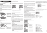
Raccordements électriques
Connexions
Alimentation: 1 Neutre CA ou CC –
2 Phase CA ou CC +
3 Terre
Entrée 1 & 2: GND Terre fourni 0 logique si raccordé à IN
IN Entrée logique
+3.5V Fourni 1 logique si raccordé à IN
Relais Sortie: (1 à 4) NC Normalement fermé (relais pas alimenté)
COM Commun
NO Normalement ouvert (relais pas
alimenté)
Toutes les connexions (sauf signal RS485) sont présents sur les borniers à vis.
Le signal RS485 est disponible sur un connecteur binder 5 pôles femelle.
RS485: 1 Pas utilisé
2 Pas utilisé
3 GND
4 RI +
5 RI –
Port RS485 et réseau
Le port RS485 est utilisé pour connecter le Hygroclip Alarm à un réseau cons-
titué de transmetteurs ROTRONIC Hygroclip pour la mesure de l’humidité et la
température. Le raccordement au réseau ou à un seul instrument nécessite 2
fils : RI + et RI –. Veuillez vérifier la polarité de la connexion RS485.
Il est aussi possible d‘alimenter l‘HygroClip Alarm par le câble RS485. Ne connec-
tez pas les terminaux de l‘alimentation normale. Si les instruments sont alimentés
par le câble de réseau RS485, nous recommandons de faire les connections
directement à travers d’un presse-étoupe sur le bloc des terminaux.
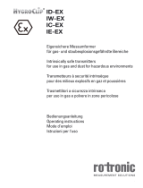
64 instruments maximum, carte(s) d’alarme y compris, peuvent être connectés
ensemble sur un réseau. Le maître (adresse 0) est toujours celui qui est connecté
directement au PC. L‘ Hygroclip Alarm ne peut être maître car il ne possède qu‘un
port RS485. Il est nécessaire de prévoir son installation avant de connecter le
réseau car chaque transmetteur sur le réseau, doit avoir une adresse unique
attribuée par le logiciel HW4. (0 à 64).
Pour des instructions détaillées, veuillez consulter le manuel complet qui peut
être téléchargé sur Internet. www.rotronic.ch/link/manual.
Nous recommandons de respecter les règles habituelles et le guide d’installation
ROTRONIC, mentionnées dans le manuel complet.
Schéma de mise en réseau
Câblage dans des zones où il est possible qu’il y ait des interférences élec-
tromagnétiques
La règle veut que les câbles pour signaux soit séparés les uns des autres suivant
le tableau ci-dessous:
Protection contre la foudre
Les câbles dans des zones risquant de subir la foudre ont besoin d’avoir une
protection contre celle-ci. Pour câbler entre deux bâtiments dans le sol, nous
recommandons d’utiliser un câblage spécialement adapté. Si cela n’est pas
possible, utiliser des câbles en cuivre utilisables pour passage sous terre.
A
PC
COM
RS232 (3 fils) max.
12 m
Connecteur
2 câbles
2 fils
RS485 (2 fils, max. 1000 m
Appareil 0 Appareil 1 Appareil 63
(maître)
Ces câbles de signaux
peuvent être mis dans des
“common bundles” ou
goulottes mais séparés
des autres types ci-des-
sous.
Ces câbles de signaux
peuvent être mis dans des
“common bundles” ou
goulottes mais séparés
des autres types ci-des-
sous.
Ces câbles de signaux
peuvent être mis dans des
“common bundles” ou
goulottes mais séparés
des autres types ci-des-
sous.
- Signaux bus comme RS485
- Signaux de données pour PC, PG,
- imprimantes, etc.
Entrées analogiques isolées
- Courant continu non isolés (
≤ 60 V)
- Signaux de process isolé (≤ 25 V)
- Courant alternatif non isolé (
≤ 25 V)
- Câbles coaxiaux pour écrans CRT
- Courant continu de 60 V à 400 V
(non isolé)
- Courant alternatif de 25 V à 400 V
(non isolé)
- Courant continu ou alternatif > 400 V
(non isolé)
- Lignes téléphoniques
- Lignes vers zone EX
12.0747.0003
12
3
4
5
Relais
Sortie 2
Relais
Sortie 1
Relais
Sortie 3
Relais
Sortie 4
1
2
3
1 2 3
1 2 3
1 2 3
1 2 3
Alimentation
RS485
GND
IN1
+3.5 V
GND
IN2
+3.5 V
VDC+
GND
RI+
RI-
LED
Module
d’alimentation
HygroClip Alarm-4

2B, Zao Fong Universe Building, No. 1800 Zhong Shan West Road, Shanghai 200233, China
Phone +86 21 6440 3055, Fax +86 21 6440 3077
www.rotronic.cn
Grindelstrasse 6, CH-8303 Bassersdorf,
Telefon +41 44 838 11 11, Fax +41 44 837 00 73
www.rotronic.com
messgeräte gmbh
Einsteinstrasse 17-23, D-76275 Ettlingen
Telefon +49 7243 383 250, Fax +49 7243 383 260
www.rotronic.de
56, Bld.de Courcerin, Bât 43, F-77183 Croissy Beaubourg
Tél. +33 1 60 95 07 10, Fax +33 1 60 17 12 56
www.rotronic.fr
Unit1A Crompton Fields, Manor Royal, Crawley, West Sussex RH10 9EE
Phone +44 1293 57 10 00, Fax +44 1293-57 10 08
www.rotronic.co.uk
160, East Main Street, Huntington N.Y. 11743 USA
Phone +1 631 427 38 98, Fax +1 631 427 39 02
www.rotronic-usa.com
Scheda di Allarme per
inserimento in rete
Manuale d’Istruzione
Ci congratuliamo con voi per l’acquisto della vostra nuova scheda ROTRONIC
HygroClip Alarm. Avete acquistato un dispositivo corrispondente alle caratteri
-
stiche fornite dall’ultimo stato dell’arte.
Vi invitiamo a leggere attentamente queste istruzioni prima di installare il dispo
-
sitivo. Questo breve manuale di istruzioni operative è limitato alla descrizione
delle principali funzioni del dispositivo.
Una completa ed esauriente versione del Manuale Operativo può essere sca
-
ricato dal seguente sito internet :
www.rotronic.ch/link/manual
Programmazione di Fabbrica
I dati di configurazione di base del dispositivo sono eseguiti in fabbrica in ac-
cordo con il vostro ordine. Possono essere successivamente modificati usando
il pacchetto software ROTRONIC HW4.
Alimentazioni Elettriche
Gli strumenti sono alimentati con 12 … 36 VDC / 12 … 24 VAC o con 90 … 264
VAC. La tensione di alimentazione del vostro dispositivo è indicata sull’etichetta
dello strumento.
Attenzione:
tensioni di alimentazione errate possono danneggiare il dispositivo!
Descrizione generale
HYGROCLIP ALARM è una scheda di allarme configurabile con 4 contatti di relé
indipendenti ed è progettato per l’impiego con gli strumenti di rete per la misura
di umidità-temperatura ROTRONIC HygroClip. HYGROCLIP ALARM può essere
impiegato per l’accensione e spegnimento di equipaggiamenti quali umidificatori
e deumidificatori, riscaldatori o raffreddatori, sirene etc.
HYGROCLIP ALARM dispone di una porta RS485 per il collegamento in rete e
monitorare le misure di selezionati strumenti e sonde sulla rete. In aggiunta alla
porta RS485, HYGROCLIP ALARM ha due ingressi digitali ( logica uno o zero) che
possono essere utilizzati, per esempio, per monitorare lo stato di due contatti
elettrici (porta chiusa o aperta, etc.).
HYGROCLIP ALARM ha 4 contatti di relè polo singolo doppio scambio (SPDT)
programmabili e indipendenti. Ogni contatto può essere associato con qua-
lunque parametro misurato dagli strumenti e sonde sulla rete. L’associazione di
un contatto di relè con un parametro viene stabilita con la configurazione della
logica programmabile interna di HYGROCLIP ALARM. Per scopi di programma
-
zione, HYGROCLIP ALARM offre una vasta scelta di componenti virtuali quali
porte, ritardi, allarmi in tempo reale etc. Se necessario, HYGROCLIP ALARM
consente fino a un totale di 128 parametri misurati di essere associati con un
singolo contatto di relè combinando i parametri in funzione logica AND o OR.
Inoltre è possibile associare un contatto con uno od entrambi gli ingrassi digitali
di HYGROCLIP ALARM.
HYGROCLIP ALARM può essere ubicato in qualsiasi punto della rete, nello stesso
modo di qualunque altro strumento di rete Rotronic. Se necessario, possono
essere utilizzate sulla rete parecchie schede alarm, ciascuna con un proprio
differente indirizzo di rete.
Per l’utilizzo di tutte le prestazioni di HYGROCLIP ALARM, quali ad esempio la
registrazione degli eventi memorizzati in un file su disco, è preferibile l’impiego
di HYGROCLIP ALARM su una rete pilotata da un PC su cui è installato il
pacchetto software HW3. Per configurare/programmare HYGROCLIP ALARM
è richiesto HW4 basato su S.O. Windows e richiede una minima quantità di
tempo per configurarlo in rete. Per principio, HYGROCLIP ALARM può essere
anche usato con PC senza Windows, ma richiede programmazione aggiuntiva
da parte dell’utilizzatore.
HYGROCLIP ALRM può essere usato senza un PC quando è stato configurato
con HW4 per interrogare sulla rete automaticamente strumenti e sonde. La me-
moria interna di HYGROCLIP ALARM mantiene gli ultimi 20 eventi e può essere
successivamente letto da un PC. Nel caso più semplice, HYGROCLIP ALARM è
impiegato con un singolo strumento ed è direttamente connesso con la porta
RS485 dello strumento.
A
Prestazioni principali
- monitoraggio fina a 4 parametri misurati quali umidità e temperatura
- Calcolo e controllo del punto di rugiada corrispondente all’umidità e
temperatura misurati da una qualunque sonda sulla rete
- monitoraggio fino a 128 parametri globalmente combinati
(funzione logica AND o OR)
- due ingressi digitali per il controllo fino a due contatti elettrici
- quattro contatti di relè programmabili, ognuno con il suo proprio LED di stato
- logica interna programmabile costituita dai seguenti elementi configurabili:
- 12 x ritardi
- 6 x flip-flop (bistabile)
- 12 x porte
- 2 x monoflop (monostabile)
- 1 x PWM
- 2 x allarme tempo reale
- 4 x chiave virtuale (pulsante di commutazione simulato)
- clock interno per la stampa datata degli eventi
Collegamenti elettrici
Pinatura/Connessioni
Alimentazione 1: Neutro AC o DC -
2: Fase AC o DC +
3: Terra/ Protezione di terra
Ingressi 1&2 GND: Terra - fornisce logica 0 quando connesso a IN
IN: ingresso logico
+3,5V: fornisce logia 1 quando connesso a IN
Uscita relè: (1 a 4)
NC: normalmente chiuso (relè non eccitato)
COM: comune
NO: normalmente aperto (relè non eccitato)
Tutte i collegamenti con eccezione del segnale RS485 sono presenti su
morsettiere, mentre il segnale RS485 è disponibile su un connettore femmina
Binder 5 pin:
RS485 1 non usato
2 non usato
3 ND
4 RI +
5 RI –
Porta RS485 e rete
La porta RS485 è usata per connettere la scheda HYGROCLIP ALARM, ad una
rete costituita da strumenti di misura di umidità e temperatura Hygroclip Rotronic,
La connessione alla rete, o ad un singolo strumento, richiede due fili RI+ e RI- .
Assicurarsi di osservare correttamente la polarità della connessione RS485.
L‘alimentazione può essere fornita tramite il cavo RS485. Non collegate i termi-
nali standard quando si utilizza questo metodo. Se gli strumenti sono alimentati
via il cavo RS485, suggeriamo di fare le collegazioni direttemente al blocco dei
terminali, usando una dei ghiandole di cavi.
In ogni singola rete si possono collegare fino a 64 strumenti, schede di allarme
incluse. Il master (unità 0) è sempre l’unità che è connessa direttamente al PC.
HYGROCLIP ALARM non può essere l’unità master, poiché ha solamente una
porta RS485. Prima di stabilire la rete occorre una pianificazione degli indirizzi,
poiché ad ogni unità sulla rete deve essere assegnato, con il software HW4,
un unico indirizzo di rete (da 0 a 64) . Per istruzioni dettagliate, siete pregati di
consultare il manuale completo, che può essere scaricato dal sito Internet:
www.rotronic.ch/link/manual.
Per un corretto collegamento e cablaggio si raccomanda di osservare le regole
di installazionie Rotronic, riportate sul manuale.
Schematizzazione della rete
Fili in zone con possibile interferenza elettromagnetica
Come regola, cavi di segnale devono essere separati dagli altri cavi in accordo
alla tabella seguente:
- Segnali di bus come RS485
- Segnali dati per PC, PG stampanti etc.
- Ingressi analogici schermati
- Corrente continua non schermata (≤ 60V)
- Segnali di processo schermati (≤ 25V)
- Corrente alternata non schermata (≤ 25V)
- Cavi coassiali per monitor CRT
- Corrente continua da 60V a 400V
(non schermato)
- Corrente alternata da 25V a 400V
(nonschermato)
- Corrente continua ed alternata > 400V
(non schermato)
- Linee telefoniche
- Linee che sono lasciate dentro aree EX
(non schermato)
Protezione da fulmini
Cablaggi in aree sotto pericolo di fulmini richiedono una protezione dai fulmini.
Per cablaggi sotto terra tra differenti edifici, raccomandiamo di usare speciali
cablaggi. Se non è possibile, usare cavi di rame che sono adeguati per pose
sotto terra.
Questi cavi di segnale
devono essere legati in
fasci comuni o canali di cavi,
ma separati dagli altri tipi
seguenti.
Questi cavi di segnale
devono essere legati in fasci
separati o canali di cavi, ma
separati dagli altri tipi.
Questi cavi di segnale
devono essere legati in
fasci separti o canali di cavi,
ma separati dagli altri tipi.
Specifiche
Tensione di alimentazione: 12….35 VDC o 12….24 VAC max 200mA o
90….264 VAC 50/60 Hz
Intervallo di lavoro: 0….99 %rF (senza condensa)
-40…60 °C
Interfaccia: RS485, connettore femmina a 5 pin Binder 723
Ingressi digitali: 2
Contatti di relè: 4 x polo singolo doppio scambio(SPDT)
Portata contatto: 10 @ 250VAC or 30 VDC
12 @ 125 VAC
Connessioni elettriche: Serra cavi e terminali
1)
Involucro: ABS
Dimensioni del contenitore: 160x120x75 mm
IP-rating: IP65/NEMA 4
1)
Cavo raccomandato per serra cavi:
diametro 7..9 mm (0,275…0,354’) con fili 18 AWG.
12.0747.0003
PC
COM
RS232 (3 fili)
max. 12 m
Connettore
2 fili
2 fili
RS485 (2 fili, max. 1000 m
Scheda 0 Scheda 1 Scheda 63
(master)
12
3
4
5
HygroClip Alarm-4
Relé
Uscita 2
Relé
Uscita 1
Relé
Uscita 3
Relé
Uscita 4
1
2
3
1 2 3
1 2 3
1 2 3
1 2 3
Alimentazione
RS485
GND
IN1
+3.5 V
GND
IN2
+3.5 V
VDC+
GND
RI+
RI-
LED
Modulo
di alimentazione
/