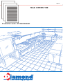
Diamond GY60E Instructions For Assembly, Use And Maintenance
- Taper
- Instructions For Assembly, Use And Maintenance

The catering program
Production code: GY-INO10E-9841
Mod: GYROS 10E
10/2005

I
MANUALE PER L’INSTALLAZIONE, L’USO
E LA MANUTENZIONE DEI
GYROS ELETTRICI
GB
INSTRUCTION FOR THE ASSEMBLY, USE
AND MAINTENANCE
OF ELECTRIC GYROS
F
NOTICE POUR L'INSTALLATION,
L' UTILISATION ET L'ENTRETIEN
DES GYROS
D
GEBRAUCHSANWEISUNG
FÜR GYROS
E
INSTRUCCIONES DE USO
CALENTADORES DE GYROS
Cod.085140_GB Aggiornato 22/03/2005

2
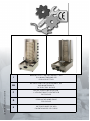
MODELS - PRODUITS - SERIE - GERÄTE - MODELOS
COD. 9841 COD. 9829 COD. 9830 COD. 9831 COD. 9832
COD. 9882 COD. 9849 COD. 9848
L'usine n'est pas responsible en cas de dommages dûs à une mauvaise utilization de ses produits ou
si les directives d'installation et d'utilisation n'étaient pas respectées
correctement.Merçi de lire
très attentivement le manuel d'installation et d'utilsation.
The manufacturing company, has no responsibility if the device broke up because of bad usage or
because the operation & installation instructions to the letter. Please read very carefully the opra-
tion instructions!
Il produttore declina ogni responsabilità in caso di danni dovuti ad una cattiva utilizzazione del prodotto
o se le direttive d' installazione e d' utilizzazione non vengono rispettate correttamente. Grazie di leggere
molto attentamente il manuale di installazione e di utilizzazione
El productor declina toda responsabilidad en caso de daños debido a una anormal utilización del pro-
ducto o si las directivas de la instalación y de la utilización no vengan respetadas correctamente
Muchas gracias por leer atentamente el manual de instalación y de utilización.
Die Erzeugung-Gesellschaft, hat keine Verantwortung, wenn das Gerät aufwärts wegen schlechter
Verwendung bräche, oder wegen des nicht Folgen der Bedienung & Installation-Anweisungen zum
Brief.
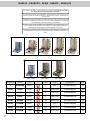
GY-INO10E 9841
GY40E 9829
GY60E 9830
GY80E 9831
GY100E 9832
GY20EIR 9882
GY70EIR 9849
GY90EIR 9848
3 230/1 400x450x590h 12
4.5 400/3+N 500x640x650h 24
6 400/3+N 500x640x810h 27
9 400/3+N 500x640x970h 30
12 400/3+N 500x640x1150h 32
3 230/1 400x500x600h 45
4,5 400/3+N 500x640x810h 32
6 400/3+N 500x640x970h 36
5
20÷25
30÷40
40÷50
50÷60
10÷15
35÷45
45÷55
M. Cap. kg Mod. Cod. Kw Volt Dimensions Kg

3
SERIE - MODELS - PRODUITS - GERÄTE - MODELOS
Le producteur informe que les appareils sont: conformes aux Directives:
93/68 CEE 89/336 CEE 73/23 CEE conformes aux Normes : EN 60 335-2-37 CEI-61-63 EN
55014 EN 60 555-2-3
The manufacturer deckares that the appliances are in compliance with the following Directions:
93/68 CEE 89/336 CEE 73/23 CEE.
The following Standards: EN 60 335-2-37 CEI-61-63 EN 55014 EN 60 555-2-3
Il produttore dichiara che le apparecchiature relative al presente manuale sono: conformi alle seguenti
Direttive:93/68 CEE 83/336 CEE 73/23 CEE conformi alle seguenti Norme:
EN 60 335-2-37 CEI-61-63 EN 55014 EN 60 555-2-3
El productor declara que los aparatos relativos al presente manual son conformes a las siguientes
Directivas: 93/68 CEE 83/336 CEE 73/23 CEE EN 60 335-2-37 CEE 61-63 EN 55014 EN 60
555-2-3
Der Hersteller erklärt, daß die in diesel Gebrauchsanweisung beschriebenen Geräte den folgeden
Richtlinien: 93/68 CEE 89/336 CEE 73/23 CEE
und Vorschriften: EN 60-335-2-37 CEI-61-63 E
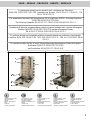
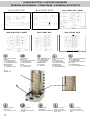
1 Interruttore Marcia / Arresto
2 Regolatore di distanza
3 Spiedo
4 Manopola regolazione resistenze
5 Cassetto raccogli grassi
6 Vetroceramica
7 Maniglia reg. distanza Resistenze
1 ON - OFF Motor's button
2 Top Distance Regulator
3 Top Spit's reception
4 Resistance's Operation Switch
5 Drawer
6 Ceramic Glass
7 Handle regulation heating El.
1 Bouton marche/arret moteur
2 Régulation distance
3 Broche
4 Bouton réglace résistance
5 Tiroir
6 Vitroceran
7 Poignèe reglage distance
1 Ein-Aus Schalter von Motor
2 Distanzregelung
3 Spieße
4 Knopf für Heizungsregelung
5 Fettschublade
6 Glass-Ceran
7 Knopf regelung Abstand Heitzk.
1 Interruptor marcha/arresto
2 Regulador de distancia
3 Asador
4 Manopla regulador resistencias
5 Cajón recoge grasas
6 Vidrio cerámica
7 Manija reg. distancia resistencias
1
1
5
5
7
7
6
2
2
3
3
4
4

4
FIG. 2
1 Cassetto raccolta grassi
2 Spiedo In Acciaio Inox
3 Meccanismo di rotazione ed
appoggio Spiedo
1 Drawer to collect oil
2 Inox Split
3 Bottom support Mechanism for
Inox Split
1 Tiroir de récuperation
2 Broche inox
3 Fond et méchanisme broche
1 Auffangsschublade
2 Edelstahl Spieß
3 Drehantrieb und Spießhalterung
1 Recipiente recoge graso
2 Asador en acero inoxidable
3 Mecanismo de rotación y apoyo
Asador
- ER1÷6 - REGULATEUR D'
ENERGIE
- R1÷R6 - RESISTANCES
- M - MOTOREDUCTEUR
- IM - INTERREPTEUR POUR
MOTOREDUCTEUR
- KN - BOITIERE
- PL - PRISE DE COURANT
- ER1÷6 - ENERGY
REGULATOR
- R1÷R6 - HEATING ELEMENTS
- M - MOTOREDUCTOR
- IM - MOTOREDUCTOR
SWITCH
- KN - SWITCH BOARD
- PL - ELECTRIC PLUG
- ER1÷6 - REGOLATORE D'
ENERGIA
- R1÷R6 - RESISTENZE
- M - MOTORIDUTTORE
- IM - INTERRUTTORE PER
MOTORIDUTTORE
- Kn - MORSETTIERA
- PL - PRESA DI CORRENTE
- ER1:6 REGULADOR DE ENERGÍA
- R1:R6 RESISTENCIAS
- M - MOTOREDUCTOR
- IM - INTERRUPTOR PARA MOTO-
REDUCTOR
- KN - ABRAZADERAS
- PL - TOMA DE CORRIENTE EN 60
- ER1÷6 - ENERGIEREGLER
- R1÷R6 - RESISTANCIAS
- M - GETRIEBEMOTOR
- IM - SCHALTER FÜR
GETRIEBEMOTOR
- Kn - KLEMME
- PL - STECKDOSE
Mod. GYROS 40 E / 70EIR
Mod. GYROS 60 E / 90EIR Mod. GYROS 80 E Mod. GYROS 100 E
Mod. GYROS 10 E Mod. GYROS 20 EIR
2
1
3
SCHEMI ELETTRICI - ELECTRIC DIAGRAMS
SCHEMAS ELECTRIQUES - SCHALTPLAN - ESQUEMAS ELECTRICOS

1. INSTALLATION
1.1 The installation, & the connection of the device must be done only by authorized technicians always according to the laws & ordinances, which
are valid.
1.2 Remove carefully the plastic coverage from all parts of metallic surface of the device ahead & rear so as to be clear without plastic residues.
For better cleaning use gasoline with oil or petrol.
1.3 The device must be located at least 2cm away from an incombustible wall
2. OPERATION INSTRUCTIONS
ATTENTION !!!
· This device is designed only for professional use & must be used exclusively by experienced & well-trained personnel.
· The device must be constantly supervised during its usage.
2.1 BEFORE TURNING THE DEVICE ON
We would like to advice you to clean thoroughly the GYROS before to begin to use the machine. See the paragraph " Instructions for the cleaning of this device".
2.2 TURNING ON THE RESISTENCE (figure 1)
In order to turn the heating elements on you have to turn the heating elements operation switch No 7 right (clockwise)
The first knob controls the two first heating elements , and the second knob controls the two last heating elements
2.3 PUTTING THE INOX SPIT (Figure - 1)
The device has to be switched off during the time that you place the spit with the meat on the machine.
You place the spit with the meat inside the bottom support base and at the same time you pull up the top round disk No-5, you place the spit in it´s place and
then you pull down the top round disk.
Before to operate your machine do a double check that the spit is well inside its position and none of the top or bottom spit´s supports move.
2.4 MOTOR´S FUNCTION
In order to begin motor´s function you have to push the button of the motor No 3 ( fig 1) at the position ON.
In order to cut the meat you can use electric knife on the plug No 1-fig 1 that is at the front of the machine. Attention the front plug can support up
to 250W maximum load.
2.5 DISTANCE REGULATION FROM THE RESISTENCE
In order to regulate the distance of the spit from the resistances, you have to pull out the movement mechanism No2 -fig1, the main body will move back or in
front at the distance you wish. You can as well regulate the distance of the spit by unscrewing the top regulator No4 and moving the top disk back or in front
to the desired position.
2.6 INSTRUCTIONS FOR THE CLEANUP OF THE DEVICE (Figure -2)
In no case should you clean the device with a flow of water or with a potent acid.
The use of acid might inflict rust to the metallic surfaces.
The cleanup must be done only when the device is cold & out of function.
It is necessary to clean the device after each operation.
You can clean the device with a sponge using only special products for stainless surfaces.
You can first put off and clean all the movable parts of your machine (See fig - 2).
WARNING !!!
Do not direct jets of water, against the appliance to prevent any water entering in the components. No water with or without pressure should be used underneath
the machine where is the motor and all the electric connections.
2.7 MAINTENANCE
The correct operation of your appliance is guaranteed only if these instructions are followed carefully.
Any repairs or maintenance operations must be performed only by qualified technicians.
We recommend to have the appliance controlled at least once a year, for this purpose it is advisable to apply for a service contract.
5
-
 1
1
-
 2
2
-
 3
3
-
 4
4
-
 5
5
-
 6
6


Diamond GY60E Instructions For Assembly, Use And Maintenance
- Taper
- Instructions For Assembly, Use And Maintenance
dans d''autres langues
- English: Diamond GY60E
Autres documents
-
Sammic AG-30 Manuel utilisateur
-
Silvercrest SHFR 1450 A1 Mode d'emploi
-
BOMANN DVG 3686 Manuel utilisateur
-
HQ RC UNI/AIRC03 spécification
-
 RC Logger RC EYE One Manuel utilisateur
-
Neff T47TD7BN2 Le manuel du propriétaire
-
Siemens EX975LVV1E HOME CONNECT Le manuel du propriétaire
-
Gaggenau VI 422 611 Mode d'emploi
-
Gaggenau VI230 Le manuel du propriétaire
