RIDGID GP80150RTB Manuel utilisateur
- Catégorie
- Compresseurs d'air
- Taper
- Manuel utilisateur

OPERATOR’S MANUAL
MANUEL D’UTILISATION
MANUAL DEL OPERADOR
8 GALLON PORTABLE AIR COMPRESSOR
COMPRESSEUR D’AIR PORTABLE
DE 30,2 LITRES (8 GALLONS)
COMPRESOR DE AIRE PORTÁTIL
DE 30,2 LITROS (8 GALONES)
GP80150RTB
SAVE THIS MANUAL FOR
FUTURE REFERENCE
CONSERVER CE MANUEL
POUR FUTURE RÉFÉRENCE
GUARDE ESTE MANUAL
PARA FUTURAS CONSULTAS
WARNING:
To reduce the risk of injury, the
user must read and understand
the operator’s manual before
using this product.
AVERTISSEMENT :
Pour réduire les risques de
blessures, l’utilisateur doit lire
et veiller à bien comprendre
le manuel d’utilisation avant
d’utiliser ce produit.
ADVERTENCIA:
Para reducir el riesgo de
lesiones, el usuario debe leer
y comprender el manual del
operador antes de usar este
producto.
INCLUDES: Air Compressor, Feet, Wheels,
Mounting Hardware, Engine Oil, Pump Oil,
Operator’s Manual
TABLE OF CONTENTS
****************
General Safety Rules .......................3-4
Specific Safety Rules .........................5
Symbols ..............................................6
Glossary of Terms ...............................7
Special Terms .....................................7
Features ..............................................8
Assembly .........................................8-9
Operation .....................................10-16
Maintenance ................................17-20
Troubleshooting ...........................20-21
Warranty ......................................22-23
Illustrations ..................................24-31
Parts Ordering / Service ..... Back Page
INCLUT : Compresseur d’air, pieds, roues,
quincaillerie de montage, huile moteur, huile
pompe, manuel d’utilisation
TABLE DES MATIÈRES
****************
Règles de sécurité générales ............. 3-4
Règles de sécurité particulières .............5
Symboles ...............................................6
Glossaire ................................................7
Termes spécialisés .................................7
Caractéristiques .....................................8
Assemblage........................................ 8-9
Utilisation ....................................... 10-16
Entretien ......................................... 17-20
Dépannage ..................................... 20-21
Garantie .......................................... 22-23
Illustrations ..................................... 24-31
Commande de pièces /
réparation ............................. Page arrière
INCLUYE: Compresor de aire, patas, ruedas,
piezas de montaje, aceite para motor, aceite
de bomba, manual del operador
ÍNDICE DE CONTENIDO
****************
Reglas de seguridad generales .......... 3-4
Reglas de seguridad específicas ...........5
Símbolos ................................................6
Glosario de términos .............................. 7
Términos especiales ..............................7
Características .......................................8
Armado ............................................... 8-9
Funcionamiento.............................. 10-16
Mantenimiento ............................... 17-20
Solución de problemas .................. 20-21
Garantía .......................................... 22-23
Ilustraciones ................................... 24-31
Pedidos de piezas /
servicio .............................. Pág. posterior
To register your RIDGID product, please
visit: http://register.RIDGID.com
Pour enregistrer votre produit de
RIDGID, s’il vous plaît la visite :
http://register.RIDGID.com
Para registrar su producto
de RIDGID, por favor visita:
http://register.RIDGID.com

2
DANGER:
This compressor/pump is not equipped and should not be used to supply breathing quality air. Additional equip-
ment would be necessary to properly filter and purify the air to meet minimal specifications for Grade D breathing
as described in Compressed Gas Association Commodity Specification G 7.1 - 1966, OSHA 29 CFR 1910.134.
Compressed Gas Association, 4221 Walney Road, Fifth Floor, Chantilly, VA 20151-2923, (703) 788-2700,
www.cganet.com. Any such additional equipment has not been examined and no implication of proper use for
breathing air is intended or implied.
If this compressor is altered in any way, existing warranties shall be voided. RIDGID® and One World Technologies,
Inc., disclaim any liabilities whatsoever for any loss, personal injury, or damage.
DISCLAIMER OF WARRANTIES
In the event the compressor is used for the purpose of breathing air application and proper in-line safety and alarm
equipment is not simultaneously used, existing warranties shall be voided, and RIDGID® disclaims any liabilities
whatsoever for any loss, personal injury, or damage.
DANGER :
Ce compresseur / pompe n’est pas équipé et ne doit pas être utiliser pour fournir de l’air de qualité respirable. Un
équipement supplémentaire est nécessaire pour filtrer et purifier l’air conformément aux spécifications minimum
d’air respirable de qualité D G 7.1 - 1966, OSHA 29 CFR 1910. 134 de la Compressed Gas Association, 4221
Walney Road, Fifth Floor, Chantilly, VA 20151-2923, (703) 788-2700, www.cganet.com. Un tel équipement n’a pas
été examiné et nulle implacation d’utilisation propre pour l’air respirable n’est prévue ou implicite.
Si ce compresseur est modifier de quelle que manière que ce soit, les garanties en vigueur seront déclarées
nulles et non avenues. RIDGID®. et One World Technologies, Inc., déclineront toute responsabilité pour les pertes,
blessures et dommages résultant de son utilisation.
EXONÉRATION DE GARANTIES
Si ce compresseur est utilisé pour des applications d’air respirable sans un système de sécurité et d’alarme
approprié, les garanties en vigueur seront déclarées nulles et non avenues et RIDGID® déclinera toute responsabilité
pour les pertes, blessures et dommages résultant de son utilisation.
PELIGRO:
Este compresor (o bomba) no está equipado y debe evitarse utilizarlo para suministrar aire para respirar. Es necesario
equipo adicional para filtrar y purificar debidamente el aire a fin de que cumpla las especificaciones mínimas de
Grado D para respiración, según se explica en la Especificación de Productos G 7.1 - 1966 de la Asociación de
Proveedores de Equipo de Gas Comprimido (Compressed Gas Association), OSHA 29 CFR 1910.134. Compressed
Gas Association, 4221 Walney Road, Fifth Floor, Chantilly, VA 20151-2923, (703) 788-2700, www.cganet.com.
Tal equipo adicional no ha sido examinado y no debe suponerse o deducirse ninguna conclusión con respecto
al correcto uso del aire de respiración.
Si se altera de cualquier forma este compresor, quedan anuladas todas las garantías presentes. RIDGID®. y
One World Technologies, Inc., se eximen de toda responsabilidad de cualquier tipo por cualquier pérdida, lesión
corporal o daño material.
EXTENCIÓN DE RESPONSABILIDAD DE LAS GARANTÍAS
En caso de utilizarse los compresores para suministrar aire de respiración, y no utilizarse simultáneamente equipo
en línea de seguridad y alarma apropiado, se anulan todas las garantías presentes, y RIDGID® se exime de toda
responsabilidad de cualquier tipo por cualquier pérdida, lesión física o daño material que resulte.

3 – English
GENERAL SAFETY RULES
WARNING:
Read and understand all instructions. Failure
to follow all instructions listed below may result
in electric shock, fire and/or carbon monoxide
poisoning which will cause death or serious per-
sonal injury.
SAVE THESE INSTRUCTIONS
WORK AREA
Keep your work area clean and well lit. Cluttered
benches and dark areas invite accidents. Floor must not
be slippery from wax or dust.
Do not operate air compressors in explosive atmo-
spheres, such as in the presence of flammable liquids,
gases, or dust. Air compressors create sparks which may
ignite the dust or fumes.
Keep bystanders, children, and visitors away while
operating an air compressor. Distractions can cause you
to lose control.
Operate air compressor in an open area at least 18 in.
away from any wall or object that could restrict the
flow of fresh air to ventilation openings.
PERSONAL SAFETY
Always wear eye protection with side shields marked
to comply with ANSI Z87.1 as well as hearing protec-
tion when operating this equipment.
The employer and/or user must ensure that proper
eye protection is worn. We recommend a Wide Vision
Safety Mask for use over eyeglasses or standard safety
glasses that provide protection against flying particles
both from the front and side. Always use eye protection
which is marked to comply with ANSI Z87.1.
Additional safety protection will be required in some
environments. For example, the working area may
include exposure to a noise level which can lead to hear-
ing damage. The employer and user must ensure that any
necessary hearing protection is provided and used by the
operator and others in the work area. Some environments
will require the use of head protection equipment. When
required, the employer and user must ensure that head
protection marked to comply with ANSI Z89.1 is used.
Stay alert, watch what you are doing, and use com-
mon sense when operating the air compressor. Do
not use product while tired or under the influence of
drugs, alcohol, or medication. A moment of inattention
while operating an air compressor may result in serious
personal injury.
Dress properly. Do not wear loose clothing or jewelry.
Contain long hair. Keep your hair, clothing, and gloves
away from moving parts. Loose clothes, jewelry, or long
hair can be caught in moving parts.
Do not overreach. Keep proper footing and balance
at all times. Proper footing and balance enables better
control of the product in unexpected situations.
Use safety equipment. Always wear eye protection.
Dust mask, nonskid safety shoes, hard hat, or hearing
protection must be used for appropriate conditions.
Do not use on a ladder or unstable support. Stable
footing on a solid surface enables better control of the
air compressor in unexpected situations.
AIR COMPRESSOR USE AND CARE
For outdoor use only.
Do not exceed the pressure rating of any component
in the system.
Protect material lines and air lines from damage or
puncture. Keep hose away from sharp objects, chemical
spills, oil, solvents, and wet floors.
Check hoses for weak or worn condition before each
use, making certain all connections are secure. Do not
use if defect is found. Purchase a new hose or notify a
qualified service center for examination or repair.
Release all pressures within the system slowly. Dust
and debris may be harmful.
Store idle air compressors out of the reach of children
and other untrained persons. Air compressors are dan-
gerous in the hands of untrained users.
Maintain air compressors with care. Follow mainte-
nance instructions. Properly maintained products are
easier to control.
Check for misalignment or binding of moving parts,
breakage of parts, and any other condition that may
affect the product’s operation. If damaged, have the
air compressor serviced before using. Many accidents
are caused by poorly maintained products.
Keep the exterior of the air compressor dry, clean, and
free from oil and grease. Always use a clean cloth when
cleaning. Never use brake fluids, gasoline, petroleum-
based products, or any strong solvents to clean the unit.
Following this rule will reduce the risk of deterioration of
the enclosure plastic.
Keep the engine free of grass, leaves, or grease to
reduce the chance of a fire hazard.
Keep guards in place and in working order. Never oper-
ate the tool with any guard or cover removed. Make sure
all guards are operating properly before each use.
Do not operate the engine in a confined space where
dangerous carbon monoxide fumes can collect. Carbon
monoxide, a colorless, odorless, and extremely danger-
ous gas, can cause unconsciousness or death.
Keep the exhaust pipe free of foreign objects.
Do not operate around dry brush, twigs, cloth rags, or
other flammable materials.

4 – English
GENERAL SAFETY RULES
Never pick up or carry a machine while the engine is
running.
Never start the machine if ice has formed in any part
of the equipment.
Always operate the machine on a level surface. If the
engine is on an incline, it could seize due to improper
lubrication (even at the maximum oil level).
Never attempt to make any adjustments while the
engine (motor) is running (except where specifically
recommended by the manufacturer).
Protective covers must always cover rotating parts
when the engine is running.
Keep cooling air intake (recoil starter area) and muffler
side of the engine at least 3 feet away from buildings,
obstructions, and other combustible objects.
Keep the engine away from flammables and other
hazardous materials.
Keep away from hot parts. The muffler and other engine
parts become very hot; use caution.
Do not touch the spark plug and ignition cable when
starting and operating the engine.
Check fuel hoses and joints for looseness and fuel
leakage before each use.
Check bolts and nuts for looseness before each use.
A loose bolt or nut may cause serious engine problems.
Always refuel outdoors. Never refuel indoors or in a
poorly ventilated area.
Never store the machine with fuel in the fuel tank
inside a building where ignition sources are present,
such as hot water and space heaters, clothes dryers,
and the like.
If the fuel tank has to be drained, do this outdoors into
a container approved for gasoline and away from all
ignition sources.
To reduce the risk of fire and burn injury, handle fuel
with care. It is highly flammable.
Do not smoke while handling fuel.
Add fuel before starting the engine. Never remove the
cap of the fuel tank or add fuel while the engine is running
or when the engine is hot.
Loosen fuel cap slowly to release pressure and to keep
fuel from escaping around the cap.
Replace all fuel tank and container caps securely.
Wipe spilled fuel from the unit. Move 30 feet away from
refueling site before starting engine.
If fuel is spilled, do not attempt to start the engine but
move the machine away from the area of spillage and
avoid creating any source of ignition until fuel vapors
have dissipated.
Never attempt to burn off spilled fuel under any
circumstances.
Before storing, allow the engine to cool.
Store fuel in a cool, well-ventilated area, safely away
from spark and/or flame-producing equipment.
Store fuel in containers specifically designed for this
purpose.
Empty fuel tank and restrain the unit from moving
before transporting in a vehicle.
Make sure minimum clearance of 3 feet is maintained
from combustible materials.
SERVICE
When servicing a product, use only recommended or
equivalent replacement parts. Follow instructions in
the Maintenance section
of this manual. Use of unau-
thorized parts or failure to follow Maintenance instructions
may create a risk of injury.
Service must be performed only by qualified repair
personnel. Service or maintenance performed by
unqualified personnel may result in a risk of injury.
Disconnect the spark plug wire, open drain valve to
decompress tanks and allow water to drain, and allow
air compressor to become cool to the touch before
servicing. Turn pressure regulator knob fully counter-
clockwise after shutting off air compressor.

5 – English
SPECIFIC SAFETY RULES
Know your air compressor. Read operator’s manual
carefully. Learn its applications and limitations, as well
as the specific potential hazards related to this product.
Following this rule will reduce the risk of electric shock,
fire, or serious injury.
Drain tanks of moisture after each day’s use. If unit will
not be used for a while, it is best to leave drain valve open
until such time as it is to be used. This will allow moisture
to completely drain out and help prevent corrosion on the
inside of tanks.
Risk of Fire or Explosion. Do not spray flammable liquid
in a confined area. Spray area must be well ventilated. Do
not smoke while spraying or spray where spark or flame
is present. Keep compressors as far from the spraying
area as possible, at least 15 feet from the spraying area
and all explosive vapors.
Risk of Bursting. Do not adjust regulator to result in
output pressure greater than marked maximum pressure
of attachment. Do not use at pressure greater than 150 psi.
Inspect tanks yearly for rust, pin holes, or other
imperfections that could cause it to become unsafe.
Never weld or drill holes in the air tanks.
Make sure the hose is free of obstructions or snags.
Entangled or snarled hoses can cause loss of balance or
footing and may become damaged.
Use the air compressor only for its intended use. Do
not alter or modify the unit from the original design
or function.
Do not sit or stand on the air compressor frame or
attempt to use the frame as a work surface.
Always be aware that misuse and improper handling of
this product can cause injury to yourself and others.
Never leave a tool unattended with the air hose
attached.
Never point any air tool toward yourself or others.
Do not operate this air compressor if it does not
contain a legible warning label.
Do not continue to use a tool or hose that leaks air or
does not function properly.
Always disconnect the air supply and remove spark
plug wire before making adjustments, servicing a
product, or when a product is not in use.
Do not attempt to pull or carry the air compressor by
the hose.
Your tool may require more air consumption than this
air compressor is capable of providing.
Always follow all safety rules recommended by the
manufacturer of your air tool, in addition to all safety
rules for the air compressor. Following this rule will
reduce the risk of serious personal injury.
Never direct a jet of compressed air toward people or
animals. Take care not to blow dust and dirt towards
yourself or others. Following this rule will reduce the risk
of serious injury.
Do not use this air compressor to spray chemicals.
Your lungs can be damaged by inhaling toxic fumes. A
respirator may be necessary in dusty environments or
when spraying paint. Do not carry while painting.
Inspect hoses periodically and, if damaged, have
repaired at your nearest Qualified Service Center.
Check damaged parts. Before further use of the air
compressor or air tool, a guard or other part that is
damaged should be carefully checked to determine
that it will operate properly and perform its intended
function. Check for alignment of moving parts, binding
of moving parts, breakage of parts, mounting, and
any other conditions that may affect its operation. A
guard or other part that is damaged should be properly
repaired or replaced by a qualified service center.
Following this rule will reduce the risk of shock, fire, or
serious injury.
Never store a tool with air connected. Storing the tool
with air connected can result in unexpected firing and
possible serious personal injury.
Protect your lungs. Wear a face or dust mask if the
operation is dusty. Following this rule will reduce the risk
of serious personal injury.
Save these instructions. Refer to them frequently and use
them to instruct others who may use this product. If you
loan someone this product, loan them these instructions
also.

6 – English
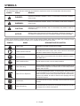
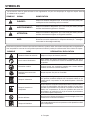
SYMBOLS
Some of the following symbols may be used on this product. Please study them and learn their meaning. Proper
interpretation of these symbols will allow you to operate the product better and safer.
Safety Alert Indicates a potential personal injury hazard.
Read Operator’s Manual
To reduce the risk of injury, user must read and understand
operator’s manual before using this product.
Eye Protection
Always wear eye protection with side shields marked to comply
with ANSI Z87.1.
Wet Conditions Alert Do not expose to rain or use in damp locations.
Risk of Bursting
Do not adjust regulator to result in output pressure greater than
marked maximum pressure of attachment. Do not use at pressure
greater than 150 PSI.
Risk of Fire or Explosion
Do not spray flammable liquid in a confined area. Spray area must
be well ventilated. Do not smoke while spraying or spray where
spark or flame is present. Keep compressors as far from the spray-
ing area as possible, at least 15 feet from the spraying area and
all explosive vapors.
Hot Surface
To reduce the risk of injury or damage, avoid contact with any hot
surface.
Risk to Breathing
Air obtained directly from the air compressor should never be used
to supply air for human consumption.
SYMBOL NAME
DESIGNATION/EXPLANATION
The following signal words and meanings are intended to explain the levels of risk associated with this product.
SYMBOL SIGNAL MEANING
DANGER:
Indicates a hazardous situation, which, if not avoided, will result in death or
serious injury.
WARNING:
Indicates a hazardous situation, which, if not avoided, could result in death or
serious injury.
CAUTION:
Indicates a hazardous situation, that, if not avoided, may result in minor or
moderate injury.
NOTICE:
(Without Safety Alert Symbol) Indicates information considered important, but
not related to a potential injury (e.g. messages relating to property damage).

7 – English
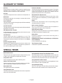
GLOSSARY OF TERMS
Pressure Unloader
Controls the speed of the compressor’s engine. The engine
runs at idle speed when the cut-off pressure in the tank is
reached and switches the engine to full speed once the
pressure drops below the cut-in pressure.
PSI (Pounds Per Square Inch)
Measurement of the pressure exerted by the force of the
air. The actual psi is measured by a pressure gauge on the
compressor.
Pump
Produces the compressed air with a reciprocating piston
contained within the cylinder.
Quick-connect Couplers
The 1/4 in. quick-connect couplers allow the operator to
easily attach air hoses to the compressor.
Outlet Pressure Gauge
Displays the current line pressure. Line pressure is adjusted
by rotating the pressure regulator knob.
Safety Valve
Prevents air pressure in the air tank from rising over a
predetermined limit.
SCFM (Standard Cubic Feet Per Minute) or CFM (Cubic
Feet Per Minute)
A unit of measure of air delivery.
Tank Pressure Gauge
Indicates the pressure in the air tank.
Air Filter
Porous element contained within a metal or plastic housing
attached to the compressor cylinder head which removes
impurities from the intake air of the compressor.
Air Tank
Cylindrical component which contains the compressed air.
Belt Guard
Protects the operator from coming in contact with the belt
and rotating pulleys.
Cut-In Pressure
The low pressure at which the engine speed will automatically
increase to full speed.
Cut-Off Pressure
The high pressure at which the engine speed will automatically
decrease to idle speed.
NPT (National Pipe Thread)
A seal thread tape must be used to provide a leak-free seal
on pipe threaded connections.
On/Off Switch
Control which turns the air compressor on or off. The
pressure switch will not automatically start and control the
compressor unless the manual on/off switch is in the ON ( l )
position.
Pressure Regulator Knob
Regulates the outgoing pressure from the air outlet to the
tool. It is possible to increase or decrease the pressure at
the outlet by adjusting this control knob.
SPECIAL TERMS
Belt Tensioner Bolt
This bolt moves the engine toward or away from the pump
to allow you to reposition or replace the drive belt.
Compressor Tank
The air compressor and 4 gallon stationary tank.
Quarter Turn Drain Valves
Quarter turn drain valves are located on tanks for easy drain-
ing of condensate to help prevent tank corrosion.
Removable Tank
The 4 gallon tank that is removable.
Unregulated Air Hose
This hose transmits the compressed air from the compressor
tank to the removable tank.
Unregulated Air Quarter Turn Ball Valve Lever
This valve opens to allow compressed air to flow from the
compressor tank to the removable tank and closes to stop
air flow from the compressor tank to the removable tank.
Unregulated Air Intake Coupler
This coupler is an air inlet only for the unregulated air hose
and is located on the removable tank.
Unregulated Air Fitting
This 1/4 in. NPT quick-connect fitting connects the unregu-
lated air hose and is located on the compressor tank.

8 – English
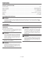
FEATURES
PRODUCT SPECIFICATIONS
Air Tank Capacity ........................................................................................................................................................... 8 gal.
Engine Oil Capacity ............................................................................................................................... Approximately 20 oz.
Pump Oil Capacity ................................................................................................................................ Approximately 27 oz.
Air Pressure .........................................................................................................................................................150 psi max.
Air Delivery ............................................................................................................................................. 10.2 SCFM @ 90 psi
Spark Plug ...............................................................................................................................Torch/LG F6RTC or equivalent
Engine...................................................................................................................................................................212 cc OHV
Gauges .............................................................................................................................................................. 2 in. diameter
WARNING:
This product, its exhaust, and other substances that may become airborne from its use may contain chemicals,
including lead, known to the State of California to cause cancer, birth defects, or other reproductive harm. Wash
hands after handling.
CALIFORNIA PROPOSITION 65
ASSEMBLY
UNPACKING
This product requires assembly.
Carefully remove the tool and any accessories from the
box. All items listed in the Includes section must be
included at the time of purchase.
WARNING:
Items in this Assembly section are not assembled
to the product by the manufacturer and require
customer installation. Use of a product that may
have been improperly assembled could result in
serious personal injury.
If any parts are damaged or missing, please call
1-866-539-1710 for assistance.
WARNING:
If any parts are damaged or missing do not operate
this product until the parts are replaced. Use of
this product with damaged or missing parts could
result in serious personal injury.
WARNING:
Do not attempt to modify this product or create
accessories or attachments not recommended
for use with this product. Any such alteration
or modification is misuse and could result in a
hazardous condition leading to possible serious
personal injury.
WARNING:
To prevent accidental starting that could cause
serious personal injury, always disconnect the
engine spark plug wire from the spark plug when
assembling parts.

9 – English
ASSEMBLY
LOOSE PARTS LIST
See Figure 1, page 24.
The following items are included with the air compressor:
Key
No. Description Qty.
1 Axle Bolt ..............................................................2
2 Lock Washer (18 mm) .......................................... 2
3 Flat Washer (18 mm) ............................................ 2
4 Spacer .................................................................2
5 Wheel ...................................................................2
6 Leg with Rubber Foot ..........................................2
7 Nut (5 mm) ...........................................................4
8 Flat Washer (5 mm) .............................................. 4
9 Lock Washer (5 mm) ............................................ 4
10 Screw ...................................................................4
Pump Oil (not shown) ..........................................1
Engine Oil (not shown) .........................................1
Operator’s Manual (not shown) ...........................1
TOOLS NEEDED
The following tools (not included) are needed for assembling
or maintaining the air compressor.
Hex Keys
Adjustable Wrench
NOTE: Do not put fuel or oil in the air compressor before
installing the legs and wheels.
INSTALLING LEGS
See Figure 2, page 25.
Locate the following items:
2 legs with rubber feet
4 lock washers (5 mm)
4 flat washers (5 mm)
4 nuts (5 mm)
4 screws
Raise the front end of the air compressor, where the pump
is located, high enough to gain access to the frame bot-
tom; securely position props underneath to support.
Position a leg over the holes on each side of the frame.
Insert each screw through a lock washer and a flat washer,
then insert the screws through the two holes in the leg
and the frame.
Install a nut over each screw on the inside of the frame
and tighten securely.
Repeat with remaining leg.
INSTALLING THE WHEELS
See Figure 3, page 25.
Locate the following items:
2 axle bolts
2 spacers
2 lock washers (18 mm)
2 flat washers (18 mm)
2 wheels
Raise the back end of the air compressor, where the
engine is located, high enough to gain access to the frame
bottom; securely position props underneath to support.
Insert a wheel spacer into the center of the wheel.
Insert axle bolt through lock washer and flat washer,
through the spacer and wheel, and then into threaded
opening on air compressor frame. Tighten axle bolt
securely.
Repeat the process on the other side to install second
wheel.
REMOVING THE PUMP OIL LABEL
See Figure 4, page 25.
The air compressor has a label installed between the pump
oil cap and the oil fill hole. Before using the unit the first time,
remove the pump oil cap and label, then reinstall the cap.
Make sure to add oil before first use. See Adding/Checking
Pump Oil before first time operation.

10 – English
OPERATION
DANGER:
Carbon Monoxide. Using a gas-powered air
compressor indoors CAN KILL YOU IN MINUTES.
Engine exhaust contains high levels of carbon
monoxide (CO), a poisonous gas you cannot see
or smell. If you can smell the engine exhaust, you
are breathing CO. But even if you cannot smell the
exhaust, you could be breathing CO.
Never use a gas-powered air compressor
inside homes, garages, crawlspaces, or other
partly enclosed areas. Deadly levels of carbon
monoxide can build up in these areas. Using a
fan or opening windows and doors does NOT
supply enough fresh air.
ONLY use gas-powered air compressors
outdoors and far away from open windows,
doors, and vents. These openings can pull in
engine exhaust.
Even when you use a gas-powered air compressor
correctly, CO may leak into the home. ALWAYS use
a battery-powered or battery-backup CO alarm in
the home.
If you start to feel sick, dizzy, or weak after the air
compressor has been running, move to fresh air
RIGHT AWAY. See a doctor. You could have carbon
monoxide poisoning.
DANGER:
Do not disassemble pressure unloader, tank drain
valves or safety relief valve with air in tank — bleed
tanks.
WARNING:
Do not allow familiarity with products to make you
careless. Remember that a careless fraction of a
second is sufficient to inflict severe injury.
WARNING:
Always wear eye protection with side shields
marked to comply with ANSI Z87.1. Failure to do
so could result in objects being thrown into your
eyes resulting in possible serious injury.
WARNING:
Never direct a jet of compressed air toward people
or animals. Take care not to blow dust and dirt
towards yourself or others. Following this rule will
reduce the risk of serious injury.
WARNING:
Do not attach any tools to the open end of the hose
until start-up has been completed.
NOTICE:
Do not use in an environment that is dusty or
otherwise contaminated. Using the air compressor
in this type of environment may cause damage to
the unit.
NOTICE:
This product is equipped with a spark arrestor that
has been evaluated by the USDA Forest Service;
however, product users must comply with Federal,
State, and local fire prevention regulations. Check
with appropriate authorities. Contact customer
service or a qualified service center to purchase a
replacement spark arrestor.
NOTICE:
Before each use, inspect the entire product for
damaged, missing, or loose parts such as screws,
nuts, bolts, caps, etc. Tighten securely all fasteners
and caps and do not operate this product until all
missing or damaged parts are replaced. Please
contact customer service or a qualified service
center for assistance.
APPLICATIONS
Air compressors are utilized in a variety of air system
applications. Match hoses, connectors, air tools, and
accessories to the capabilities of the air compressor.
You may use this product for the purposes listed below:
Operating some air-powered tools
Operating air accessories such as air nozzles and tire
inflators
Operating some air-powered paint spraying products
RAISING AND LOWERING THE HANDLE
See Figure 5, page 25.
To raise the handle (for moving the air compressor): pull
the handle up until the handle release knob snaps into
locking position and insert the handle lock pin to secure
the handle in place.

11 – English
To lower the handle (for storing or transporting the air
compressor): remove the handle lock pin, then pull the
handle release knob out and lower the handle to the down
position.
Never use the handle to lift the air compressor. The handle
should only be used for moving the unit by rolling it on its
wheels.
ADDING/CHECKING ENGINE OIL
See Figures 6 - 7, page 25.
NOTE: This machine has been shipped with approximately
2 oz. of oil in the engine from testing. You must add oil to
the engine before starting it the first time.
NOTICE:
Any attempt to start the engine without adding oil
will result in engine failure.
To add engine oil:
Place air compressor on a flat, level surface. Do not tilt.
Unscrew the engine oil cap/dipstick by turning counter-
clockwise.
Add 4-stroke engine oil (SAE 10W-30) until the fluid level
rises to the upper portion of the hatched area on the
dipstick. Do not overfill.
NOTE: Avoid using too much oil. Ensure that the level of
oil does not rise above the upper hatched area. For easier
access when adding engine oil, use a long-neck funnel.
Replace the engine oil cap/dipstick and securely tighten.
To check engine oil level:
Place air compressor on a flat, level surface. Do not tilt.
Remove engine oil cap/dipstick.
Wipe engine oil cap/dipstick clean and re-seat in hole.
Do not rethread.
Remove engine oil cap/dipstick again and check oil level. Oil
level should be near the upper hatched area on the dipstick.
If level is low, add engine oil until the fluid level rises to
the upper portion of the hatched area on the dipstick.
Replace and secure the engine oil cap/dipstick.
NOTICE:
Do not overfill. Overfilling the crankcase may cause
excessive smoke and engine damage.
ADDING/CHECKING PUMP OIL
See Figure 8, page 25.
NOTE: There is no pump oil in the unit when shipped from
the factory. You must add oil to the pump before using
the air compressor.
OPERATION
Unscrew the pump oil cap by turning counterclockwise.
Add SAE 5W-40 synthetic pump oil into the oil reservoir
until the fluid level rises to the top of the red dot in the
center of the sight glass. Do not overfill.
NOTE: Avoid using too much oil. Ensure that the level
of the oil does not exceed the top of the red dot in the
center of the sight glass. For easier access when adding
pump oil, use a long-neck funnel.
NOTICE:
Pump oil drains very slowly from the fill area into
the pump. Pause often while filling to allow the oil
to drain completely into the pump before checking
the level in the sight glass.
Replace the pump oil cap and securely tighten.
ETHANOL-BLENDED FUELS
NOTICE:
Do not use E15 or E85 fuel in this product. It is
a violation of federal law and will damage the
unit and void your warranty. Only use unleaded
gasoline containing up to 10% ethanol.
ADDING GASOLINE TO THE FUEL TANK
See Figure 9, page 25.
DANGER:
Risk of fire and serious burns: Never remove
fuel cap when unit is running. Shut off engine and
allow the unit to cool at least five minutes. Remove
cap slowly.
WARNING:
Gasoline and its vapors are highly flammable and
explosive. To prevent serious personal injury and
property damage, handle gasoline with care. Keep
away from ignition sources, handle outdoors only,
do not smoke while adding fuel, and wipe up spills
immediately.
When adding gas to the air compressor, make sure the unit
is sitting on a flat, level surface. If the engine is hot, let the
air compressor cool before adding gas. ALWAYS fill the fuel
tank outdoors with the machine turned off.
NOTE: Use unleaded gas only. DO NOT mix oil with gas.
Before removing the fuel cap, clean the area around it.
Remove the fuel cap.
Insert a clean funnel into the fuel tank then slowly
pour gasoline into the tank. Fill tank to approximately
1-1/2 in. below the top of the tank neck (this allows for
fuel expansion).

12 – English
OPERATION
Replace fuel cap and tighten securely.
Clean up any spills before starting the engine.
WARNING:
Always shut off engine before fueling. Never
remove fuel cap or add fuel to a machine with
a running or hot engine. Make sure the unit is
sitting on a flat, level surface and only add fuel
outdoors. If the engine is hot, let the unit cool
for at least five minutes before adding fuel. After
fueling, immediately replace fuel cap and tighten
securely. Move at least 30 ft. from refueling site
before starting engine. Do not smoke and stay
away from open flames and sparks! Failure to
follow these instructions could result in a fire and
cause serious personal injury.
CONNECTING/DISCONNECTING AIR HOSE
(NOT PROVIDED)
See Figure 10, page 25.
WARNING:
Never exceed the air tool’s pressure rating as
recommended by the manufacturer. When using
this air compressor as an inflation device, always
follow the maximum inflation guidelines stated by
the manufacturer of the item being inflated.
Make sure the air compressor is off.
Rotate pressure regulator knob fully in the counter-
clockwise direction so that the outlet pressure is at zero
(0) psi.
Attach an air hose with 1/4 in. NPT quick-connect air fitting
to a quick-connect coupler (1/4 in.) on air compressor.
Make sure to push the air fitting fully into the coupler until
the sleeve springs forward to lock in place.
To disconnect an air hose or an air tool:
Make sure the air compressor is off.
Confirm that the outlet pressure is at zero (0) psi.
When disconnecting a hose from quick-connect coupler
(1/4 in.), always firmly hold fitting end of hose.
Pull back on the release sleeve on the 1/4 in. quick-
connect coupler.
With a firm grip, pull out the quick-connect air fitting that
is attached to the quick-connect coupler.
BREAK-IN PERIOD
Before first use, run the air compressor at zero tank pressure
with the drain valves fully open for 30 minutes.
STARTING AND STOPPING THE AIR
COMPRESSOR
See Figures 11 - 15, page 26.
NOTICE:
On a level surface with the engine off, check the
pump and engine oil levels before each use of the
compressor.
Before starting the engine:
Connect all hoses.
Check all fluids (oil and gas).
To start the engine:
Turn the fuel valve to the OPEN position.
Move the choke lever to the START position.
NOTE: If the engine is warm, leave the choke lever in the
RUN position.
Place the pressure unloader in the vertical position.
Put the on/off switch in the ON (I) position.
KEEP AT LEAST
20 FT. AWAY
CO Detector
in Living Areas
Only use OUTSIDE and
FAR AWAY from windows,
doors, and vents.
LOCATE AIR COMPRESSOR AT LEAST 20 FT.* AWAY TO REDUCE
THE RISK OF CARBON MONOXIDE GETTING INSIDE THE HOME
* Minimum distance as recommended by U.S. Department of Health and Human
Services Centers for Disease Control and Prevention (www.cdc.gov/co). Your specific
home and/or wind conditions may require additional distance.
Exhaust (CO)
Direct exhaust AWAY
from all windows, doors,
and vents.

13 – English
OPERATION
Grasp the recoil starter and pull slowly until resistance is
felt. Give the recoil starter a short, brisk pull to start the
engine (no more than 4 pulls).
NOTE: Do not allow the recoil starter to snap back after
starting; return it gently to its original place.
NOTE: If the engine fails to start, wait several minutes
then repeat the above steps as needed.
Allow the engine to run for 30 seconds, then move the
choke lever to the RUN position and place the pressure
unloader in the horizontal position.
NOTE: Once the air compressor is started, pressure
inside the air tank will build until the compressor reaches
150 psi. After reaching maximum tank pressure the
engine will idle allowing the pressure inside the air tank to
decrease until it reaches a preset level. When the pressure
falls below the preset level, the engine will accelerate and
provide additional air pressure.
WARNING:
Never exceed the air tool’s pressure rating as
recommended by the manufacturer. When using
this air compressor as an inflation device, always
follow the maximum inflation guidelines stated by
the manufacturer of the item being inflated.
To stop the engine:
Put the on/off switch in the OFF (O) position.
WARNING:
The pump will become hot during use. Avoid
contact with the pump when stopping the engine.
WARNING:
Always ensure the on/off switch is in the OFF (O)
position and the outlet pressure gauge reads zero
before changing air tools or disconnecting the hose
from the air outlet. Failure to do so could result in
possible serious personal injury.
Turn the fuel valve to the CLOSED position.
USING THE AIR COMPRESSOR
This air compressor can be operated in 3 arrangements for
easy carry and ease of use.
NOTE: Before using the air compressor, always check the
safety valves for proper function as described in Checking
the Safety Valves later in this manual.
CAUTION:
Only use removable tank with air compressor Model
No. GP80150RTB to avoid damage to the tool or
risk of personal injury.
WARNING:
The compressor tank will become hot during use.
Failure to avoid contact with the hot surface may
result in serious personal injury.
NOTICE:
Keep the air compressor on a flat, level surface
during operation. Operation of the unit at an angle
may result in damage to the air compressor and
could void your warranty.
COMPRESSOR TANK AND REMOVABLE TANK
TOGETHER — FOR MAXIMUM TANK CAPACITY
See Figures 16 - 18, pages 26 - 27.
Keep compressor tank and removable tank together for
maximum tank capacity.
Make sure the air compressor is off.
Attach hose(s) to either or both of the quick-connect
couplers (1/4 in.) on removable tank.
NOTE: If two tools are installed on the removable tank,
they must use the same psi.
Attach a 1/4 in. NPT quick-connect air fitting to accessory
or tool(s) you intend to use.
Insert the other end of the quick-connect air fitting to the
quick coupler on the open end of hose.
Start the air compressor as described in Starting and
Stopping the Air Compressor.
Check that ball valve lever on unregulated air hose is in
the ON position, allowing air flow from compressor tank
to removable tank.
Pull out and rotate pressure regulator knob to desired
line pressure. Turning the knob clockwise increases air
pressure at the outlets; turning counterclockwise reduces
air pressure at the outlets.
Following all safety precautions in this manual and the
manufacturer’s instructions in the air tool manual, you
may now proceed to use your air-powered tool.

14 – English
OPERATION
CAUTION:
Air powered tools may require more air consumption
than this air compressor is capable of providing.
Check the tool manual to avoid damage to the tool
or risk of personal injury.
Control the amount of air flow with the pressure regulator
knob. Turning the knob fully counterclockwise will
completely stop the flow of air.
NOTE: Always use the minimum amount of pressure
necessary for your application. Using a higher pressure
than needed will drain air from the tank more rapidly and
cause the unit to cycle on more frequently.
When finished, always stop the engine and drain the
tanks. Never leave the unit running unattended.
REMOVABLE TANK ALONE — REGULATED
CARRY TANK FOR SMALL JOBS
See Figures 16 - 17 and 19, pages 26 - 27.
The removable tank can be separated from compressor
tank to be carried to remote location for small jobs. One tool
should be used in this instance.
Make sure the air compressor is off.
Rotate pressure regulator knob fully in the counterclock-
wise direction so that the outlet pressure is at zero (0) psi.
Turn ball valve lever on unregulated air hose to OFF posi-
tion.
NOTE: Be sure unregulated air hose is turned off before
connecting or disconnecting from unregulated air intake
coupler.
Disconnect unregulated air hose.
Carefully lift and remove removable tank from compressor
tank and move removable tank to job site.
WARNING:
The compressor tank will become hot during use.
Failure to avoid contact with the hot surface may
result in serious personal injury.
Attach hose to one of the two quick-connect couplers
located on front gauge panel of the removable tank as
previously instructed.
Attach 1/4 in. NPT quick-connect air fitting to accessory
or tool you intend to use.
Insert the other end of the quick-connect air fitting to the
quick-connect coupler on the open end of hose.
Pull out and rotate pressure regulator knob to desired
line pressure. Turning the knob clockwise increases air
pressure at the outlet; turning counterclockwise reduces
air pressure at the outlet.
Following all safety precautions in this manual and the
manufacturer’s instructions in the air tool manual, you
may now proceed to use your air-powered tool.
CAUTION:
Air powered tools may require more air consumption
than this air compressor is capable of providing.
Check the tool manual to avoid damage to the tool
or risk of personal injury.
Control the amount of air flow with the pressure regulator
knob. Turning the knob fully counterclockwise will
completely stop the flow of air.
NOTE: Always use the minimum amount of pressure
necessary for your application. Using a higher pressure
than needed will drain air from the tank more rapidly and
cause the unit to cycle on more frequently.
When finished, drain the removable tank.
Allow air compressor to cool then replace tank.
COMPRESSOR TANK AND REMOVABLE TANK
SEPARATED AND CONNECTED WITH A HOSE
See Figures 16 - 17 and 20, pages 26 - 27.
The compressor tank and removable tank can be separated
and connected with a hose (up to 50 ft.) for maximum flex-
ibility at job site, remote regulation, to prevent pressure drop
and to keep noise outside.
Make sure the air compressor is off.
Rotate pressure regulator knob fully in the counterclock-
wise direction so that the outlet pressure is at zero (0) psi.
Turn ball valve lever on unregulated air hose to OFF posi-
tion.
NOTE: Be sure unregulated air hose is turned off before
connecting or disconnecting from unregulated air intake
coupler.
Disconnect unregulated air hose.
Carefully lift and remove removable tank from compressor
tank.
Attach unregulated air hose on compressor tank to air
hose (up to 50 ft.).
Attach a 1/4 in. NPT quick-connect air fitting to air hose
and connect to 1/4 in. quick-connect intake coupler on
removable tank.
WARNING:
Only connect unregulated air hose between
compressor tank and unregulated air intake
coupler.
Move removable tank to job area.
Attach hose to one of the two quick-connect couplers
located on front gauge panel of the removable tank as
previously instructed.
NOTE: If two tools are installed on the removable tank,
they must use the same psi.
Attach 1/4 in. NPT quick-connect air fitting to accessory
or tool you intend to use.

15 – English
Insert the other end of the quick-connect air fitting to the
quick-connect coupler on the open end of hose.
Start the air compressor as described in Starting and
Stopping the Air Compressor.
Turn ball valve lever on unregulated air hose to ON
position, allowing air flow from compressor tank to
removable tank.
Pull out and rotate pressure regulator knob to desired
line pressure. Turning the knob clockwise increases air
pressure at the outlet; turning counterclockwise reduces
air pressure at the outlet.
Following all safety precautions in this manual and the
manufacturer’s instructions in the air tool manual, you
may now proceed to use your air-powered tool.
CAUTION:
Air powered tools may require more air consumption
than this air compressor is capable of providing.
Check the tool manual to avoid damage to the tool
or risk of personal injury.
Control the amount of air flow with the pressure regula-
tor knob. Turning the knob fully counterclockwise will
completely stop the flow of air.
NOTE: Always use the minimum amount of pressure
necessary for your application. Using a higher pressure
than needed will drain air from the tank more rapidly and
cause the unit to cycle on more frequently.
When finished, always stop the engine and drain the
tanks. Never leave the unit running unattended.
Allow air compressor to cool then replace tank.
DRAINING THE TANKS
See Figure 21, page 28.
WARNING:
Risk of burn injury. Stop the engine and allow at
least 30 minutes of cooling time before attempting
to touch the safety valves to depressurize the
tanks. Surfaces in and around the safety valves
may be hot during operation.
To help prevent tank corrosion and keep moisture out of the
air used, the air tanks of the compressor should be drained
daily.
NOTE: The air compressor has two tanks and two drain
valves. Be sure to perform this operation for each tank.
To drain:
Make sure the air compressor is off.
Pull the ring on the safety valve to release air until tank
pressure gauge reads less than 20 psi.
Release the ring.
OPERATION
Rotate drain valve counterclockwise (ON) to open.
Tilt tank to drain moisture from tank into a suitable
container.
NOTE: Condensate is a polluting material and should be
disposed of in compliance with local regulations.
If drain valve is clogged, release all air pressure, remove
and clean valve, then reinstall.
WARNING:
Stop the air compressor, disconnect the spark
plug wire, and release all air from the tanks before
servicing. Failure to depressurize tanks before
attempting to remove valve can cause serious
personal injury.
Rotate drain valve clockwise (OFF) until tightly closed.
Repeat above procedure for second tank.
WARNING:
RISK OF BURSTING. All compressed air
tanks have a limited lifespan. The lifespan can
be affected by a number of factors, including
operating conditions of the air compressor, proper
maintenance of the tank, and unauthorized repairs
and modifications. Since deterioration of the tank
can occur internally with no outward signs, the
air tank(s) on this compressor MUST be removed
from service by the end of the year shown on the
data label.
Tank life may be extended beyond this date by
having a certified tank inspection performed
before this date, and every 5 years following this
date, for as long as the tank is in use. Use of the
air compressor after this date without passing the
certified inspection increases the risk of an air tank
rupture, which could result in serious personal
injury.
CHECKING THE SAFETY VALVES
See Figure 21, page 28.
WARNING:
Risk of burn injury. Stop the engine and allow at
least 30 minutes of cooling time before attempting
to touch the safety valves to depressurize the
tanks. Surfaces in and around the safety valves
may be hot during operation.

16 – English
DANGER:
Do not attempt to tamper with the safety valves.
Anything loosened from this device could fly up
and hit you. Failure to heed this warning could
result in death or serious personal injury.
Safety valves will automatically release air if the air tank
pressure exceeds the preset maximum. The valves should be
checked before each day of use by pulling the ring by hand.
NOTE: The air compressor has two safety valves. Be sure
to check both.
Start the air compressor and allow the tanks to fill. The
engine will idle down when the pressure reaches the
preset maximum.
Turn the air compressor off.
Pull the rings on both safety valves to release air for three
to five seconds.
WARNING:
If air leaks after the ring has been released, or if
the valve is stuck and cannot be actuated by the
ring, do not use the air compressor until the safety
valve has been replaced. Use of the air compressor
in this condition could result in serious personal
injury.
MOVING THE AIR COMPRESSOR
See Figure 22, page 28.
Raise the handle to the up position and lock in place.
Make sure the air compressor is off.
Close the fuel valve.
With your foot on the rear of the frame, tilt the machine
toward you until it balances on the wheels, then roll the
machine to the desired location.
Allow 30 minutes of “cool down” time before storing the
machine.
OPERATION
CHANGING COUPLERS AND FITTINGS
FROM 1/4 IN. SIZE TO 3/8 IN. SIZE
See Figures 23 - 24, page 28.
This air compressor is equipped with high flow 3/8-in. air line
construction, but features couplings and fittings with 1/4-in.
internal diameter on all the air outlets since this is the most
common fitting size in use.
For optimal performance, you can replace these 1/4-in. cou-
plings with 3/8-in. internal diameter couplings and fittings
(not provided). This will allow you to achieve higher volume
air flow with lower pressure drop.
To replace the fittings:
Turn off the air compressor and release all pressure from
both air tanks.
Using an adjustable wrench, remove the 1/4-in. quick-
connect couplers and air reducers.
Apply pipe sealant to new 3/8-in. couplers and then install.
Tighten securely.
Disconnect the unregulated air fitting from the unregulated
air intake coupler.
Remove the 1/4-in. unregulated air intake coupler and air
reducer.
Apply pipe sealant to new 3/8-in. coupler and then install.
Tighten securely.
Remove the 1/4-in. unregulated air fitting and air reducer.
Apply pipe sealant to new 3/8-in. air fitting and then install.
Tighten securely.
Connect the new unregulated air fitting into the new
unregulated air intake coupler.
HIGH ALTITUDE OPERATION
Your engine is configured for operation below 3000 feet
altitude at the factory. Your engine must be reconfigured for
operation above 3000 feet altitude. Operating the engine
with the wrong engine configuration at a given altitude may
increase its emissions, decrease fuel efficiency, degrade
performance, and cause irreversible damage. Engines
configured for high altitude operation cannot be operated
in standard altitude conditions. A qualified service center
should ensure that your engine is properly configured for
your location.

17 – English
MAINTENANCE
Normal maintenance, replacement or repair of emission con-
trol devices and systems may be performed by any qualified
repair establishment or individual with original or equivalent
parts. Warranty and recall repairs must be performed by an
authorized service center; please contact customer service
for assistance.
WARNING:
Before inspecting, cleaning or servicing the
machine, shut off engine, wait for all moving parts
to stop, and disconnect spark plug wire and move
it away from spark plug. Failure to follow these
instructions can result in serious personal injury
or property damage.
WARNING:
Always wear eye protection with side shields
marked to comply with ANSI Z87.1. Failure to do
so could result in objects being thrown into your
eyes resulting in possible serious injury.
WARNING:
When servicing use only recommended or
equivalent replacement parts. Use of any other
parts may create a hazard or cause product
damage.
NOTICE:
Before each use, inspect the entire product for
damaged, missing, or loose parts such as screws,
nuts, bolts, caps, etc. Tighten securely all fasteners
and caps and do not operate this product until all
missing or damaged parts are replaced. Please
contact customer service or a qualified service
center for assistance.
GENERAL MAINTENANCE
Avoid using solvents when cleaning plastic parts. Most
plastics are susceptible to damage from various types of
commercial solvents and may be damaged by their use. Use
clean cloths to remove dirt, dust, oil, grease, etc.
As a routine part of air compressor maintenance, it is also
advised that the oil is routinely checked for proper levels.
WARNING:
Do not at any time let brake fluids, gasoline,
petroleum-based products, penetrating oils, etc.,
come in contact with plastic parts. Chemicals can
damage, weaken or destroy plastIc which may
result in serious personal injury.
CLEANING EXHAUST PORT AND MUFFLER
NOTICE:
This product is equipped with a spark arrestor that
has been evaluated by the USDA Forest Service;
however, product users must comply with Federal,
State, and local fire prevention regulations. Check
with appropriate authorities. Contact customer
service or a qualified service center to purchase a
replacement spark arrestor.
Depending on the type of fuel used, the type and amount of
oil used, and/or your operating conditions, the exhaust port
and/or muffler may become blocked with carbon deposits.
If you notice a power loss with your gas powered tool, you
may need to remove these deposits to restore performance.
We highly recommend that only qualified service technicians
perform this service.
CLEANING THE AIR FILTERS
See Figures 25 - 26, page 29.
The air compressor has air filters to protect both its engine
and pump. Dirty air filters will cause starting difficulty, loss
of performance, and shorten the life span of the compressor.
Check the air filters monthly. For best performance, replace
both air filters at least once a year.
Cleaning the engine air filter:
Turn off the air compressor.
Remove the air filter cover by pivoting it up and lifting it
off the compressor.
Lift the edge of the air filter carefully and pull it out.
Wash the air filter with warm, soapy water.
Rinse and squeeze to dry.
Put small amount of motor oil (SAE 10W-30) on the filter
sponge. Squeeze out the excess oil then reinstall the air
filter.
NOTE: Make sure the filter is seated properly inside the
housing. Installing the filter incorrectly will allow dirt to
enter the engine, causing rapid engine wear.
Reinstall the air filter cover.
Cleaning the pump air filter:
Turn off the air compressor.
With one hand, secure the pump air filter cover. With the
other hand, remove the 6 mm soc. hex hd. bolts securing
the cover.
Remove the cover.
Remove the air filter from the housing.
Wash the air filter with warm, soapy water.
Rinse and squeeze to dry.
Reinstall the air filter.
Place the air filter cover back on the unit. Reinstall hex
bolts and tighten to secure.

18 – English
MAINTENANCE
CHANGING THE ENGINE OIL
See Figure 27, page 29.
Replace the engine oil after the first 20 hours of operation
and every 100 hours following the first oil change.
Turn off the air compressor.
Clean the area around the oil cap/dipstick, then remove
the oil cap/dipstick.
NOTE: Remove the dipstick to allow oil to drain easier
and more quickly.
To drain the oil, remove the drain plug from the bottom
of the engine. Drain oil into approved container.
NOTE: Drain the oil while the engine is still warm but not
hot. Warm oil will drain quickly and more completely.
WARNING:
Do not change engine oil while it is hot. Accidental
contact with hot engine oil could result in serious
burns.
Reinstall the plug and tighten securely.
Refill with oil following the instructions in the Adding/
Checking Engine Oil section. For amount of oil needed
to refill, see Product Specifications earlier in this man-
ual or the accompanying engine manual, if applicable.
Reinsert the oil cap/dipstick securely into the oil fill hole.
NOTE: Consult hazardous waste management guidelines in
your area for the proper way to dispose of used oil.
CHANGING THE PUMP OIL
See Figure 28, page 29.
Replace the pump oil after the first 20 hours of operation
and every 100 hours following the first oil change.
Turn off the air compressor.
Place a suitable container underneath the drain plug to
collect used pump oil.
Loosen the pump oil cap/dipstick. Remove the drain plug
and washer and drain the old pump oil.
NOTE: Drain the oil while the pump is still warm but not
hot. Warm oil will drain quickly and more completely.
Replace the drain plug and washer. Tighten securely.
Refill with pump oil following the instructions in the
Adding/Checking Pump Oil section.
Replace pump oil cap/dipstick and tighten securely.
NOTE: Consult hazardous waste management guidelines in
your area for the proper way to dispose of used oil.
CLEANING THE FUEL TANK INLET SCREEN
See Figure 29, page 29.
For best performance, clean the tank’s inlet screen yearly or
after every 100 hours of use. If the screen is damaged, call
customer service to order a replacement screen.
Remove fuel tank inlet screen.
Flush with warm soapy water.
Rinse and re-install screen in tank filler neck.
NOTICE:
When reinstalling the fuel tank inlet screen, ensure
that it is properly seated in the tank filler neck so
that it does not interfere with the fuel cap. After
reinstalling the fuel tank inlet screen, reinstall the
fuel cap by turning it clockwise to a complete stop
to ensure that it is properly sealed.
NOTE: Dirty tank fuel filters will cause starting difficulty, loss
of performance, and shorten the life span of the engine.
Contact customer service or a qualified service center
to check and clean the tank outlet filter yearly. For best
performance, have the filter replaced after 200 hours of use.
SPARK PLUG MAINTENANCE
See Figures 30 - 31, page 29.
The spark plug must be properly gapped and free of deposits
to ensure proper engine operation. To check:
Turn off the air compressor.
Remove the spark plug cap.
Clean any dirt from around base of spark plug.
Remove spark plug.
Inspect spark plug for damage, and clean with a wire
brush before reinstalling. If insulator is cracked or chipped,
spark plug should be replaced. For replacement spark
plug, see Product Specifications earlier in this manual
or the accompanying engine manual, if applicable.
Measure plug gap. The correct gap is 0.027-0.031 in.
(0.7 mm - 0.8 mm). To widen gap, if necessary, carefully
bend the ground (top) electrode. To lessen gap, gently
tap ground electrode on a hard surface.
Seat spark plug in position; thread in by hand to prevent
cross-threading.
Tighten spark plug with wrench to compress washer.
If spark plug is new, use 1/2 turn to compress washer
appropriate amount. If reusing old spark plug, use 1/8 to
1/4 turn for proper washer compression.
NOTE: An improperly tightened spark plug will become
very hot and could damage the engine.

19 – English
MAINTENANCE
BELT REPLACEMENT
See Figures 32 - 37, pages 30 - 31.
The air compressor is powered by a belt-driven motor.
Periodically check the belt for wear and replace it when
necessary. Proceed as follows when replacement is required:
Turn off the air compressor and disconnect the spark plug
wire. Allow the engine to cool.
Remove the removable tank following instructions in
Removable Tank Alone — Regulated Carry Tank For
Small Jobs and set aside.
Remove the bolts and washers securing the pump shroud.
Remove pump shroud and set aside.
Using an adjustable wrench and hex key (not provided),
remove the following bolts, washers, nuts, and spacer
securing the belt guard:
• one M10 flange hex hd. bolt, lock washer, flat washer,
and spacer from the top of pump
• two M6 soc. hex hd. bolts, lock washers, and square
washers from the ends of the belt guard
• four M6 flange hex hd. bolts, lock washers, flat
washers, and nuts on the sides of the belt guard
Carefully lift the belt guard off the air compressor and set
aside.
Loosen the four engine bolts and nuts securing the engine
in place.
Turn the belt tensioner bolt counterclockwise to move
the engine toward the pump until there is enough slack
in the belt for it to be removed from around the pulleys.
Place the new belt around the small pulley (narrow side
down), then install the belt over the large pulley.
Turn the belt by hand until you are certain it is properly
aligned on the grooves of the pulleys.
Turn the belt tensioner bolt clockwise to move the engine
away from the pump until there is tension in the belt.
Check belt alignment by placing a straight edge across
the front of the large and small pulley as shown in figures
35 and 36. The straight edge should touch the rim of the
large pulley at two places. When viewed from above, the
belt should be parallel with the straight edge.
NOTE: If the belt is misaligned, move the engine toward
or away from the air tanks.
Check belt tension by squeezing the belt. Using light
pressure, the belt should deflect approximately 1/2 in.
NOTE: If belt tension is not correct, move the engine
toward or away from the pump.
Once belt tension and belt alignment are correct, retighten
engine bolts and nuts.
Reinstall the belt guard and secure with nuts, washers
and bolts.
Place the pump shroud back on the unit. Reinstall bolts
and washers and tighten to secure.
Replace the removable tank.
STORING THE AIR COMPRESSOR
Allow 30 minutes of “cool down” time before storing the
machine. Store in a dry, covered area where the weather
can’t damage it. When storing the unit for one month or
longer, follow the steps below.
Air Compressor Tanks:
Release all air from the air tanks.
Drain all moisture from the air tanks, then close drain
valves.
Discharge Fuel:
Drain the fuel tank completely by running the air compressor
until the gas runs out. Stored gas can go stale in 30 days.
Engine Oil:
Drain the oil and replace with fresh, clean oil.
Spark Plug:
Disconnect spark plug wire and remove the spark plug.
Pour about a teaspoon of clean, air-cooled, four-cycle oil
through the spark plug hole into the combustion chamber.
Leaving the spark plug out, pull the starter cord two or
three times to coat the inside of the cylinder wall.
Inspect the spark plug and clean or replace, as necessary.
Reinstall the spark plug, but leave the spark plug wire
disconnected.
Air Filter:
Clean the air filter.
PREPARING FOR USE AFTER STORAGE
Pull the recoil starter three or four times to clean oil from
the combustion chamber.
Remove spark plug from the cylinder. Wipe oil from the
spark plug and return it to the cylinder.
Reconnect the spark plug wire.
Refuel the machine as described earlier in the operator’s
manual.

20 – English
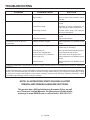
TROUBLESHOOTING
PROBLEM POSSIBLE CAUSE SOLUTION
Engine will not start. On/stop switch is in OFF (O) position.
No fuel.
Fuel valve is closed.
Spark plug faulty, fouled, or
improperly gapped.
Choke lever is in RUN position.
Turn the on/stop switch to ON (I).
Fill fuel tank.
Open fuel valve.
Replace spark plug.
Move choke lever to START position.
Engine lacks power. Fuel element clogged.
Defective pressure unloader.
Check air filter element. Clean or replace
as needed.
Take compressor to a qualified service
center.
Air tank pressure drops when compres-
sor shuts off.
Loose connections (fittings, tubing, etc.).
Loose drain valve.
Pressure unloader leaking.
Check all connections with soap and
water solution and tighten.
Tighten drain valve.
Take compressor to a qualified service
center.
DANGER:
Do not disassemble pressure
unloader, tank drain valves or safety
relief valve with air in tank — bleed
tanks.
MAINTENANCE
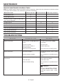
PERIODIC MAINTENANCE SCHEDULE TABLE
NOTE: If a separate engine manual is provided for this air compressor, please follow the maintenance schedule provided
in the engine manual instead of the maintenance information listed below.
Maintenance Items Before each use After first 20 hours After every 100 hours
Check pump oil level X
Check engine oil level X
Check for oil leaks - inspect oil seals, drain
plug, oil plug, sight glass
X
Change pump oil X X
Change engine oil X X
Check/clean engine and pump air filters X
Clean and adjust spark plug and electrodes X
Clean fuel tank inlet screen X
Clean fuel tank outlet filter X
La page charge ...
La page charge ...
La page charge ...
La page charge ...
La page charge ...
La page charge ...
La page charge ...
La page charge ...
La page charge ...
La page charge ...
La page charge ...
La page charge ...
La page charge ...
La page charge ...
La page charge ...
La page charge ...
La page charge ...
La page charge ...
La page charge ...
La page charge ...
La page charge ...
La page charge ...
La page charge ...
La page charge ...
La page charge ...
La page charge ...
La page charge ...
La page charge ...
La page charge ...
La page charge ...
La page charge ...
La page charge ...
La page charge ...
La page charge ...
La page charge ...
La page charge ...
La page charge ...
La page charge ...
La page charge ...
La page charge ...
La page charge ...
La page charge ...
La page charge ...
La page charge ...
La page charge ...
La page charge ...
La page charge ...
La page charge ...
La page charge ...
La page charge ...
La page charge ...
La page charge ...
La page charge ...
La page charge ...
La page charge ...
La page charge ...
-
 1
1
-
 2
2
-
 3
3
-
 4
4
-
 5
5
-
 6
6
-
 7
7
-
 8
8
-
 9
9
-
 10
10
-
 11
11
-
 12
12
-
 13
13
-
 14
14
-
 15
15
-
 16
16
-
 17
17
-
 18
18
-
 19
19
-
 20
20
-
 21
21
-
 22
22
-
 23
23
-
 24
24
-
 25
25
-
 26
26
-
 27
27
-
 28
28
-
 29
29
-
 30
30
-
 31
31
-
 32
32
-
 33
33
-
 34
34
-
 35
35
-
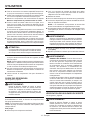 36
36
-
 37
37
-
 38
38
-
 39
39
-
 40
40
-
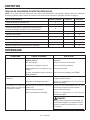 41
41
-
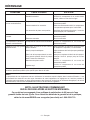 42
42
-
 43
43
-
 44
44
-
 45
45
-
 46
46
-
 47
47
-
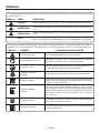 48
48
-
 49
49
-
 50
50
-
 51
51
-
 52
52
-
 53
53
-
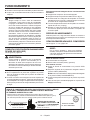 54
54
-
 55
55
-
 56
56
-
 57
57
-
 58
58
-
 59
59
-
 60
60
-
 61
61
-
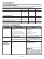 62
62
-
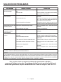 63
63
-
 64
64
-
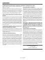 65
65
-
 66
66
-
 67
67
-
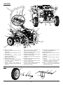 68
68
-
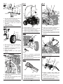 69
69
-
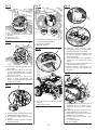 70
70
-
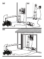 71
71
-
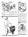 72
72
-
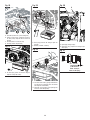 73
73
-
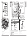 74
74
-
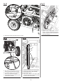 75
75
-
 76
76


RIDGID GP80150RTB Manuel utilisateur
- Catégorie
- Compresseurs d'air
- Taper
- Manuel utilisateur
dans d''autres langues
- English: RIDGID GP80150RTB User manual
- español: RIDGID GP80150RTB Manual de usuario
Documents connexes
-
RIDGID GP80150RT Mode d'emploi
-
-
-
-
-
-
-
-

