Harting 09454001520 Guide d'installation
- Taper
- Guide d'installation

Montageanleitung · Assembly instruction
Instructions d’assemblage
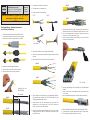
1. Verschraubung und Gehäuse über das Kabel schieben.
1. Push the cable gland and the housing over the cable.
1. Glisser le serre-câble et le corps plastique sur le câble.
2. Kabelmantel und Schirmgeflecht absetzen.
2. Strip the cable jacket and the shielding braid.
2. Dénuder le câble et retirer la tresse de masse.
(Werkzeug · Tool · Outil
0945 800 0002)
15 – 20 mm
45 – 50 mm
SF/ UTP
S/FTP
3. Schirmfolie einschneiden und entfernen.
3. Trim and remove the shielding foil.
3. Entailler et retirer le film de blindage.
S/FTP SF/UTP
10 – 15 mm
4. Adernpaare entdrillen und in die richtige Position biegen.
4. Untwist the single pairs and arrange the wire pairs in the correct
position.
4. Détorsader les paires et les courber dans la bonne position.
SF/ UTP
S/FTP
5. Adern ausformen bis zur Schirmung in den Kabelmanager einführen.
Die Schirmfolie der Adernpaare von S/FTP Kabeln muss bis in den
Zinkdruckgussadernmanager reichen.
5. Insert the wires into the cable manager up to the braid. The
shielding foil of the twisted pairs of the S/FTP cables must
contact the zinc die cast wire manager.
5. Insérer les brins dans le porteur de câble jusqu’à la tresse. Le film de
blindage des paires de câble S/FTP doit être en contact avec le mana-
ger de câble en zinc.
SF/ UTP
S/FTP
6. Überstehende Aderenden bündig so abschneiden, dass keine Kurz-
schlüsse entstehen können. Überstand der Aderenden max. 0,3 mm.
6. Cut the over standing ends of the wires to prevent no electrical
shortcuts. The excess length max. 0,3 mm.
6. Couper les brins qui dépassent afin d’éviter des court-circuits. Maxi-
mum 0,3 mm de dépassement.
87654321 EIA / TIA 568B
7. Kabel mit Adernmanager bis zum Anschlag in das RJ45 Datenmodul
einführen.
7. Insert the cable with the wire manager into the RJ45 data module
up to the end.
7. Insérer complètement le câble avec le porteur dans le module RJ45.
8. Oberes Schirmblech aufsetzen und über den Kabelschirm drücken.
8. Fit and press on the upper shielding shell over the cable screen.
8. Fixer et presser le blindage supérieur sur la tresse.
HARTING Electronics GmbH
P.O. Box 14 73 | D-32339 Espelkamp
Deutsch
English
Français
HARTING RJ Industrial® Gigalink Cat. 6A IP 65/67
Steckverbinder · Connector · Connecteur
www.HARTING.com

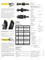
9. Kontakte im RJ45 Datenmodule mit dem HARTING RJ Industrial® Mon-
tagewerkzeug (Bestell-Nr. 09 45 800 0520) verpressen. Achten Sie
darauf, dass das Datenmodule bis zum Anschlag in das Werkzeug ge-
schoben wird.
9. Press the contacts into the RJ45 data module with the HARTING RJ
Industrial® assembly tool (part no. 09 45 800 0520). Make sure to
insert the data module all the way into the assembly tool.
9. Sertir les contacts dans le module RJ45 à l’aide de l’outil de montage
HARTING RJ Indstrial? (Réf. 09 45 800 0520). S’assurer que le module
de données soit bien complètement inséré dans l’outil.
10. Unteres Schirmblech aufsetzen und mit dem oberen Schirmblech mit
einem hörbaren „KLICK“ verrasten.
10. Fit and lock the lower shielding shell over the upper shell with
an audible “click”.
10. Ajuster et encliquer le blindage inférieure sur le blindage supérieur. On
doit entendre un „clic» à l’encliquetage.
11. Steckverbindergehäuse über das montierte Datenmodul schieben
(dazu das Datenmodul ggf. in den RJ45-Halter einlegen) und mit einem
hörbaren „Klick“ verrasten bzw. mit der Dichtschraube fixieren. Beim
Zurückziehen ggf. Symbole am Steckverbinder beachten. Anschlie-
ßend die Kabelverschraubung festziehen.
11. Pull the housing over the installed data module. Use the RJ45
adapter if necessary. Fix the adapter with the screw or snap it
onto the insert with an audible “click”. Please use alignment
symbols, if applicable, to push the hood over the insert until it
snaps into place. Tighten the cable screw.
11. Pousser le capot plastique sur le module de données monté (pour cela,
poser le module de données dans le support de RJ45 si nécessaire) et
l’enclencher avec un «clic» audible ou le fixer avec la vis. En retirant, si
nécessaire, faire attention aux symboles au connecteur. Serrer ensuite
le serre-câble.
Kontaktbelegung
Pin assignment
Répartition des contacts
Kontakt
Pin · Pin EIA / TIA 568 A EIA / TIA 568 B
1
grün / weiß
green / white
vert / blanc
orange / weiß
orange / white
orange / blanc
2 grün · green · vert orange ·orange · orange
3
orange / weiß
orange / white
orange / blanc
grün / weiß
green / white
vert / blanc
4 blau · blue · bleu blau · blue · bleu
5
blau / weiß
blue / white
bleu / blanc
blau / weiß
blue / white
bleu / blanc
6 orange · orange · orange grün · green · vert
7
braun / weiß
brown / white
brun / blanc
braun / weiß
brown / white
brun / blanc
8 braun · brown · brun braun · brown · brun
Technische Kennwerte
Technical data
Données techniques
Übertragungseigenschaften nach Category 6A ISO/IEC11 801:2002 und
EN 50 173-1
Transmission properties in accordance with Category 6A ISO/IEC
11 801:2002 and EN 50 173-1
Caractéristiques de transmission selon catégorie 6A ISO/IEC 11 801:2002
et EN 50 173-1
Schutzart
Degree of protection
Classe de protection IP 65/67
Steckgeometrie RJ45 nach IEC 60 603-7
Mating interface RJ45 in accordance with IEC 60 603-7
Géométrie de connexion RJ45 selon IEC 60 603-7
Aderdurchmesser
Wire diameter
Diamètre de fil max. 1.05 mm
Adernquerschnitt
Wire gauge
Section de cuivre AWG 28-24 flexible
Temperaturbereich
Temperature range
Température de fonctionnement -40 °C ... +70 °C
Kabelmanteldurchmesser
Cable sheath diameter
Diamètre de gaine 6.1 mm – 6.9 mm
Steckzyklen
Mating cycles
Cycle de fonctionnement min. 750
Gehäusematerial: Kunststoff,
schwarz oder Zink-Druckguss
Housing material: Thermoplastic,
black or Zinc, die-cast
Matière du raccord de câble: plastique, noir ou zinc injecté
sous pression
Durchmesser Kabelmantel
Cable diameter
Diamètre de câble
– HARTING PushPull V4
(Kunststoff und Metall)
(plastic and metal)
(plastique et métal): 4.9 - 8.6 mm
– Han® PushPull V14
(Kunststoff · plastic · plastique): 6.5 - 9.5 mm
– Han® PushPull V14
(Metall · metal · métal): 4 - 11 mm
– Han® 3 A (Kunststoff und Metall)
(plastic and metal)
(plastique et métal): 5 - 9 mm
Montageanleitung-Nummer: 09 45 100 1520/99.00 2012-09
Irrtum und technische Änderungen vorbehalten.
Instruction number: 09 45 100 1520/99.00 2012-09
Errors and technical changes excepted.
No. instructions d’assemblage: 09 45 100 1520/99.00 2012-09
Sauf erreur et changements techniques.
-
 1
1
-
 2
2


Harting 09454001520 Guide d'installation
- Taper
- Guide d'installation
dans d''autres langues
Documents connexes
Autres documents
-
Renkforce 12 ports Network patch panel CAT 6A 1 U Le manuel du propriétaire
-
-
-
Lindy 20704 Manuel utilisateur
-
-
-
-
Paso B2080-PG Le manuel du propriétaire
-
Triax 310039 Manuel utilisateur
-
Axis T8123-E Manuel utilisateur