JennAir JES1750ML 30 Inch Electric Downdraft Slide-In Range Le manuel du propriétaire
- Catégorie
- Cuisinières
- Taper
- Le manuel du propriétaire

W11602518A
SLIDE-IN ELECTRIC DOWNDRAFT RANGE OWNER’S
MANUAL
MANUEL D’UTILISATION DE LA CUISINIÈRE
ÉLECTRIQUE ENCASTRÉE À ÉVACUATION PAR LE
BAS
Table of Contents/Table des matières
RANGE SAFETY..............................................................2
Range Safety................................................................2
RANGE MAINTENANCE AND CARE...................................4
Clean Cycle..................................................................4
General Cleaning...........................................................5
INSTALLATION INSTRUCTIONS ........................................6
REQUIREMENTS.............................................................6
Tools and Parts .............................................................6
Location Requirements ...................................................7
Venting Requirements.....................................................9
Electrical Requirements - U.S.A. Only .............................. 11
Electrical Requirements - Canada Only ............................ 11
INSTALLATION ............................................................. 12
Unpack Range ............................................................ 12
Install Anti-Tip Bracket .................................................. 12
Position the Blower Location Template ............................. 13
Install the Downdraft System .......................................... 14
Adjust Leveling Legs .................................................... 15
Level Range ............................................................... 16
Electrical Connection - U.S.A. Only.................................. 16
Install Blower .............................................................. 17
Verify Anti-Tip Bracket Is Installed and Engaged ................. 20
Remove/Replace Drawer (on some models) ...................... 21
Oven Door.................................................................. 21
Complete Installation .................................................... 22
Moving the Range........................................................ 22
SÉCURITÉ DE LA CUISINIÈRE ........................................ 23
Sécurité de la cuisinière ................................................ 23
ENTRETIEN ET RÉPARATION DE LA CUISINIÈRE.............. 26
Programme de nettoyage .............................................. 26
Nettoyage général........................................................ 27
INSTRUCTIONS D’INSTALLATION ................................... 29
SPÉCIFICATIONS .......................................................... 29
Outils et pièces............................................................ 29
Exigences d’emplacement ............................................. 30
Exigences concernant l’évacuation .................................. 32
Spécifications électriques – É.-U. seulement...................... 34
Spécifications électriques – Canada seulement .................. 35
INSTALLATION ............................................................. 35
Déballage de la cuisinière.............................................. 35
Installation de la bride antibasculement ............................ 36
Positionnement du gabarit indiquant l’emplacement du
ventilateur .................................................................. 37
Installation du circuit d’évacuation par le bas...................... 38
Réglage des pieds de nivellement ................................... 39
Réglage de l’aplomb de la cuisinière ................................ 40
Raccordement électrique – É.-U. seulement ...................... 40
Installation du ventilateur ............................................... 42
Vérifier que la bride antibasculement est bien installée et
engagée .................................................................... 44
Enlever/replacer le tiroir (sur certains modèles) .................. 45
Porte du four............................................................... 46
Achever l’installation..................................................... 46
Déplacement de la cuisinière.......................................... 46
IMPORTANT:
Save for local electrical inspector’s use.
IMPORTANT :
À conserver pour consultation par l’inspecteur local des installations électriques

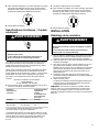
2
RANGE SAFETY
Your safety and the safety of others are very important.
We have provided many important safety messages in this manual and on your appliance. Always read and obey all safety
messages.
This is the safety alert symbol.
This symbol alerts you to potential hazards that can kill or hurt you and others.
All safety messages will follow the safety alert symbol and either the word “DANGER” or “WARNING.” These
words mean:
DANGER You can be killed or seriously injured if you don't
immediately follow instructions.
WARNING You can be killed or seriously injured if you don’t follow
instructions.
All safety messages will tell you what the potential hazard is, tell you how to reduce the chance of injury, and tell you what can
happen if the instructions are not followed.
The range will not tip during normal use. However, the range can tip if you apply too much force or weight to the open door without having
the anti-tip bracket fastened down properly.
WARNING
Tip Over Hazard
A child or adult can tip the range and be killed.
Install anti-tip bracket to floor or wall per installation instructions.
Slide range back so rear range foot is engaged in the slot of the anti-tip bracket.
Re-engage anti-tip bracket if range is moved.
Do not operate range without anti-tip bracket installed and engaged.
Failure to follow these instructions can result in death or serious burns to children and adults.
To verify the anti-tip bracket is properly installed and engaged:
•Slide range forward.
•Look for the anti-tip bracket securely attached to floor or wall.
•Slide range back so rear range foot is under the anti-tip bracket.
•See Installation Instructions for details.
IMPORTANT SAFETY INSTRUCTIONS
WARNING: To reduce the risk of fire, electric shock, or injury to persons when using the appliance, follow basic precautions,
including the following:
�WARNING: TO REDUCE THE RISK OF TIPPING OF
THE RANGE, THE RANGE MUST BE SECURED BY
PROPERLY INSTALLED ANTI-TIP DEVICES. TO CHECK
IF THE DEVICES ARE INSTALLED PROPERLY, SLIDE
RANGE FORWARD, LOOK FOR ANTI-TIP BRACKET
SECURELY ATTACHED TO FLOOR OR WALL, AND
SLIDE RANGE BACK SO REAR RANGE FOOT IS
UNDER ANTI-TIP BRACKET.
�CAUTION: Do not store items of interest to children in
cabinets above an appliance or on the backguard of an
appliance - children climbing on the appliance to reach
items could be seriously injured.
�Never Use Your Appliance for Warming or Heating the
Room.
�Do Not Leave Children Alone - Children should not be left
alone or unattended in area where appliance is in use.
They should never be allowed to sit or stand on any part of
the appliance.
SAVE THESE INSTRUCTIONS

3
IMPORTANT SAFETY INSTRUCTIONS
WARNING: To reduce the risk of fire, electric shock, or injury to persons when using the appliance, follow basic precautions,
including the following:
�Proper Installation - The appliance, when installed, must be
electrically grounded in accordance with local codes, or in
the absence of local codes, with the National Electrical
Code, ANSI/NFPA 70 or the Canadian Electrical Code,
CSA C22.1-02. In Canada, the appliance must be
electrically grounded in accordance with Canadian
Electrical Code. Be sure your appliance is properly installed
and grounded by a qualified technician.
�Wear Proper Apparel – Loose-fitting or hanging garments
should never be worn while using the appliance.
�User Servicing – Do not repair or replace any part of the
appliance unless specifically recommended in the manual.
All other servicing should be referred to a qualified
technician.
�Storage in or on Appliance – Flammable materials should
not be stored in an oven or near surface units.
�This appliance is not intended for storage.
�Do Not Use Water on Grease Fires – Smother fire or flame
or use dry chemical or foam-type extinguisher.
�Do not use replacement parts that have not been
recommended by the manufacturer (e.g. parts made at
home using a 3D printer).
�Use Only Dry Potholders – Moist or damp potholders on hot
surfaces may result in burns from steam. Do not let
potholder touch hot heating elements. Do not use a towel or
other bulky cloth.
�DO NOT TOUCH SURFACE UNITS OR AREAS NEAR
UNITS – Surface units may be hot even though they are
dark in color. Areas near surface units may become hot
enough to cause burns. During and after use, do not touch,
or let clothing or other flammable materials contact surface
units or areas near units until they have had sufficient time
to cool. Among these areas are the coil elements, the
cooktop, and surfaces facing the cooktop.
�Use Proper Pan Size – This appliance is equipped with one
or more surface units of different size. Select utensils
having flat bottoms large enough to cover the surface unit
heating element. The use of undersized utensils will expose
a portion of the heating element to direct contact and may
result in ignition of clothing. Proper relationship of utensil to
burner will also improve efficiency.
�Never Leave Surface Units Unattended at High Heat
Settings – Boilover causes smoking and greasy spillovers
that may ignite.
�Make Sure Reflector Pans or Drip Bowls Are in Place –
Absence of these pans or bowls during cooking may
subject wiring or components underneath to damage.
�Protective Liners – Do not use aluminum foil to line surface
unit drip bowls or oven bottoms, except as suggested in the
manual. Improper installation of these liners may result in a
risk of electric shock, or fire.
�Glazed Cooking Utensils – Only certain types of glass,
glass/ceramic, ceramic, earthenware, or other glazed
utensils are suitable for range-top service without breaking
due to the sudden change in temperature.
�Do Not Cook on Broken Cook-Top – If cook-top should
break, cleaning solutions and spillovers may penetrate the
broken cook-top and create a risk of electric shock. Contact
a qualified technician immediately.
�Utensil Handles Should Be Turned Inward and Not Extend
Over Adjacent Surface Units – To reduce the risk of burns,
ignition of flammable materials, and spillage due to
unintentional contact with the utensil, the handle of a utensil
should be positioned so that it is turned inward, and does
not extend over adjacent surface units.
�Do Not Soak Removable Heating Elements – Heating
elements should never be immersed in water.
�Clean Cooktop With Caution – If a wet sponge or cloth is
used to wipe spills on a hot cooking area, be careful to
avoid steam burn. Some cleaners can produce noxious
fumes if applied to a hot surface.
�Use Care When Opening Door – Let hot air or steam
escape before removing or replacing food.
�Do Not Heat Unopened Food Containers – Build-up of
pressure may cause container to burst and result in injury.
�Keep Oven Vent Ducts Unobstructed.
�Placement of Oven Racks – Always place oven racks in
desired location while oven is cool. If rack must be moved
while oven is hot, do not let potholder contact hot heating
element in oven.
�DO NOT TOUCH HEATING ELEMENTS OR INTERIOR
SURFACES OF OVEN – Heating elements may be hot
even though they are dark in color. Interior surfaces of an
oven become hot enough to cause burns. During and after
use, do not touch, or let clothing or other flammable
materials contact heating elements or interior surfaces of
oven until they have had sufficient time to cool. Other
surfaces of the appliance may become hot enough to cause
burns – among these surfaces are oven vent openings and
surfaces near these openings, oven doors, and windows of
oven doors.
�Care must be taken to prevent aluminum foil and meat
probes from contacting heating elements.
For self-cleaning ranges
�CAUTION: DO NOT LEAVE FOOD OR COOKING
UTENSILS, ETC., IN OVEN DURING THE PYROLYTIC
SELF-CLEANING MODE OF OPERATION.
�Do Not Clean Door Gasket – The door gasket is essential
for a good seal. Care should be taken not to rub, damage,
or move the gasket.
�Do Not Use Oven Cleaners – No commercial oven cleaner
or oven liner protective coating of any kind should be used
in or around any part of the oven.
�Clean Only Parts Listed in Manual.
�Before Self-Cleaning the Oven – Remove broiler pan and
other utensils.
For units with ventilating hood
�Clean Ventilating Hoods Frequently – Grease should not be
allowed to accumulate on hood or filter.
�When flaming foods under the hood, turn the fan on.
For smart enabled ranges and ovens
�Remote operation – This appliance is configurable to allow
remote operation at any time. Do not store any flammable
materials or temperature sensitive items inside, on top or
near surface units of the appliance.
SAVE THESE INSTRUCTIONS

4
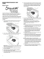
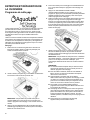
AquaLift®Technology is an innovative cleaning solution that
utilizes heat and water to release baked-on spills from the oven in
less than 1 hour. This new cleaning technology is a low-heat,
odor-free alternative to traditional self-cleaning options.
Allow the oven to cool to room temperature before using the Clean
cycle. If your oven cavity is above 200°F (93°C), it will appear in
the display, and the Clean cycle will not be activated until the oven
cavity cools down.
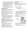
To Clean:
1. Remove all racks and accessories from the oven cavity, and
wipe excess soil. Use a plastic scraper to remove easily
removed soils.
2. Pour 2 cups (16 oz [500 mL]) of distilled or filtered water onto
the bottom of the empty oven, and close the oven door.
IMPORTANT: Do not use chemicals or other additives with the
water. Do not open the oven door during the Clean cycle. The
water on the oven bottom is hot.
3. Press CLEAN/AQUALIFT SELF CLEAN and then START on
the oven control panel.
4. Allow 40 minutes for cleaning and cooldown. A beep will
sound when the Clean cycle is complete.
5. Press OFF/CANCEL/CANCEL UPPER at the end of the cycle.
OFF/CANCEL/CANCEL UPPER may be pressed at any time
to stop the Clean cycle.
6. Remove the residual water and loosened soils with a sponge
or cloth immediately after the Clean cycle is complete. Much
of the initial 2 cups (16 oz [500 mL]) of water will remain in the
oven after the cycle is completed. If additional soils remain,
leave a small amount of water in the oven bottom to assist
with the cleaning.
7. If any soils remain, remove them with a nonscratch scrubbing
sponge or plastic scraper. Additional Clean cycles may be run
to help remove the stubborn soils.
IMPORTANT: Do not use oven cleaners. The use of
chemicals, including commercial oven cleaners or metal
scouring pads, may cause permanent damage to the
porcelain surface of the oven interior.
NOTE:
�The range should be level to ensure that the entire surface
of the bottom of the oven cavity is covered by water at the
beginning of the Clean cycle.
�For best results, use distilled or filtered water. Tap water
may leave mineral deposits on the oven bottom.
�Before removing the residual water and loosened soils at
the end of the Clean cycle, insert a cloth or paper towel
between the lower edge of the oven door and the front
frame to keep water from spilling onto the front of the
range and the floor.
�Soil baked on through several cooking cycles will be more
difficult to remove with the Clean cycle.
�Nonabrasive scrub sponges or eraser-style cleaning pads
(without cleaners) can be effective for cleaning the oven
cavity walls, oven door, and oven bottom for difficult soils.
For best results, moisten the pads and sponges before
use.
�Run an additional Clean cycle for stubborn soils.
�Affresh®Kitchen Appliance Cleaner and affresh®Cooktop
Cleaner may be used to clean the oven bottom, walls, and
door when the oven has finished the cycle and returned to
room temperature. If affresh®Cooktop Cleaner is used, it
is recommended to wipe out the cavity with distilled water
as well. Refer to the Quick Start Guide for ordering
information.
�Additional AquaLift®Technology Cleaning Kits may be
obtained by ordering Part Number W10423113RP. Refer to
the Quick Start Guide for ordering information.
RANGE MAINTENANCE AND
CARE
Clean Cycle

5
General Cleaning
IMPORTANT: Before cleaning, make sure all controls are off and
the oven and cooktop are cool. Always follow label instructions on
cleaning products.
Soap, water, and a soft cloth or sponge are suggested first, unless
otherwise noted.
EXTERIOR PORCELAIN ENAMEL SURFACES (on some
models)
Food spills containing acids, such as vinegar and tomato, should
be cleaned as soon as the entire range is cool. These spills may
affect the finish.
Cleaning Method:
�Glass cleaner, mild liquid cleaner, or nonabrasive scrubbing
pad: Gently clean around the model/serial/rating plate because
scrubbing may remove numbers.
�Affresh®Kitchen and Appliance Cleaner Part Number
W10355010 (not included):
See the Quick Start Guide for contact information.
STAINLESS STEEL (on some models)
NOTE: To avoid damage to stainless steel surfaces, do not use
soap-filled scouring pads, abrasive cleaners, Cooktop Cleaner,
steel-wool pads, gritty washcloths, or abrasive paper towels.
Damage may occur to stainless steel surfaces, even with one-time
or limited use.
Cleaning Method:
Rub in direction of grain to avoid damaging.
�Affresh®Stainless Steel Cleaner Part Number W10355016
(not included):
See the Quick Start Guide for contact information.
METALLIC PAINT (on some models)
Do not use abrasive cleaners, cleaners with bleach, rust
removers, ammonia, or sodium hydroxide (lye) because paint
surface may stain.
CERAMIC GLASS COOKTOP CLEANING
Cleaning Method:
To avoid damaging the cooktop, do not use steel wool, abrasive
powder cleansers, chlorine bleach, rust remover, or ammonia.
1. Remove food/residue with the Cooktop Scraper.
�For best results, use the Cooktop Scraper while the
cooktop is still warm but not hot to the touch. It is
recommended to wear an oven mitt while scraping the
warm cooktop.
�Hold the Cooktop Scraper at approximately a 45° angle
against the glass surface and scrape the residue. It will be
necessary to apply pressure in order to remove the
residue.
Allow the cooktop to cool down completely before proceeding
to Step 2.
2. Apply a few dime-sized drops of Cooktop Cleaner to the
affected areas.
�Rub affresh®Cleaner onto the cooktop surface with the
blue Cooktop Cleaning Pad. Some pressure is needed to
remove stubborn stains.
�Allow the cleaner to dry to a white haze before proceeding
to Step 3.
3. Polish with a clean, dry cloth or a clean, dry paper towel.
�Repeat steps 1 through 3 as necessary for stubborn or
burned-on stains.
The Complete Cooktop Cleaner Kit is available for order
including the following:
�Cooktop Scraper
�Affresh®Cooktop Cleaner
�Blue Cooktop Cleaning Pads
See the Quick Start Guide for ordering information.
CONTROL PANEL AND OVEN DOOR EXTERIOR
To avoid damage to the control panel, do not use abrasive
cleaners, steel-wool pads, gritty washcloths, or abrasive paper
towels.
Cleaning Method:
�Glass cleaner and soft cloth or sponge: Apply glass cleaner to
soft cloth or sponge, not directly on panel.
�Affresh®Kitchen and Appliance Cleaner Part Number
W10355010 (not included):
See the Quick Start Guide for contact information.
OVEN RACKS
Cleaning Method:
�Steel-wool pad
�For racks that have discolored and are harder to slide, a light
coating of vegetable oil applied to the rack guides will help
them slide
�Dishwasher (steam rack water reservoir only, not racks):
Although the water reservoir is durable, it may lose its shine
and/or discolor when washed in a dishwasher

6
BAKING DRAWER (on some models)
Check that baking drawer is cool and empty before cleaning.
Food spills should be cleaned when oven cools. At high
temperatures, foods react with porcelain. Staining, etching, pitting,
or faint white spots can result.
Cleaning Method:
�Mild detergent
OVEN CAVITY
Depending on your model, use AquaLift®Technology or Self-
Clean cycle regularly to clean oven spills.
Do not use oven cleaners
Food spills should be cleaned when oven cools. At high
temperatures, foods react with porcelain. Staining, etching, pitting,
or faint white spots can result.
Cleaning Method:
�Clean cycle: See “Clean Cycle” first.
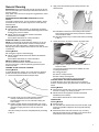
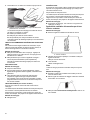
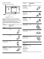
Downdraft ventilation system
Vent Grate
Cleaning Method:
�Lift the vent grate off the cooktop.
A
A. Vent grate
�Nonabrasive plastic scrubbing pad and mildly
abrasive cleanser:
Wipe clean or wash in sink.
�Dishwasher:
Use mild detergent.
Filter
The filter is a permanent type and should be cleaned when soiled.
Cleaning Method:
�Turn off the downdraft ventilation system before removing the
filter.
�Remove vent grate, and then lift the filter out of the vent
chamber.
�Clean the filter in the sink with warm water and detergent or in
the dishwasher.
�Replace the filter.
The filter should always be placed at an angle. As you face the
front of the range, the top of the filter should rest against the
right side of the vent opening. The bottom of the filter should
rest against the left side of the vent chamber at the bottom.
If the filter is flat against the fan wall, ventilation effectiveness
will be reduced.
Ventilation Chamber
The ventilation chamber, which houses the filter, should be
cleaned in the event of spills or when it becomes coated with
a film of grease.
Cleaning Method:
�Mild household detergent or cleanser and paper towel, damp
cloth or sponge:
Apply detergent or cleanser to paper towel, damp cloth
or sponge, not directly to the ventilation chamber.
INSTALLATION INSTRUCTIONS
REQUIREMENTS
Tools and Parts
Gather the required tools and parts before starting installation.
Read and follow the instructions provided with any tools listed
here.
Tools needed
�Tape measure
�Phillips screwdriver
�Flat-blade screwdriver
�1/8" (3.2 mm) flat-blade
screwdriver
�Hand or electric drill
�Level
�Wrench or pliers
�Pipe wrench
�15/16" (2.4 cm) combination
wrench
�1/8" (3.2 mm) drill bit
�Torque Wrench
�Marker or pencil

7
Parts supplied
Check that all parts are included.
�10-32 hex nuts (attached to terminal block) (3)
�Direct wire lugs (3)
�#10 x 15/8" (4.1 cm) screws (for mounting anti-tip bracket) (2)
�Anti-tip bracket (inside oven cavity)
Anti-tip bracket must be securely mounted to the back wall or
floor. Thickness of flooring may require longer screws to
anchor bracket to subfloor. Longer screws are available from
your local hardware store.
Parts Needed
If using a power supply cord kit:
�A UL listed power supply cord kit marked for use with ranges.
The cord should be rated at 250 V minimum, 40 A or 50 A that
is marked for use with nominal 13/8" (3.5 cm) diameter
connection opening and must end in ring terminals or
open-end spade terminals with upturned ends.
�A UL listed strain relief.
Check local codes and existing electrical supply. See the
appropriate “Electrical Requirements” section.
It is recommended that all electrical connections be made by a
licensed, qualified electrical installer.
NOTE: Be sure to purchase only Whirlpool factory-certified parts
and accessories for your appliance. Your installation may require
additional parts. To order, refer to the contact information
referenced in your Quick Start Guide.
Optional Parts
To purchase side trim kits, backsplash kits, or any other
accessories see the Quick Start Guide for ordering information.
NOTE: Be sure to purchase only Whirlpool factory-certified parts
and accessories for your appliance. Your installation may require
additional parts. To order, refer to the contact information
referenced in your Quick Start Guide.
Location Requirements
IMPORTANT: Observe all governing codes and ordinances. Do
not obstruct flow of combustion and ventilation air.
�It is the installer’s responsibility to comply with installation
clearances specified on the model/serial/rating plate. The
model/serial/rating plate is located behind the oven door on the
top right-hand side of the oven frame.
�The range should be located for convenient use in the kitchen.
�To eliminate the risk of burns or fire by reaching over the
heated surface units, cabinet storage space located above the
surface units should be avoided. If cabinet storage is to be
provided, the risk can be reduced by installing a range hood or
microwave hood combination that projects horizontally a
minimum of 5" (12.7 cm) beyond the bottom of the cabinets.
�Recessed installations must provide complete enclosure of the
sides and rear of the range.
�All openings in the wall or floor where range is to be installed
must be sealed.
�Cabinet opening dimensions that are shown must be used.
Given dimensions are minimum clearances.
�The anti-tip bracket must be installed. To install the anti-tip
bracket shipped with the range, see “Install Anti-Tip Bracket”
section.
�Grounded electrical supply is required. See the appropriate
“Electrical Requirements” section.
�Contact a qualified floor covering installer to check that the
floor covering can withstand at least 200°F (93°C).
�Use an insulated pad or 1/4" (6.4 mm) plywood under range if
installing range over carpeting.
IMPORTANT: To avoid damage to your cabinets, check with your
builder or cabinet supplier to make sure that the materials used
will not discolor, delaminate or sustain other damage. This oven
has been designed in accordance with the requirements of UL
and CSA International and complies with the maximum allowable
wood cabinet temperatures of 194°F (90°C).
Mobile Home - Additional Installation
Requirements
The installation of this range must conform to the Manufactured
Home Construction and Safety Standard, Title 24 CFR, Part 3280
(formerly the Federal Standard for Mobile Home Construction and
Safety, Title 24, HUD Part 280). When such standard is not
applicable, use the Standard for Manufactured Home Installations,
ANSI A225.1/NFPA 501A or with local codes.
In Canada, the installation of this range must conform with the
current standards CAN/CSA Z240.1 - latest edition, or with local
codes.
Mobile Home Installations Require:
�When this range is installed in a mobile home, it must be
secured to the floor during transit. Any method of securing the
range is adequate as long as it conforms to the standards
listed above.
�Four-wire power supply cord or cable must be used in a mobile
home installation. The appliance wiring will need to be revised.
See “Electrical Connection - U.S.A. Only” section.

8
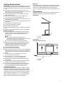
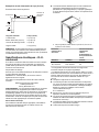
Cabinet Dimensions
Cabinet opening dimensions shown are for 25" (64.0 cm) countertop depth, 24" (61.0 cm) base cabinet depth and 36" (91.4 cm)
countertop height.
IMPORTANT: If installing a range hood or microwave hood combination above the cooking surface, follow the range hood or microwave
hood combination installation instructions for dimensional clearances above the cooktop surface.
NOTE: When installed in a slide-in cutout, the front of oven door may protrude beyond the base cabinet.
Slide-in Cutout Freestanding Cutout
L
A
B
C
D
E
F
M
H
I
J
K
G
J
J
K
G
F
J
H
E
C
B
D
A
I
A. For minimum clearance to top of cooktop, see NOTE*
B. 13" (33 cm) maximum upper cabinet depth
C. 30" (76.2 cm) minimum opening width
D. 18" (45.7 cm) upper side cabinet to countertop
E. 30" (76.5 cm) minimum opening width
F. 5" (12.7 cm) minimum clearance from both sides of range to side wall or
other combustible material
G. The shaded area is recommended for installation of grounded outlet
H. 131/8" (33.3 cm)
I. 711/16" (19.5 cm)
J. 413/16" (12.2 cm)
K. 311/16" (9.4 cm) plus measurement of M
L. Cabinet door or hinges should not extend into the cutout.
M. Remaining counter depth should not exceed 21/4" (5.7 cm)
A. For minimum clearance to top of cooktop, see NOTE*
B. 13" (33 cm) maximum upper cabinet depth
C. 30" (76.2 cm) minimum opening width
D. 18" (45.7 cm) upper side cabinet to countertop
E. 30" (76.2 cm) minimum opening width
F. 5" (12.7 cm) minimum clearance from both sides of range to side wall or
other combustible material
G. The shaded area is recommended for installation of grounded outlet.
H. 131/8" (33.3 cm)
I. 711/16" (19.5 cm)
J. 413/16" (12.2 cm)
K. 311/16" (9.4 cm)
L. Cabinet door or hinges should not extend into the cutout.
NOTE*: 24" (61.0 cm) minimum when bottom of wood or metal cabinet is shielded by not less than 1/4" (6.4 mm) flame retardant
millboard covered with not less than No. 28 MSG sheet steel, 0.015" (0.4 mm) stainless steel, 0.024" (0.6 mm) aluminum or 0.020"
(0.5 mm) copper.
30" (76.2 cm) minimum clearance between the top of the cooking platform and the bottom of an uncovered wood or metal cabinet.

9
Venting Requirements
IMPORTANT: This range must be exhausted outdoors unless you
are using ductless venting. See the “Venting Methods” section.
�Do not terminate the vent system in an attic or other enclosed
area.
�Use an approved vent cap for proper performance. If an
alternate wall or roof cap is used, be certain the cap size is not
reduced and that it has a backdraft damper.
�Vent system must terminate to the outside unless you are
using a ductless vent kit.
�Use a 5" (12.7 cm) or 6" (15.2 cm) round metal vent or a
31/4" x 10" (8.3 cm x 25.4 cm) rectangular vent.
�Rigid metal vent is recommended. For best performance, do
not use plastic or metal foil vent.
�If a joist or stud must be cut, then a supporting frame must be
constructed.
�The size of the vent should be uniform.
�The vent system must have a damper.
�Seal all joints in the vent system.
�Use caulking to seal exterior wall or roof opening around the
cap.
�Determine which venting method is best for your application.
For Best Performance:
�Use 26-gauge minimum galvanized or 25-gauge minimum
aluminum metal vent. Poor quality pipe fittings can reduce
airflow. For external venting, flexible metal vent is not
recommended.
NOTE:
�For external venting, flexible metal vent is not
recommended. Flexible vent creates back pressure and air
turbulence that greatly reduce performance.
�Local codes may require a heavier gauge material.
�Metal duct may be reduced to 30-gauge galvanized steel or
26-gauge aluminized steel if allowed by local codes. This
reduction is based on information in the International
Residential Codes Section M1601.1 (2006 edition).
�Avoid installing 2 elbows together.
�Use no more than three 90° elbows.
�Make sure there is a minimum of 18" (45.7 cm) of straight vent
between the elbows if more than one elbow is used. Elbows
too close together can cause excess turbulence that reduces
airflow.
�Do not use a 5" (12.7 cm) elbow in a 6" (15.2 cm) or
31/4" x 10" (8.3 x 25.4 cm) system.
�Do not reduce to a 5" (12.7 cm) system after using a
6" (15.2 cm) or 31/4" x 10" (8.3 x 25.4 cm) fittings.
�Avoid forming handmade crimps. Handmade crimps may
restrict airflow.
�The length of vent system and number of elbows should be
kept to a minimum to provide efficient performance.
�The maximum equivalent length of the vent system is 60 ft
(18.3 m). For altitudes above 4,500 ft (1272 m), reduce
recommended vent run by 20% for best performance.
Cold Weather Installations
An additional backdraft damper should be installed to minimize
backward cold air flow and a thermal break installed to minimize
conduction of outside temperatures as part of the vent system.
The damper should be on the cold air side of the thermal break.
Order Part Number 708786A for a 5" (12.7 cm) thermal break.
Order Part Number 715557A for a 6" (15.2 cm) thermal break.
Refer to the Quick Start Guide for ordering information.
Makeup Air
Local building codes may require the use of makeup air systems
when using ventilation systems greater than specified CFM of air
movement. The specified CFM varies from locale to locale.
Consult your HVAC professional for specific requirements in your
area.
Venting Methods
Common venting methods are shown for a downdraft range. The
downdraft range may be vented through the wall or floor.
Wall Venting
A
B
A. Wall cap
B. Venting
Floor Venting
Venting Between Floor Joists
A
B
A. Wall cap
B. Venting

10
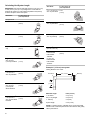
Calculating Vent System Length
IMPORTANT: This range is rated at 60 ft (18.3 m) of 6" (15.2 cm)
or 30 ft (9.15 m) of 5" (12.7 cm) straight duct. To calculate the
length of the system you need, add the equivalent feet (meters)
for each vent piece used in the system.
Vent Piece 5" (12.7 cm) or 6"
(15.2 cm) Round
Straight round
45° elbow 2.5 ft
(0.8 m)
90° elbow 5.0 ft
(1.5 m)
6" (15.2 cm) wall
cap 0.0 ft
(0.0 m)
31/4" x 10" (8.3 cm x
25.4 cm) to 6"
(15.2 cm) transition
4.5 ft
(1.4 m)
6" (15.2 cm) to 31/4"
x 10" (8.3 cm x
25.4 cm) transition
1 ft
(0.3 m)
31/4" x 10" (8.3 cm x
25.4 cm) to 6"
(15.2 cm) 90°
elbow transition
5.0 ft
(1.5 m)
6" (15.2 cm) to 31/4"
x 10" (8.3 cm x
25.4 cm) 90° elbow
transition
5.0 ft
(1.5 m)
Vent Piece 5" (12.7 cm) or 6"
(15.2 cm) Round
31/4" x 10" (8.3 cm x
25.4 cm) 90° elbow 5.0 ft
(1.5 m)
31/4" x 10" (8.3 cm x
25.4 cm) flat elbow 12.0 ft
(3.7 m)
31/4" x 10" (8.3 cm x
25.4 cm) wall cap 0.0 ft
(0.0 m)
Straight 31/4" x 10"
(8.3 cm x 25.4 cm)
5" (12.7 cm)
thermal break
Part Number
708786A
6" (15.2 cm)
thermal break
Part Number
715557A
2.0 ft
(0.6 m)
Example 6" (15.2 cm) vent system
Venting Between Floor Joists
Maximum length = 60 ft (18.3 m)
1- 90° elbow = 5 ft (1.5 m)
8 ft (2.4 m) straight = 8 ft (2.4 m)
1 - wall cap = 0 ft (0 m)
System length = 13 ft (3.9 m)
NOTE: For external venting, a flexible vent is not recommended.
Flexible vents create back pressure and air turbulence that greatly
reduce performance.
Wall cap
6 ft (1.8 m)
90° elbow
2 ft
(0.6 m)

11
Electrical Requirements - U.S.A.
Only
If codes permit and a separate ground wire is used, it is
recommended that a qualified electrical installer determine that
the ground path and wire gauge are in accordance with local
codes.
Do not use an extension cord.
Be sure that the electrical connection and wire size are adequate
and in conformance with the National Electrical Code,
ANSI/ NFPA 70-latest edition and all local codes and ordinances.
A copy of the above code standards can be obtained from:
National Fire Protection Association
1 Batterymarch Park
Quincy, MA 02169-7471
WARNING: Improper connection of the equipment-grounding
conductor can result in a risk of electric shock. Check with a
qualified electrician or service technician if you are in doubt as to
whether the appliance is properly grounded. Do not modify the
power supply cord plug. If it will not fit the outlet, have a proper
outlet installed by a qualified electrician.
Electrical Connection
To properly install your range, you must determine the type of
electrical connection you will be using and follow the instructions
provided for it here.
�Range must be connected to the proper electrical voltage and
frequency as specified on the model/serial/rating plate. The
model/serial/rating plate is located behind the oven door on the
top right-hand side of the oven frame.
A. Model/serial/rating plate (located behind the oven door on the top
right-hand side of the oven frame)
Range Rating* Specified Rating of
Power Supply
Cord Kit and
Circuit Protection
120/240 V 120/208 V Ampere
8.8-16.5 kW 7.8-12.5 kW 40 or 50**
16.6-22.5 kW 12.6-18.5 kW 50
*The NEC calculated load is less than the total connected load
listed on the model/serial/rating plate.
**If connecting to a 50 A circuit, use a 50 A rated cord with kit. For
50 A rated cord kits, use kits that specify use with a nominal 13/8"
(3.5 cm) diameter connection opening.
�A circuit breaker is recommended.
�The range can be connected directly to the circuit breaker box
(or fused disconnect) through flexible or nonmetallic sheathed,
copper or aluminum cable. See the “Electrical Connection -
U.S.A. Only” section.
�Allow at least 6 ft (1.8 m) of slack in the line so that the range
can be moved if servicing is ever necessary.
�A UL listed conduit connector must be provided at each end of
the power supply cable (at the range and at the junction box).
�Wire sizes and connections must conform with the rating of the
range.
�The tech sheet is available online, and the wiring diagram is
located on the back of the range in a plastic bag.
�This range is equipped with a CSA International Certified
Power Cord intended to be plugged into a standard 14-50R
wall receptacle. Be sure the wall receptacle is within reach of
range’s final location.
�Do not use an extension cord.
Electrical Requirements - Canada
Only
WARNING
Electrical Shock Hazard
Electrically ground appliance.
Failure to do so could result in death, fire, or electrical
shock.
If codes permit and a separate ground wire is used, it is
recommended that a qualified electrical installer determine that
the ground path is adequate and wire gauge are in accordance
with local codes.
Be sure that the electrical connection and wire size are adequate
and in conformance with CSA Standard C22.1, Canadian
Electrical Code, Part 1 - latest edition, and all local codes and
ordinances.
A copy of the above code standards can be obtained from:
Canadian Standards Association
178 Rexdale Blvd.
Toronto, ON M9W 1R3 CANADA
�Check with a qualified electrical installer if you are not sure the
range is properly grounded.

12
Range Rating* Specified Rating
of Power Supply
Cord kit and
Circuit Protection
120/240 V 120/208 V Ampere
8.8-16.5 kW 7.8-12.5 kW 40 or 50**
16.6-22.5 kW 12.6-18.5 kW 50
*The NEC calculated load is less than the total connected load
listed on the model/serial/rating plate.
**If connecting to a 50 A circuit, use a 50 A rated cord with kit. For
50 A rated cord kits, use kits that specify use with a nominal 13/8"
(3.5 cm) diameter connection opening.
�A circuit breaker is recommended.
�This range is equipped with a CSA International Certified
Power Cord intended to be plugged into a standard 14-50R
wall receptacle. Be sure the wall receptacle is within reach of
range’s final location.
�Do not use an extension cord.
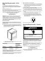
INSTALLATION
Unpack Range
WARNING
Excessive Weight Hazard
Use two or more people to move and install or uninstall
appliance.
Failure to do so can result in back or other injury.
1. Remove shipping materials, tape and film from the range.
Keep cardboard bottom under range. Do not dispose of
anything until the installation is complete.
2. Remove oven racks and parts package from oven and
shipping materials.
3. To remove cardboard bottom, first take 4 cardboard corners
from the carton. Stack one cardboard corner on top of
another. Repeat with the other 2 corners. Place them
lengthwise on the floor behind the range to support the range
when it is laid on its back.
4. Using 2 or more people, firmly grasp the range and gently lay
it on its back on the cardboard corners.
5. Remove cardboard bottom.
The leveling legs can be adjusted while the range is on its
back. See the “Adjust Leveling Legs” section.
NOTE: To place range back up into a standing position, put a
sheet of cardboard or hardboard on the floor in front of range to
protect the flooring. Using 2 or more people, stand range back up
onto the cardboard or hardboard.
Install Anti-Tip Bracket
WARNING
Tip Over Hazard
A child or adult can tip the range and be killed.
Install anti-tip bracket to floor or wall per installation
instructions.
Slide range back so rear range foot is engaged in the
slot of the anti-tip bracket.
Re-engage anti-tip bracket if range is moved.
Do not operate range without anti-tip bracket installed
and engaged.
Failure to follow these instructions can result in death or
serious burns to children and adults.
1. Remove the anti-tip bracket from the inside of the oven.
2. Determine which mounting method to use: floor or wall.
If you have a stone or masonry floor, you can use the wall
mounting method. If you are installing the range in a mobile
home, you must secure the range to the floor.
This anti-tip bracket and screws can be used with wood or
metal studs.
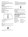
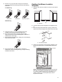
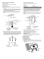
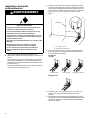
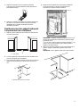
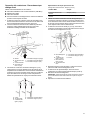
3. Determine and mark centerline of the cutout space. The
mounting bracket can be installed on either the left-hand or
right-hand side of the cutout. Position mounting bracket
against the wall in the cutout so that the V-notch of the bracket
is 121/2" (31.8 cm) from centerline, as shown.
Centerline
B
A
A. 121/2" (31.8 cm)
B. Bracket V-notch

13
4. Drill two 1/8" (3 mm) holes that correspond to the bracket
holes of the determined mounting method. See the following
illustrations.
Floor Mounting
Rear position Front position Diagonal (2 options)
Wall Mounting
5. Using the two #10 x 15/8" (4.1 cm) Phillips-head screws
provided, mount anti-tip bracket to the wall or floor.
6. Move range close enough to opening to allow for final
electrical connections. Remove shipping base, cardboard, or
hardboard from under range.
7. Move range into its final location, making sure rear leveling leg
slides into anti-tip bracket.
8. Move range forward onto shipping base, cardboard or
hardboard to continue installing the range, using the following
installation instructions.
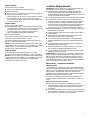
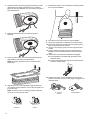
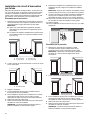
Position the Blower Location
Template
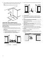
1. Determine and mark the centerline on the floor of the cabinet
opening.
A
A. Centerline
2. Locate the blower location template in the Installation Parts
Kit.
3. If the countertop extends behind the opening, measure the
distance from the back edge of the cabinet cutout to the wall.
A
A. Countertop Filler Depth
4. Fold the top of the blower mounting/venting template on the
line that corresponds to the countertop depth measured in
Step 3.
Le montage du ventilateur doit être fait dans cette zone
RETIRER LE GABARIT AVANT DE FINALISER L'INSTALLATION
GABARIT D'INSTALLATION D'UN SYSTÈME DE VENTILATION À ASPIRATION DESCENDANTE
Numéro de la pièce W10765779B
© 2015. Tous droits réservés.
No Rear
Countertop
Filler Fold Here
Pas de
bouche-fente pour
comptoir arrière pour
replier ici
Fold On Line Based On
Countertop Filler Depth
Measurement
Replier sur la ligne en
fonction de la mesure de
profondeur du bouche-fente
pour comptoir
Le montage du ventilateur doit être fait dans cette zone
Part Number W10765779B
© 2015. All rights reserved.
NOTE: The template has lines every 1/4" (6.4 mm) from the
back edge. If the distance measured in the previous step is
11/4" (32 mm), fold the template on the line labeled 11/4"
(32 mm). If there is no countertop filler depth, fold the
template at zero depth.
Fold Here

14
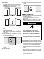
5. Align the template centerline with the centerline marked on the
floor. Align the folded edge of the template against the rear
wall.
NOTE: Secure the template to the floor with tape.
Install the Downdraft System
Determine which venting method to use: floor or rear wall venting.
Go to the section for your type of venting. Consider the location of
all utilities and ducts prior to determining final position to ensure
proper fit and location.
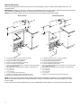
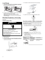
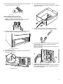
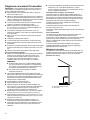
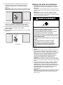
Rear Wall Venting
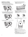
1. Determine where within area illustrated below the vent will
exit. Mark the vent hole for the type of venting you are using.
IMPORTANT:
�Check for obstructions (plumbing, electrical, wall studs,
etc.) before marking the vent hole location.
�The home venting system should terminate within the
defined area using 5" (12.7 cm) round venting.
AC
D
B
A. 12" (30.5 cm)
B. 71/2" (19 cm) C. 8" (20.3 cm)
D. 51/2" (14 cm)
2. Draw an outline of the vent on the wall and cut the vent hole.
A
A. Vent hole
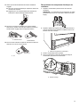
3. Locate the blower.
4. Locate the blower outlet adapter in the installation parts kit.
5. Install the blower outlet adapter to the blower vent using three
8-18 x 3/8" screws. Seal the connection with aluminum foil
tape.
6. Remove three felt pads from the gasket strip.
7. Remove the paper backing from the felt pads and apply to the
bottom of blower motor tabs.
NOTE: Felt pads reduce motor noise and aid in mounting to
uneven floors.
8. Position the blower on the template so that the blower outlet
adapter aligns with the home venting.
IMPORTANT: Make sure the blower motor is positioned within
the area as shown on the template.
9. Connect the home vent system to the blower outlet adapter
using sheet metal screws. Seal the connection with aluminum
foil tape.
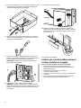
10. Drill three 1/8 " (3 mm) pilot holes using the holes in the
blower motor tabs as guides.
11. Remove the template.
12. Mount the blower motor to the floor with three #10 x 1" screws
provided.

15
Floor Venting
1. Determine where within the template area that the vent will
exit. Mark the vent hole for the type of venting you are using.
IMPORTANT: Check for obstructions (plumbing, electrical,
etc.) before marking the vent hole location.
2. Draw and cut the vent hole in the floor.
3. Install the blower outlet adapter to the blower vent using three
8-18 x 3/8" screws. Seal the connection with aluminum foil
tape.
4. Remove three felt pads from the gasket strip.
5. Remove the paper backing from the felt pads and apply the
bottom of a blower motor tabs.
NOTE: Felt pads reduce motor noise and aid in mounting to
uneven floors.
6. Position the blower motor in the cabinet opening so that the
blower exhaust venting aligns with the vent hole cut in Step 2.
IMPORTANT: Make sure the blower motor is positioned within
the area as shown on the template.
7. Connect the house vent system to the blower outlet adapter
using a vent clamp; then wrap connection with aluminum tape.
8. Drill three 1/8" (3 mm) pilot holes using the blower motor tabs
as guides.
9. Remove the template.
10. Mount the blower motor to the floor with three #10 x 1" screws
provided.
Top View
Adjust Leveling Legs
1. If range height adjustment is necessary, use a wrench or pliers
to loosen the 4 leveling legs.
This may be done with the range on its back or with the range
supported on 2 legs after the range has been placed back to a
standing position.
NOTE:To place range back up into a standing position, put a sheet of
cardboard or hardboard in front of range. Using 2 or more people,
stand range back up onto the cardboard or hardboard.
WARNING
Tip Over Hazard
A child or adult can tip the range and be killed.
Install anti-tip bracket to floor or wall per installation
instructions.
Slide range back so rear range foot is engaged in the
slot of the anti-tip bracket.
Re-engage anti-tip bracket if range is moved.
Do not operate range without anti-tip bracket installed
and engaged.
Failure to follow these instructions can result in death or
serious burns to children and adults.
2. Measure the distance from the top of the counter to the floor.
3. Measure the distance from the top of the cooktop to the bottom
of the leveling legs. This distance should be the same. If it is
not, adjust the leveling legs to the correct height. The leveling
legs can be loosened to add up to a maximum of 1" (2.5 cm). A
minimum of 3/16" (5 mm) is needed to engage the anti-tip
bracket.
NOTE:If height adjustment is made when range is standing, tilt the
range back to adjust the front legs, and then tilt forward to adjust the
rear legs.
4. When the range is at the correct height, check that there is
adequate clearance under the range for the anti-tip bracket.
Before sliding range into its final location, check that the anti-
tip bracket will slide under the range and onto the rear leveling
leg prior to anti-tip bracket installation.
NOTE:If a Trim Kit will be used, the top of the cooktop should be
higher than the counter. See the Installation Instructions included with
the Trim Kit for the correct height.

16
Level Range
1. Place level on the oven bottom, as indicated in one of the two
figures below, depending on the size of the level. Check with
the level side to side and front to back.
2. If range is not level, use a wrench or pliers to adjust leveling
legs up or down until the range is level.
NOTE: Range must be level for satisfactory baking
performance and best cleaning results using AquaLift®Self-
Clean Technology.
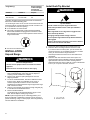
Electrical Connection - U.S.A. Only
If your home has a 4-wire direct connection, go to “Install Using
Direct Wire”.
Install Using Direct Wire
WARNING
Electrical Shock Hazard
Disconnect power before servicing.
Use 8 gauge copper or 6 gauge aluminum wire.
Electrically ground range.
Failure to follow these instructions can result in death,
fire, or electrical shock.
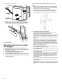
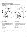
Direct Wire Strain Relief
1. Disconnect power.
2. Remove the lower access cover screws located on the back of
the range. Pull the bottom of the cover toward you and out to
remove cover from range.
A
B
C
A. Mounting tabs (3)
B. Lower access cover
C. Screws (2)
3. Assemble a UL listed conduit connector in the opening.
A
B
A. Removable retaining nut
B. Conduit
4. Tighten strain relief screw against the flexible conduit.
Direct Wire Installation: Copper or Aluminum Wire
This range may be connected directly to the fuse disconnect or
circuit breaker box. Depending on your electrical supply, make the
required 4-wire connection.
1. Strip outer covering back 3" (7.6 cm) to expose wires. Strip
the insulation back 3/8" (1.0 cm) from the end of each wire.
2. Allow enough slack in the wire to easily attach the wiring
terminal block.
3. Complete installation following instructions for your type of
electrical connection:
4-wire (recommended)
Electrical Connection Options
Electrical
Connection Options And you will be
connecting to: Go to Section:
4-wire direct A circuit breaker
box or fused
disconnect
4-Wire Connection:
Direct Wire
(7.6 cm)
3"
1.0 cm
3/8"
3/8"
(1.0 cm)
(12.7 cm)
5"

17
4-Wire Connection: Direct Wire
Use this method for:
�New branch-circuit installations (1996 NEC)
�Mobile homes
�Recreational vehicles
�In an area where local codes prohibit grounding through the
neutral
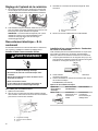
1. Use a Phillips screwdriver to remove the ground-link screw
from the back of the range. Save the ground-link screw and the
end of the ground link under the screw.
2. Pull the wires through the strain relief on bottom of range.
Allow enough slack to easily attach wiring to the terminal
block.
A
B
D
F
E
G
c
A. Terminal block
B. Ground-link screw
C. Cord/conduit
D. Bare (green)
ground wire
E. Line 2 (red) wire
F. Nautral (white) wire
G. Line 1 (black) wire
3. Attach terminal lugs to line 1 (black), neutral (white), and line 2
(red) wires. Loosen (do not remove) the setscrew on the front
of the terminal lug and insert exposed wire end through bottom
of terminal lugs. Securely tighten setscrew to torque as shown
in the following Bare Wire Torque Specifications chart.
A
B
CDE
A. Terminal lug
B. Setscrew
C. Line 2 (red) wire
D. Natural (white) wire
E. Line 1 (black) wire
Bare Wire Torque Specifications
Attaching terminal lugs to the terminal block - 20 lbs-in
(2.3 N-m).
Wire Awg Torque
8 gauge copper 25 lbs-in (2.8 N-m)
6 gauge aluminium 35 lbs-in (4.0 N-m)
4. Use a hex or Phillips screwdriver to connect the bare (green)
ground wire to the range with the ground-link screw and
ground-link section. The ground wire must be attached over
the ground-link section and must not contact any other
terminal.
5. Use 3/8" (1.0 cm) nut driver to connect the neutral (white) wire
to the center terminal block post with one of the 10-32 hex
nuts.
A
B
C
DE
F
G
A. 10-32 hex nut
B. Line 2 (red) wire
C. Bare (green)
ground wire
D. Ground-link screw
E. Neutral (white) wire
F. Line 1 (black) wire
G. Terminal lug
6. Connect line 2 (red) and line 1 (black) wires to the outer
terminal block posts with 10-32 hex nuts.
7. Using a torque wrench, tighten the hex nuts to a
recommended torque of 20 in-lbs (2.3 N-m).
8. Firmly tighten hex nuts.
IMPORTANT:Verify the tightness of the hex nuts. Ensure all
harnesses are tightened to the terminal block and are not loose.
9. Replace lower access cover.
Install Blower
Install Blower Cover
1. Locate blower motor cover.
2. Run the blower motor wires with strain relief through the small
opening in the blower motor cover, starting from the inside and
feeding out.
Strain relief

18
3. Feed blower motor wire through opening and place the strain
relief bracket to the inside of the blower cover. Install and
tighten the two (2) provided #8–18 x 3/8" screws to secure the
strain relief bracket.
4. Reposition the blower motor cover retainer spring as
illustrated.
5. Remove paper from the rear of the rectangular felt pad and
apply adhesive side of felt to the bellow flange.
NOTE: This step is important to ensure maximum blower
performance.
6. Apply blower motor cover to the blower. Slightly spread the
cover retainer spring to allow the cover to drop into position on
the blower motor.
NOTE: The blower motor cover will not properly install if the
motor wire is on the top of the motor.
Incorrect correct
7. Rotate blower motor cover so the bellows are facing towards
the front of the installation.
8. Move blower motor wire to the front of the installation.
9. Remove the cardboard or hardboard from under the range.
10. Remove the front lower access panel of the range by gently
lifting on the panel then pull outward.
11. Using 2 or more people, gently move the range into its final
location.
12. Check to ensure the electrical cord are not kinked. Use a
flashlight to look underneath the bottom of and behind the
range.
13. Verify that the anti-tip bracket is installed and engaged.
�Use a flashlight to look underneath the bottom of and
behind the range.
�Visually check that the rear range foot is inserted into the
slot of the anti-tip bracket.
14. Rotate blower motor cover so the bellows are in their final
position. Ensure the rear of the bellow flange is engaged in the
retaining bracket.
A
A. Retaining
bracket Final Position

19
15. Secure the front of the blower bellow flange to the range frame
with the supplied #8–18 x 3/8" screw.
A
A. Screw
Connect Blower Electrical Parts
1. Locate the capacitor (in Blower Motor Kit).
NOTE: The capacitor is supplied with a small harness that
terminates in a two-pin connector as shown.
Post 1 Post 2
2. Locate the capacitor storage tray in front of the blower bellow
connection point in the lower right side of the range.
A
A. Capacitor storage tray
3. Place capacitor in tray.
4. Secure the capacitor with the capacitor retention bracket, then
install the bracket screw.
A
A. Retention bracket
5. Secure the blower motor strain relief, near the quick
connection end, to the blower electrical terminal cover with the
two provided screws.
6. Locate the two-pin connector on the blower motor wire
harness and connect it to the two-pin capacitor connector.
7. Locate the 4-pin connector on the blower motor wire and plug
it into the terminal connection point directly behind the
capacitor storage tray.
NOTE: The terminal release (clip point) will be facing toward
the front of the range.
8. Install blower electrical terminal cover.
NOTE: When replacing cover, insert the terminal cover tabs in
the corresponding slots in the range, and push the terminal
cover rearward to engage.

20
9. Install terminal cover screw.
3
2
1
10. Replace the access panel by aligning the studs with the
keyhole slots on the range. Press the access panel forward
into the slots and push downward to engage the studs.
1
2
11. Reconnect power.
Verify Anti-Tip Bracket Is Installed
and Engaged
On Ranges Equipped with a Premium Storage Drawer:
1. Slide range into final location, making sure rear leveling leg
slides into anti-tip bracket.
2. Remove the premium storage drawer. See the
“Remove/ Replace Drawer” section.
3. Use a flashlight to look underneath the bottom of the range.
4. Visually check that the rear range foot is inserted into the slot
of the anti-tip bracket.
On Ranges Equipped with a Warming Drawer or Baking
Drawer:
1. Slide range into final location, making sure rear leveling leg
slides into anti-tip bracket. Leave a 1" (2.5 cm) gap between
the back of the range and the back wall.
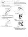
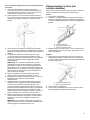
2. Place the outside of your foot against the bottom front of the
warming drawer or baking drawer to keep the range from
moving, and then grasp the back of the range, as shown.
3. Slowly attempt to tilt the range forward.
If you encounter immediate resistance, the range foot is
engaged in the anti-tip bracket. Go to Step 8.
4. If the rear of the range lifts more than 1/2" (1.3 cm) off the floor
without resistance, stop tilting the range and lower it gently
back to the floor. The range foot is not engaged in the anti-tip
bracket.
IMPORTANT: If there is a snapping or popping sound when
lifting the range, the range may not be fully engaged in the
bracket. Check to see if there are obstructions keeping the
range from sliding to the wall or keeping the range foot from
sliding into the bracket. Verify that the bracket is held securely
in place by the mounting screws.
5. Slide the range forward, and verify that the anti-tip bracket is
securely attached to the floor or wall.
6. Slide range back so the rear range foot is inserted into the slot
of the anti-tip bracket.
7. Repeat steps 1 and 2 to ensure that the range foot is engaged
in the anti-tip bracket.
If the rear of the range lifts more than 1/2" (1.3 cm) off the floor
without resistance, the anti-tip bracket may not be installed
correctly. Do not operate the range without anti-tip bracket
installed and engaged. Please reference the “Warranty” to
contact service.
8. Move the range into its final location. Check that the range is
level by placing a level on the oven bottom. See the “Level
Range” section.
IMPORTANT: If the range is moved to adjust the leveling legs,
verify that the anti-tip bracket is engaged by repeating steps 1
to 8.
La page est en cours de chargement...
La page est en cours de chargement...
La page est en cours de chargement...
La page est en cours de chargement...
La page est en cours de chargement...
La page est en cours de chargement...
La page est en cours de chargement...
La page est en cours de chargement...
La page est en cours de chargement...
La page est en cours de chargement...
La page est en cours de chargement...
La page est en cours de chargement...
La page est en cours de chargement...
La page est en cours de chargement...
La page est en cours de chargement...
La page est en cours de chargement...
La page est en cours de chargement...
La page est en cours de chargement...
La page est en cours de chargement...
La page est en cours de chargement...
La page est en cours de chargement...
La page est en cours de chargement...
La page est en cours de chargement...
La page est en cours de chargement...
La page est en cours de chargement...
La page est en cours de chargement...
La page est en cours de chargement...
La page est en cours de chargement...
-
 1
1
-
 2
2
-
 3
3
-
 4
4
-
 5
5
-
 6
6
-
 7
7
-
 8
8
-
 9
9
-
 10
10
-
 11
11
-
 12
12
-
 13
13
-
 14
14
-
 15
15
-
 16
16
-
 17
17
-
 18
18
-
 19
19
-
 20
20
-
 21
21
-
 22
22
-
 23
23
-
 24
24
-
 25
25
-
 26
26
-
 27
27
-
 28
28
-
 29
29
-
 30
30
-
 31
31
-
 32
32
-
 33
33
-
 34
34
-
 35
35
-
 36
36
-
 37
37
-
 38
38
-
 39
39
-
 40
40
-
 41
41
-
 42
42
-
 43
43
-
 44
44
-
 45
45
-
 46
46
-
 47
47
-
 48
48


JennAir JES1750ML 30 Inch Electric Downdraft Slide-In Range Le manuel du propriétaire
- Catégorie
- Cuisinières
- Taper
- Le manuel du propriétaire
dans d''autres langues
Documents connexes
Autres documents
-
KitchenAid KSEB900ESS Manuel utilisateur
-
-
KitchenAid W11652320A Le manuel du propriétaire
-
Whirlpool WFE775H0HZ Mode d'emploi
-
Jenn-Air JDS1750FB Mode d'emploi
-
KitchenAid W10750372A Manuel utilisateur
-
Maytag ELECTRIC RANGE User Instructions
-
Whirlpool WFI910H0AS Le manuel du propriétaire
-
KitchenAid KSIB900ESS Le manuel du propriétaire
-
Midea MER30B12AWWC Manuel utilisateur