Ultra-Aire MD33 Installation Instructions Manual
- Taper
- Installation Instructions Manual
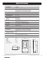
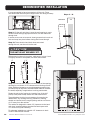
Vous trouverez ci-dessous de brèves informations pour le Déshumidificateur Ultra-Aire MD33. Cet appareil de déshumidification intégré est conçu pour être installé à l'intérieur d'une ossature murale standard. Il offre un confort optimal, une meilleure santé et une protection accrue de vos biens. Il est équipé d'une commande numérique, d'un filtre lavable et d'un tuyau de drainage de 10 pieds. Le déshumidificateur est conçu pour une installation murale et nécessite une alimentation électrique de 120 volts.
Vous trouverez ci-dessous de brèves informations pour le Déshumidificateur Ultra-Aire MD33. Cet appareil de déshumidification intégré est conçu pour être installé à l'intérieur d'une ossature murale standard. Il offre un confort optimal, une meilleure santé et une protection accrue de vos biens. Il est équipé d'une commande numérique, d'un filtre lavable et d'un tuyau de drainage de 10 pieds. Le déshumidificateur est conçu pour une installation murale et nécessite une alimentation électrique de 120 volts.


-
 1
1
-
 2
2
-
 3
3
-
 4
4
-
 5
5
-
 6
6
-
 7
7
-
 8
8
-
 9
9
-
 10
10
-
 11
11
-
 12
12
-
 13
13
-
 14
14
-
 15
15
-
 16
16
-
 17
17
-
 18
18
-
 19
19
-
 20
20


Ultra-Aire MD33 Installation Instructions Manual
- Taper
- Installation Instructions Manual
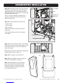
Vous trouverez ci-dessous de brèves informations pour le Déshumidificateur Ultra-Aire MD33. Cet appareil de déshumidification intégré est conçu pour être installé à l'intérieur d'une ossature murale standard. Il offre un confort optimal, une meilleure santé et une protection accrue de vos biens. Il est équipé d'une commande numérique, d'un filtre lavable et d'un tuyau de drainage de 10 pieds. Le déshumidificateur est conçu pour une installation murale et nécessite une alimentation électrique de 120 volts.
dans d''autres langues
- English: Ultra-Aire MD33
Autres documents
-
Broan NuTone B33DHW Manuel utilisateur
-
Phoenix DryMAX XL Guide de démarrage rapide
-
-
-
Honeywell Dehumidifier DR90 Manuel utilisateur
-
Fedders A7DH45B2A Mode d'emploi
-
-
Maytag 23-11-2233N-008 Manuel utilisateur
-
-
 Therma-Stor Phoenix CAM Pro Le manuel du propriétaire
