
DANBY PRODUCTS LIMITED, ONTARIO, CANADA N1H 6Z9
DANBY PRODUCTS INC., FINDLAY, OHIO, USA 45840
OWNER’S MANUAL
MANUEL DU PROPRIÉTAIRE
MANUAL DEL PROPIETARIO
www.Danby.com
*
*
AIR CONDITIONER
Owner’s Manual.............................1 - 26
CLIMATISEUR
Manuel du propriétaire.................27 - 52
AIRE ACONDICIONADO
Manual del propietario.................53 - 78
MODEL * MODÈLE * MODELO
DAC080B6IWDB-6
DAC100B6IWDB-6
DAC120B6IWDB-6
2021.02.26

1
Welcome to the Danby family.
We are proud of our quality products and we believe in dependable service. We suggest
that you read this owner’s manual before plugging in your new appliance as it contains
important operation information, safety information, troubleshooting, and maintenance tips
to ensure the reliability and longevity of your appliance.
You are entitled to the warranty coverage as described in the owner’s manual provided with
your new appliance.
1. Please write down your appliance information below. You must keep the original proof
of purchase receipt to validate and receive warranty services.
2. Register your product online and receive a FREE 2 MONTH WARRANTY EXTENSION
after fi lling out a product survey, at www.danby.com/support/product-registration/
Need Help?
1. Read your Owner’s Manual for installation help, troubleshooting, and maintenance
assistance.
2. Visit www.Danby.com to access self-service tools, FAQs and much more by searching
your model number in the search bar.
3. For the Quickest Customer Service, please fi ll out the web form at www.danby.com/
support. Your submission will go directly to an expert on your particular appliance.
Our average response times are between 20 minutes and 2 hours, during EST business
hours.
4. Call 1-800-263-2629 - please note that during peak hours, hold times can exceed one
hour.
Model Number: ____________________________________________________
Serial Number: ____________________________________________________
Date of Purchase: __________________________________________________

Important Safety Information
READ AND FOLLOW ALL SAFETY INSTRUCTIONS
SAVE THESE INSTRUCTIONS!
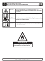
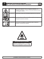
CAUTION: RISK OF FIRE
Flammable refrigerant used. When maintaining
or disposing of the air conditioner, the refrigerant
must not be allowed to vent into the open air.
WARNING Shows that the appliance uses a fl ammable refrigerant. If the
refrigerant leaks and is exposed to an external ignition source, there is
a risk of fi re.
CAUTION Shows that the operation manual should be read carefully.
CAUTION Shows that service personnel should be handling this equipment with
reference to the installation manual.
CAUTION Shows that the information is available such as the operating manual
or the installation manual.

SAVE THESE INSTRUCTIONS!
Important Safety Information
READ AND FOLLOW ALL SAFETY INSTRUCTIONS
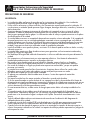
SAFETY PRECAUTIONS
WARNING
• Installation must be performed according to the installation instructions. Improper installation can cause
water leakage, electrical shock or fi re.
• Use only the included accessories and parts and specifi ed tools for the installation. Using non-standard
parts can cause water leakage, electrical shock, fi re and injury or property damage.
• Make sure that the outlet you are using is grounded and has the appropriate voltage. The power cord
is equipped with a three-prong grounding plug to protect against shock. Voltage information can be
found on the nameplate of the unit.
• You unit must be used in a properly grounded wall receptacle. if the wall receptacle you intend to use is
not adequately grounded or protected by a time delay fuse or circuit breaker (the fuse of circuit breaker
needed is determined by the maximum current of the unit. The maximum current is indicated on the
nameplate located on the unit), have a qualifi ed electrician install the proper receptacle.
• Install the unit on a fl at, sturdy surface. Failure to do so could result in damage or excessive noise and
vibration.
• The unit must be kept free from obstruction to ensure proper function and to mitigate safety hazards.
• Do not modify the length of the power cord or use an extension cord to power the unit.
• Do not share a single outlet with other electrical appliances. Improper power supply can cause fi re or
electrical shock.
• Do not install you air conditioner in a wet room such as a bathroom or laundry room. Too much
exposure to water can cause electrical components to short circuit.
• Do not install the unit in a location that may be exposed to combustible fas as this could cause fi re.
• The unit has wheels to facilitate moving. Make sure not to use the wheels on thick carpet or to roll over
objects as this could cause tipping.
• Do not operate a unit that been dropped or damaged.
• The appliance with the electric heater shall have at least 1 meter space from combustible materials.
• Do not touch the unit with wet or damp hands or when barefoot.
• If the air conditioner is knocked over during use, turn off the unit and unplug it from the main power
supply immediately. Visually inspect the unit to ensure there is no damage. If you suspect the unit has
been damaged contact a technician or customer service for assistance.
• In a thunderstorm, the power must be cut off to avoid damage to the machine due to lightning.
• You air conditioner should be used in such a way that it is protected from moisture. e.g. condensation,
splashed water, etc. Do not place or store you air conditioner where it can fall or be pulled into water
or any other liquid. Unplug immediately if this occurs.
• All wiring must be performed strictly in accordance with the wiring diagram location inside the unit.
• The units circuit board (PCB) is designed with a fuse to provide over current protection. The
specifi cations of the fuse are printed on the circuit board.
• When the water drainage function is not in use keep the upper and lower drain plugs fi rmly installed in
the unit. The drain plugs can be a choking hazard to children.

Important Safety Information
READ AND FOLLOW ALL SAFETY INSTRUCTIONS
SAVE THESE INSTRUCTIONS!
CAUTION
• This appliance is not intended for use by persons (including children) whose physical, sensory or
mental capabilities may be different or reduced, or who lack experience or knowledge, unless such
persons receive supervision or training to operate the appliance by a person responsible for their
safety. Children should be supervised to ensure that they do not play with the appliance. Children must
be supervised around the unit at all times.
• If the power supply cord is damaged it must be replaced by the manufacturer, its service agent or
similarly qualifi ed persons in order to avoid a hazard.
• Prior to cleaning or other maintenance, the appliance must be disconnected from the power supply.
• Do not remove any fi xed covers. Never use this appliance if it is not working properly or if it has been
dropped or damaged.
• Do not run cord under carpeting. Do not cover cord with throw rugs, runners or similar coverings. Do
not route cord under furniture or appliances. Arrange cords away from traffi c and where it will not be
tripped over.
• Do not operate a unit with a damaged power cord, plug, power fuse or circuit breaker. Discard the unit
or return to an authorized service facility for examination and/or repair.
• To reduce the risk of fi re or electric shock do not use this air conditioner with any solid-state speed
control device.
• The appliance shall be installed in accordance with national wiring regulations.
• Contact the authorized service technician for repair or maintenance of this unit.
• Contact the authorized service installer for installation of this unit.
• Do not cover or obstruct the inlet or outlet grilles.
• Do not use this product for functions other than those described in this instruction manual.
• Before cleaning turn off the power and unplug the unit.
• Disconnect the power if strange sounds, smells or smoke comes from it.
• Do not press the buttons on the control panel with anything other than your fi ngers.
• Do not remove any fi xed covers. Never use this appliance if it is not working properly or if it has been
dropped or damaged.
• Do not operate or stop the unit by inserting or pulling out the power cord plug.
• Do not use hazardous chemicals to clean or come into contact with the unit. Do not use the unit in the
presence of infl ammable substances or vapour such as alcohol, insecticides, petrol, etc.
• Always transport your air conditioner in a vertical position and stand on a stable, level surface during
use.
• Always contact a qualifi ed person to carry out repairs. If the damaged power supply cord must be
replaced with a new power supply cord obtained from the product manufacturer and not repaired.
• Hold the plug by the head of the power plug when removing it.
• Turn off the appliance when not in use.

Important Safety Information
READ AND FOLLOW ALL SAFETY INSTRUCTIONS
SAVE THESE INSTRUCTIONS!
Note about fl uorinated gasses
• Fluorinated greenhouse gases are contained in hermetically sealed equipment. For specifi c information
on the type, the amount and the C02 equivalent in tonnes of the fl uorinated greenhouse gas on some
models. Please refer to the relevant label on the unit itself.
• Installation, service, maintenance and repair of this unit must be performed by a certifi ed technician.
• Product installation and recycling must be performed by a certifi ed technician.
WARNING for using R32 refrigerant
• Do not use means to accelerate the defrosting process or to clean other than those recommended by the
manufacturer.
• The appliance shall be stored in a room without continuously operating ignition sources for example,
open fl ames, an operating gas appliance or an operating electric heater.
• Do not pierce or burn.
• Be aware that the refrigerants may not contain an odour.
• The appliance should be installed, operated and stored in a room with a fl oor area according to the
amount of refrigerant to be charged. For specifi c information on the type of gas and the amount,
please refer to the relevant label on the unit itself. When there are differences between the label and the
manual on the minimum room area description, the description on the label shall prevail.
• Compliance with national gas regulations shall be observed.
• Keep ventilation openings clear of obstruction.
• The appliance shall be stored so as to prevent mechanical damage from occurring.
• A warning that the appliance shall be stored in a well-ventilated area where the room size corresponds
to the room area as specifi ed for operation.
• Any person involved with working on the refrigerant circuit should hold a current, valid certifi cate from
an industry accredited assessment authority which authorizes their competence to handle refrigerants
safely in accordance with an industry recognized assessment specifi cation.
• Servicing shall only be performed as recommended by the manufacturer. Maintenance and repair
requiring the assistance of other skilled personnel shall be carried out under the supervision of the
person competent in the use of fl ammable refrigerants.
• Please follow the instruction carefully to handle, install, clear and service the air conditioner to
avoid any damage or hazard. Flammable refrigerant R32 is used within this air conditioner. When
maintaining or disposing of the air conditioner the refrigerant must be recovered properly and should
not be allowed to discharge to the air directly.
• No open fi re or device like switch which may generate spark/arcing shall be around air conditioner to
avoid causing ignition of the fl ammable refrigerant used.
• Please follow the instruction carefully to store or maintain the air conditioner to prevent mechanical
damage from occurring.
• Flammable refrigerant -R32 is used in air conditioner. Please follow the instruction carefully to avoid
any hazard. For specifi c information on the type of gas and the amount, please to the relevant label on
the unit itself.
• The appliance shall be stored in a room without continuously operating open fl ames (for example an
operating gas appliance) and ignition sources (for example an operating electric heater).

Important Safety Information
READ AND FOLLOW ALL SAFETY INSTRUCTIONS
SAVE THESE INSTRUCTIONS!
Transport of equipment containing fl ammable refrigerants
See transport regulations.
Marking of equipment using signs
See local regulations.
Disposal of equipment using fl ammable refrigerants
See national regulations.
Storage of equipment / appliances
The storage of equipment should be in accordance with the manufacturer’s instructions.
Storage of packed (unsold) equipment
Storage package protection should be constructed such that the mechanical damage to the equipment
inside the package will not cause a leak of the refrigerant charge. The maximum number of pieces of
equipment permitted to be stored together will be determined by local regulations.
Information on servicing
1. Checks to the area: Prior to beginning work on systems containing fl ammable refrigerants, safety
checks are necessary to ensure that the risk of ignition is minimized. For repair to the refrigerating
system, the following precautions shall be complied with prior to conducting work on the system.
2. Work procedure: Work shall be undertaken under a controlled procedure so as to minimize the risk of
a fl ammable gas or vapour being present while the work is being performed.
3. General work area: All maintenance staff and others working in the local area shall be instructed on
the nature of work being carried out. Work in confi ned spaces shall be avoided. The area around the
work space shall be sectioned off. Ensure that the conditions within the work area have been made safe
by removing all fl ammable material.
4. Checking for the presence of refrigerant: The area shall be checked with an appropriate refrigerant
detector prior to and during work to ensure the technician is aware of potentially fl ammable
atmospheres. Ensure that the leak detection equipment being used is suitable for use with fl ammable
refrigerants, i.e. non-sparking, adequately sealed and intrinsically safe.
5. Presence of fi re extinguisher: If any hot work is to be conducted on the refrigeration equipment or
any associated parts, appropriate fi re extinguishing equipment shall be available to hand. Have a dry
powder or C0
2
fi re extinguisher adjacent to the work area.

SAVE THESE INSTRUCTIONS!
Important Safety Information
READ AND FOLLOW ALL SAFETY INSTRUCTIONS
6. No ignition sources: No person carrying out work in relation to a refrigeration system which involves
exposing any pipe work that contains or has contained fl ammable refrigerant shall use any sources
of ignition in such a manner that it may lead to risk of fi re or explosion. All possible ignition sources
including cigarette smoking, should be kept suffi ciently far away from the site of installation, repairing,
removing and disposal during which fl ammable refrigerant can possibly be released to the surrounding
space. Prior to work taking place, the area around the equipment is to be surveyed to make sure there
are no fl ammable hazards or ignition risks. No smoking signs shall be displayed.
7. Ventilated area: Ensure that the area is in the open or that it is adequately ventilated before breaking
into the system or conducting any hot work. A degree of ventilation shall continue during the period
that the work is carried out. The ventilation should safely disperse any released refrigerant and
preferable expel it externally into the atmosphere.
8. Checks to the refrigeration equipment: Where electrical components are being changed, they shall
be fi t for the purpose and to the correct specifi cation. At all times the manufacturer’s maintenance and
service guidelines shall be followed. If in doubt consult the manufacturer’s technical department for
assistance.
The following checks shall be applied to installations using fl ammable refrigerants:
• The charge size is in accordance with the room size within which the refrigerant containing parts are
installed.
• The ventilation machinery and outlets are operating adequately and are not obstructed.
• If an indirect refrigerating circuit is being used, the secondary circuit shall be checked for the presence
of refrigerant.
• Marking to the equipment continues to be visible and legible. Markings and signs that become illegible
must be corrected.
• Refrigeration pipe or components are installed in a position where they are unlikely to be exposed
to any substance which may corrode refrigerant containing components, unless the components are
constructed of materials which are inherently resistant to being corroded or are suitable protected
against being corroded.
9. Checks to electrical devices: Repair and maintenance to electrical components shall include initial
safety checks and component inspection procedures. If a fault exists that could compromise safety, then
no electrical supply shall be connected to the circuit until it is satisfactorily dealt with. If the fault cannot
be corrected immediately but it is necessary to continue operation, an adequate temporary solution
shall be used. This shall be reported to the owner of the equipment so all parties are advised.
Initial safety checks shall include:
• That capacitors are discharged. This shall be done in a safe manner to avoid possibility of sparking.
• That no live electrical components and wiring are exposed while charging, recovering or purging the
system.
• That there is continuity of earth bonding.

SAVE THESE INSTRUCTIONS!
Important Safety Information
READ AND FOLLOW ALL SAFETY INSTRUCTIONS
Repairs to sealed components
1. During repairs to sealed components, all electrical supplies shall be disconnected from the equipment
being worked upon prior to any removal of sealed covers, etc. If it is absolutely necessary to have an
electrical supply to equipment during servicing then a permanently operating form of leak detection
shall be located at the most critical point to warn of a potentially hazardous situation.
2. To ensure that by working on electrical components the casing is not altered in such a way that the level
of protection is affected, particular attention shall be paid to the following:
• Damage to cables, excessive number of connections, terminals not made to original specifi cation,
damage to seals, incorrect fi tting of glands, etc.
• Ensure the apparatus is mounted securely.
• Ensure that seals or sealing materials have not degraded such that they no longer serve the purpose of
preventing the ingress of fl ammable atmospheres. Replacement parts shall be in accordance with the
manufacturer’s specifi cations.
Note: The use of silicon sealant may inhibit the effectiveness of some types of leak detection equipment.
Intrinsically safe components do not have to be isolated prior to working on them.
Repair to intrinsically safe components
Do not apply any permanent inductive or capacitance loads to the circuit without ensuring that this
will not exceed the permissible voltage and current permitted for the equipment in use. Intrinsically
safe components are the only types that can be worked on while live in the presence of a fl ammable
atmosphere. The test apparatus shall be at the correct rating. Replace components only with parts specifi ed
by the manufacturer. Other parts may result in the ignition of refrigerant in the atmosphere from a leak.
Cabling
Check that cabling will not be subject to wear, corrosion, excessive pressure, vibration, sharp edges or any
other adverse environmental effects. The check shall also take into account the effects of aging or continual
vibration from sources such as compressors or fans.
Detection of fl ammable refrigerants
Under no circumstances shall potential sources of ignition be used in the searching for or detection of
refrigerant leaks. A halide torch or any other detector using a naked fl ame shall not be used.

SAVE THESE INSTRUCTIONS!
Important Safety Information
READ AND FOLLOW ALL SAFETY INSTRUCTIONS
Leak detection methods
The following leak detection methods are deemed acceptable for systems containing fl ammable
refrigerants:
• Electronic leak detectors shall be used to detect fl ammable refrigerants but the sensitivity may not be
adequate or may need recalibration. Detection equipment shall be calibrated in a refrigerant-free area.
Ensure that the detector is not a potential source of ignition and is suitable for the refrigerant used.
• Leak detection equipment shall be set at a percentage of the LFL of the refrigerant and shall be
calibrated to the refrigerant employed and the appropriate percentage of gas (25% maximum) is
confi rmed.
• Leak detection fl uids are suitable for use with most refrigerants but the use of detergents containing
chlorine shall be avoided as the chlorine may react with the refrigerant and corrode the copper or
pipe-work.
• If a leak is suspected, all naked fl ames shall be removed or extinguished.
• If a leakage of refrigerant is found which requires brazing, all of the refrigerant shall be recovered
from the system or isolated by means of shut off valves in a part of the system remote from the leak.
Oxygen free nitrogen (OFN) shall then be purged through the system both before and during the
brazing process.
Removal and evacuation
When breaking into the refrigerant circuit to make repairs or for any other purpose conventional
procedures shall be used. However, it is important that the best practice is followed since fl ammability is a
consideration. The following procedures shall be adhered to:
• Remove refrigerant.
• Purge the circuit with inert gas.
• Evacuate.
• Purge again with inert gas.
• Open the circuit by cutting or brazing.
• The refrigerant charge shall be recovered into the correct recovery cylinders. The system shall be
fl ushed with OFN to render the unit safe. This process may need to be repeated several times.
Compressed air or oxygen shall not be used for this task.
• Flushing shall be achieved by breaking the vacuum in the system with OFN and continuing to fi ll until
the working pressure is achieved, then venting to atmosphere and fi nally pulling down to a vacuum.
This process shall be repeated until no refrigerant is within the system. When the fi nal OFN charge
is used, the system shall be vented down to atmospheric pressure to enable work to take place. This
operation is absolutely vital is brazing operations on the pipe-work are to take place.
• Ensure that the outlet for the vacuum pump is not close to any ignition sources and there is ventilation
available.

SAVE THESE INSTRUCTIONS!
Important Safety Information
READ AND FOLLOW ALL SAFETY INSTRUCTIONS
Charging procedures
In addition to conventional charging procedures, the following requirements shall be followed:
• Ensure that contamination of different refrigerants does not occur when using charging equipment.
Hoses or lines shall be as short as possible to minimize the amount of refrigerant contained in them.
• Cylinders shall be kept upright.
• Ensure that the refrigeration system is earthed prior to charging the system with refrigerant.
• Label the system when charging is complete, if not already labeled.
• Extreme care shall be taken not to overfi ll the refrigeration system.
• Prior to recharging the system it shall be pressure tested with OFN. The system shall be leak tested on
completion of charging but prior to commissioning. A follow up leak test shall be carried out prior to
leaving the site.
Decommissioning
Before carrying out this procedure, it is essential that the technician is completely familiar with the
equipment in all its detail. It is recommended good practice that all refrigerants are recovered safely. Prior
to the task being carried out, an oil and refrigerant sample shall be taken in case analysis is required
prior to re-use of reclaimed refrigerant. It is essential that electrical power is available before the task is
commenced.
A. Become familiar with the equipment and its operation.
B. Isolate system electrically.
C. Before attempting the procedure ensure that:
• Mechanical handling equipment is available if required for handling refrigerant cylinders.
• All personal protective equipment is available and being used correctly.
• The recovery process is supervised at all times by a competent person.
• Recovery equipment and cylinders conform to the appropriate standards.
D. Pump down refrigerant system, if possible.
E. If a vacuum is not possible, make a manifold so that refrigerant can be removed from various parts of
the system.
F. Make sure that cylinder is situated on the scales before recovery takes place.
G. Start the recovery machine and operate in accordance with the manufacturer’s instructions.
H. Do not overfi ll cylinders. No more than 80% volume liquid charge.
I. Do not exceed the maximum working pressure of the cylinder, even temporarily.
J. When the cylinders have been fi lled correctly and the process is completed, make sure that the cylinders
and the equipment are removed from the site promptly and all isolation valves on the equipment are
closed off.
K. Recovered refrigerant shall not be charged into another refrigeration system unless it has been cleaned
and checked.

SAVE THESE INSTRUCTIONS!
Important Safety Information
READ AND FOLLOW ALL SAFETY INSTRUCTIONS
Labeling
Equipment shall be labeled stating that it has been decommissioned and emptied of refrigerant. The label
shall be dated and signed. Ensure that there are labels on the equipment stating the equipment contains
fl ammable refrigerant.
Recovery
When removing refrigerant from a system, either for servicing or decommissioning, it is recommended
good practice that all refrigerants are removed safely.
When transferring refrigerant into cylinders, ensure that only appropriate refrigerant recovers cylinders are
employed. Ensure that the correct number of cylinders for holding the total system charge are available.
All cylinders to be used are designed for the recovered refrigerant and labeled for that refrigerant, i.e.
special cylinders for the recovery of refrigerant. Cylinders shall be complete with pressure relief valve and
associated shut-off valves in good working order. Empty recovery cylinders are evacuated and, if possible,
cooled before recovery occurs.
The recovery equipment shall be in good working order with a set of instructions concerning the equipment
that is at hand and shall be suitable for the recovery of fl ammable refrigerants. In addition, a set of
calibrated weighing scales shall be available and in good working order. Hoses shall be complete with
leak-free disconnect couplings and in good condition. Before using the recovery machine, check that is it
in satisfactory working order, has been properly maintained and that any associated electrical components
are sealed to prevent ignition in the event of a refrigerant leak. Consult the manufacturer if in doubt.
The recovered refrigerant shall be returned to the refrigerant supplier in the correct recovery cylinder
and the relevant waste transfer note shall be arranged. Do not mix refrigerants in recovery units and
especially not in cylinders. If compressors or compressor oils are to be removed, ensure that they have
been evacuated to an acceptable level to make certain that fl ammable refrigerant does not remain within
the lubricant. The evacuation process shall be carried out prior to returning the compressor to the suppliers.
Only electric heating to the compressor body shall be employed to accelerate this process. When oil is
drained form a system, it shall be carried out safely.

12
INSTALLATION INSTRUCTIONS
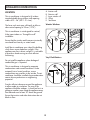
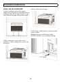
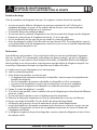
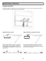
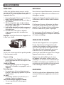
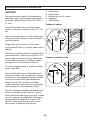
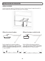
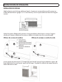
LOCATION
This air conditioner is designed to fi t inside a
standard double-hung window width opening
widths of 22 - 36” (55.9 - 91.4 cm).
The lower sash must open suffi ciently to allow a
clear vertical opening of 35 cm (13.75”).
This air conditioner is not designed for vertical,
slider type windows or “through the wall”
installation.
Ensure that the window and frame are structurally
sound and free from dry or rotted wood.
Install the air conditioner on a side of the building
which favors more shade than sunlight. If the
appliance must be in direct sunlight, it is advisable
to provide a shade awning to ensure effi cient
functioning.
Do not install the appliance where leakage of
combustible gas is suspected.
This air conditioner is designed to evaporate
condensation under normal conditions. Under
extremely hot or humid conditions, excess
condensation may overfl ow to the outside. The air
conditioner should be installed where condensation
cannot drip on pedestrians or neighboring
properties.
Provide suffi cient clearance around the appliance
to allow ample air circulation. The rear of the
appliance should be outdoors, it should not be in a
garage or another room. Keep the appliance away
from obstacles and at least 30” above the ground.
Ensure that curtains and other obstructions do not
block air fl ow.
13.75" min
22" to 36"
(55.9 cm to 91.4 cm)
(35 cm)
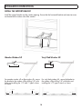
A
B
C
D
E
A. Interior wall
B. Exterior wall
C. Inner window sill
D. Offset
E. Seal foam
Wooden Windows
Vinyl-Clad Windows
13.75" min
22" to 36"
(55.9 cm to 91.4 cm)
(35 cm)
A
B
C
D
E

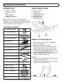
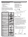
* Denotes extra hardware provided in separate bag.
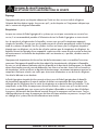
INSTALLATION INSTRUCTIONS
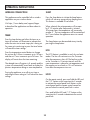
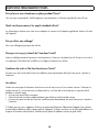
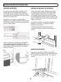
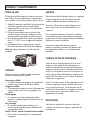
SUPPORT BRACKET DETAILS
1. Rear cross brace
2. Main support
3. Left extension arm
4. Angled support arms
5. Horizontal bracket
6. Spring push pin
7. Right extension arm
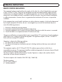
REQUIRED TOOLS
• Phillips screwdriver
• Flat head screwdriver
• Pencil
• Measuring Tape
• Carpenter’s Level
• Drill and 1/8” drill bit
Note: Save the shipping carton and packing
materials for future storage or transportation. Please
check the contents of the accessory bags against the
below check list prior to installation.
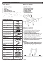
INCLUDED ACCESSORIES
1/2” type B screw (x2) *
1/4” type B screw (x2) *
1” type A screw (x2) *
1/2” type A screw (x3) *
Support bracket
Right extension arm
Right extension arm (short)
Main support pin (x2) *
Cotter pin (x2) *
Right open window bracket
Left open window bracket
Side arm foam (x2)
Window sash lock
Window sash foam
Window sealing foam
Bracket sealing foam
Additional side arm foam
1
2
3
4
5
6
7
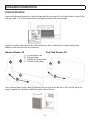
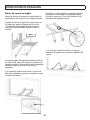
PREPARE THE SUPPORT BRACKET
1. Find the center of the window sill and lightly
mark it with a pencil.
2. Measure the width of the window.
3. Adjust the left extension arm, then install and
adjust the right extension arm to the correct
width by pressing the spring push pins. Note
that the bracket may be slightly offset to the left
of center when placed in the window.
4. Apply the bracket sealing foam to the bottom of
the left and right extension arms.
Important:
• Windows with widths between 26 - 36” should
use the right extension arm.
• Windows with widths between 26 - 26” should
used the short right extension arm

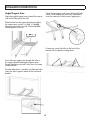
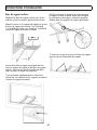
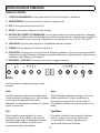
INSTALL THE SUPPORT BRACKET
Install the support bracket into the window opening. Ensure that the horizontal bracket and extension arms
are located on the indoor side of the window.
INSTALLATION INSTRUCTIONS
14
Wooden Window Sill Vinyl-Clad Window Sill
For wooden window sills or fl at window sills, secure
the bracket to the window sill by drilling 1/8” pilot
holes and installing the 1/2” and 1” type A screws
as shown.
For vinyl-clad window sills, secure the bracket to
the window sill by drilling 1/8” pilot holes and
installing the 1/2” type A screws as shown.
1” Type A
1” Type A
1/2” Typ e A 1/2” Type A
1/2” Type A
1/2” Type A

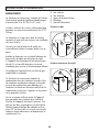
INSTALLATION INSTRUCTIONS
Angled Support Arms
Move the angled support arms toward the exterior
wall until the feet touch the wall.
Place the level on the support bracket and adjust
the support arms so that it is tilted 1/4 bubble
downward toward the outside. The level bubble
should appear as shown.
15
Insert the main support pin through the holes in
the support bracket and angled support arms.
Ensure that the pins on both sides are in the same
numbered hole.
If further adjustment is needed, use alternate holes
where the main supports attach to the horizontal
bracket.
Check the level again and ensure the bracket feels
secure. After making any necessary adjustments,
insert the cotter pins into the main support pins.
If necessary, cover the holes in the front of the
bracket with the bracket sealing foam.

16
INSTALLATION INSTRUCTIONS
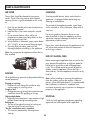
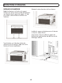
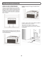
INSTALL THE AIR CONDITIONER
Set the air conditioner on top of the support
bracket. Ensure the grooves on the bottom of the air
conditioner align with the support bracket. Using a
level, check for the proper tilt toward the outside.
Pull the window down into the slot in the air
conditioner to hold it steady but do not close it all
the way yet.
Fold down both side arm hinges.
Install the open window brackets using the provided
screws as shown.
Warning: Failing to install the open window
brackets could cause injury or property damage.
1/2” type B
1/4” type B

INSTALLATION INSTRUCTIONS
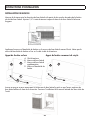
FOAM INSTALLATION
Measure the distance between the side arm hinge and the closest part of the window frame in side with the
side arm. Add 1/4” to this distance and cut the side arm foam to the correct length.
Wooden Window Sill Vinyl-Clad Window Sill
Apply the window sealing foam to the side arm foam as shown. Note that the window sealing foam
attaches to the side next to the air conditioner.
A
B
C
D
A
B
D
17
Insert side arm foam into the side arm hinge until the top front of the side arm is fl ush with the top of the
hinge. Complete the side foam installation on both sides of the unit.
A. Air conditioner side
B. Side arm foam
C. Additional side arm foam
D. Window sealing foam

INSTALLATION INSTRUCTIONS
18
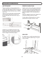
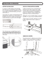
ANTI TIP BRACKET
The anti tip brackets must be extended into the
window track opening until. Remove the screw from
the anti tip bracket, extend it as far as it will go to
the side of the window and then secure it with the
same screw.
Warning: The anti tip brackets must be extended
into the window track opening. Failure to use
the anti tip brackets can cause serious injury or
damage.
See below for an example of what the anti tip
bracket should look like when properly installed.
Note that the side arm foam has been removed
from this images for illustration purposes.
WINDOW SEALING FOAM
Install a strip of window sealing foam to the bottom
of the lower sash to seal any small gaps between
the window and the air conditioner. Make sure the
window is completely closed and then check for
gaps. Fill any gaps with the remaining foam as
needed.
Extend the integrated window locks, located in the
U-channel, until they contact the window.
Cut the window sash foam and insert it into the
space between the upper and lower sashes.
SASH LOCK
For added security, install the optional sash lock.
Secure the sash lock in place using 1/2” type A
screws as shown.

OPERATING INSTRUCTIONS
3s
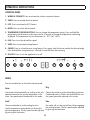
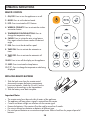
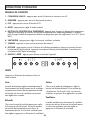
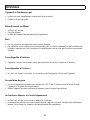
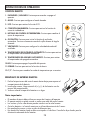
CONTROL PANEL
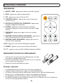
1. WIRELESS CONNECT: Press to activate the wireless connection feature.
2. TIMER: Press to activate the timer feature.
3. ECO: Press to activate the ECO feature.
4. MODE: Press to set the desired mode.
5. TEMPERATURE CONTROL BUTTONS: Press to change the temperature setting. Press and hold the
temperature control buttons at the same time for 3 seconds to change the temperature scale being
displayed. The temperature can be set between 16 - 30°C (60 - 86°F).
6. FAN: Press to set the desired fan speed.
7. SLEEP: Press to activate the sleep feature.
8. SWING: Press to initiate the auto swing feature. Press again when the louver reaches the desired angle.
Press and hold the swing button for 3 seconds to reset the fi lter after cleaning.
9. ON/OFF: Press to turn the appliance on or off.
19
MODE
Press the mode button to choose the desired mode.
Auto
Auto mode will automatically set cooling or fan only
operation based on the current temperature in the
room. Fan speed cannot be adjusted in this mode.
Cool
Choose cool mode to set the cooling function.
Use the temperature control buttons to choose the
desired temperature. The fan speed can be adjusted
by pressing the fan button.
Dry
Choose dry mode to set the dehumidifying function.
Condensed water will drain out the back of the unit.
Fan speed cannot be adjusted in this mode.
Fan
Fan mode will run the internal fan without engaging
the cooling function. The fan speed can be adjusted
by pressing the fan button.
La page charge ...
La page charge ...
La page charge ...
La page charge ...
La page charge ...
La page charge ...
La page charge ...
La page charge ...
La page charge ...
La page charge ...
La page charge ...
La page charge ...
La page charge ...
La page charge ...
La page charge ...
La page charge ...
La page charge ...
La page charge ...
La page charge ...
La page charge ...
La page charge ...
La page charge ...
La page charge ...
La page charge ...
La page charge ...
La page charge ...
La page charge ...
La page charge ...
La page charge ...
La page charge ...
La page charge ...
La page charge ...
La page charge ...
La page charge ...
La page charge ...
La page charge ...
La page charge ...
La page charge ...
La page charge ...
La page charge ...
La page charge ...
La page charge ...
La page charge ...
La page charge ...
La page charge ...
La page charge ...
La page charge ...
La page charge ...
La page charge ...
La page charge ...
La page charge ...
La page charge ...
La page charge ...
La page charge ...
La page charge ...
La page charge ...
La page charge ...
La page charge ...
La page charge ...
La page charge ...
-
 1
1
-
 2
2
-
 3
3
-
 4
4
-
 5
5
-
 6
6
-
 7
7
-
 8
8
-
 9
9
-
 10
10
-
 11
11
-
 12
12
-
 13
13
-
 14
14
-
 15
15
-
 16
16
-
 17
17
-
 18
18
-
 19
19
-
 20
20
-
 21
21
-
 22
22
-
 23
23
-
 24
24
-
 25
25
-
 26
26
-
 27
27
-
 28
28
-
 29
29
-
 30
30
-
 31
31
-
 32
32
-
 33
33
-
 34
34
-
 35
35
-
 36
36
-
 37
37
-
 38
38
-
 39
39
-
 40
40
-
 41
41
-
 42
42
-
 43
43
-
 44
44
-
 45
45
-
 46
46
-
 47
47
-
 48
48
-
 49
49
-
 50
50
-
 51
51
-
 52
52
-
 53
53
-
 54
54
-
 55
55
-
 56
56
-
 57
57
-
 58
58
-
 59
59
-
 60
60
-
 61
61
-
 62
62
-
 63
63
-
 64
64
-
 65
65
-
 66
66
-
 67
67
-
 68
68
-
 69
69
-
 70
70
-
 71
71
-
 72
72
-
 73
73
-
 74
74
-
 75
75
-
 76
76
-
 77
77
-
 78
78
-
 79
79
-
 80
80


Danby DAC100B6IWDB-6 Le manuel du propriétaire
- Taper
- Le manuel du propriétaire
- Ce manuel convient également à
dans d''autres langues
Documents connexes
-
Danby DPA100B9IWDB-6 Le manuel du propriétaire
-
Danby DPA086B8BDB-6 Le manuel du propriétaire
-
Danby DAC050MB1WDB Le manuel du propriétaire
-
Danby DPA065B6WDB-6 Le manuel du propriétaire
-
Danby DPA060B1WDB Le manuel du propriétaire
-
Danby DAC080B5WDB Le manuel du propriétaire
-
-
Yes DAC100B5WDB Le manuel du propriétaire
-
-
Danby DAC050ME1WDB Le manuel du propriétaire
Autres documents
-
mundoclima Series MUPO-C9/H9 Guide d'installation
-
Panasonic CU2TZ50TBE Mode d'emploi
-
Panasonic CSZ50XKEW Mode d'emploi
-
Panasonic CSXZ35VKEW Le manuel du propriétaire
-
Panasonic CSPZ35VKE Mode d'emploi
-
RCA RACE8024-6COM Electronic Window Air icon Conditioner Manuel utilisateur
-
TCL TWC-08CR/UH Guide d'installation
-
Samsung AW05N0YAH Manuel utilisateur
-
TCL 5K-14K Mode d'emploi
-