KitchenAid KUIS18NNTS3 Le manuel du propriétaire
- Taper
- Le manuel du propriétaire

I_itchen_kid ®
ICE MAKER
For questions about features, operation/performance, parts, accessories or service, call: 1-800-422-1230 or visit our website at...
www.kitchenaid.com
In Canada, for assistance, installation and service, call: 1-800-807-6777 or visit our website at...
www.KitchenAid.ca
MACHINE A GLA(_ONS
Au Canada, pour assistance, installation ou service composez le 1-800-807-6777 ou visitez notre site Web &...
www.KitchenAid.ca
Table of Contents/Table des matieres ............................................................................. 2
W10206425A

TABLEOF CONTENTS
ICE MAKER SAFETY ...................................................................... 3
INSTALLATION INSTRUCTIONS .................................................. 4
Unpack the Ice Maker .................................................................. 4
Location Requirements ................................................................ 4
Electrical Requirements ............................................................... 5
Water Supply Requirements ........................................................ 5
Leveling ........................................................................................ 5
Connect Water Supply ................................................................. 6
Drain Connection ......................................................................... 7
Normal Sounds ............................................................................ 8
ICE MAKER USE ............................................................................ 8
How Your Ice Maker Works ......................................................... 8
Using the Controls ....................................................................... 9
ICE MAKER CARE .......................................................................... 9
Cleaning ........................................................................................ 9
Vacation and Moving Care ......................................................... 11
TROUBLESHOOTING .................................................................. 12
Ice Maker Operation ................................................................... 12
Ice Production ............................................................................ 12
Ice Quality ................................................................................... 13
Plumbing Problems .................................................................... 13
ASSISTANCE OR SERVICE ......................................................... 14
In the U.S.A ................................................................................ 14
In Canada ................................................................................... 14
WAR RANTY .................................................................................. 15
TABLEDES MATIERES
SI_CURITI_ DE LA MACHINE ,&,GLA(_,ONS................................ 17
INSTRUCTIONS D'INSTALLATION ............................................ 18
Deballage de la machine a gla_ons ........................................... 18
Emplacement d'installation ........................................................ 18
Specifications electriques .......................................................... 19
Specifications de I'alimentation en eau ..................................... 19
Nivellement ................................................................................. 19
Raccordement &la canalisation d'eau ...................................... 20
Raccordement au conduit d'evacuation ................................... 21
Sons normaux ............................................................................ 22
UTILISATION DE LA MACHINE ,&,GLA_ONS ............................ 23
Fonctionnement de la machine &gla_ons ................................. 23
Utilisation des commandes ........................................................ 23
ENTRETIEN DE LA MACHINE ,&GLA(_,ONS.............................. 24
Nettoyage ................................................................................... 24
Precautions & prendre pour les vacances
ou le dem6nagement .................................................................. 26
DI_PAN NAG E................................................................................. 27
Fonctionnement de la machine &gla(_ons................................. 27
Production de gla£_ons............................................................... 28
Qualite des gla£;ons.................................................................... 28
Problemes de plomberie ............................................................ 28
ASSISTANCE OU SERVICE ......................................................... 29
GARANTIE ..................................................................................... 30
2

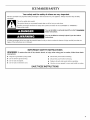
ICE MAKER SAFETY
Your safety and the safety of others are very important.
We have provided many important safety messages in this manual and on your appliance. Always read and obey all safety
messages.
This is the safety alert symbol.
This symbol alerts you to potential hazards that can kill or hurt you and others.
All safety messages will follow the safety alert symbol and either the word "DANGER" or "WARNING."
These words mean:
You can be killed or seriously injured if you don't immediately
follow instructions.
You can be killed or seriously injured if you don't follow
instructions.
All safety messages will tell you what the potential hazard is, tell you how to reduce the chance of injury, and tell you what can
happen if the instructions are not followed.
IMPORTANT SAFETY INSTRUCTIONS
WARNING: To reduce the risk of fire, electric shock, or injury when using your ice maker, follow these basic
precautions:
• Plug into a grounded 3 prong outlet.
• Do not remove ground prong.
• Do not use an adapter.
• Do not use an extension cord.
• Disconnect power before cleaning.
• Disconnect power before servicing.
• Replace all parts and panels before operating.
• Use two or more people to move and install ice maker.
SAVE THESE INSTRUCTIONS

INSTALLATION INSTRUCTIONS
Excessive Weight Hazard
Use two or more people to move and installicemaker.
Failureto do so can resultinback or other injury.
Removing Packaging Materials
Remove tape and glue from your ice maker before using.
• To remove any remaining tape or glue from the exterior of the
ice maker, rub the area briskly with your thumb. Tape or glue
residue can also be easily removed by rubbing a small
amount of liquid dish soap over the adhesive with your
fingers. Wipe with warm water and dry.
• Do not use sharp instruments, rubbing alcohol, flammable
fluids, or abrasive cleaners to remove tape or glue. Do not
use chlorine bleach on the stainless steel surfaces of the ice
maker. These products can damage the surface of your ice
maker.
Cleaning Before Use
After you remove all of the packaging materials, clean the inside
of your ice maker before using it. See the cleaning instructions in
the "Ice Maker Care" section.
• To ensure proper ventilation for your ice maker, the front side
must be completely unobstructed. The ice maker may be
closed-in on the top and three sides, but the installation
should allow the ice maker to be pulled forward for servicing
if necessary.
• Installation of the ice maker requires a cold water supply inlet
of V4"(6.35 mm) OD soft copper tubing with a shutoff valve
and either a gravity-drain system or condensate pump to
carry the water to an existing drain.
• Choose a well ventilated area with temperatures above 55°F
(13°C) and below 100°F (38°C). Best results are obtained
between 70°F (21°C) and 90°F (32°C).
• This ice maker must be installed in an area sheltered from the
elements, such as wind, rain, water spray or drips.
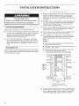
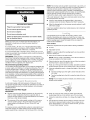
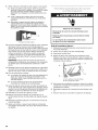
• When installing the ice maker under a counter, follow the
recommended opening dimensions shown. Place electrical
and plumbing fixtures in the recommended location as
shown.
NOTES:
• Be sure the power supply cord is not pinched between
the ice maker and the cabinet.
• Be sure the water supply line is not pinched between the
ice maker and the cabinet.
• Be sure the drain line (on some models) is not pinched
between the ice maker and the cabinet.
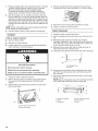
34"
(86.4 cm)
Min.
341/2"
(87.6 cm)
Max.
281/2"
(72.4 cm)
B
cm)
(45.7 cm)
A.Recommended location for
electrical and plumbing fixtures
B.Floor level
Choose a location where the floor is even. It is important for
the ice maker to be level in order to work properly. If needed,
you can adjust the height of the ice maker by changing the
height of the leveling legs. See the "Leveling" section.

Electrical Shock Hazard
Plug into a grounded 3 prong outlet.
Do not remove ground prong.
Do not use an adapter.
Do not use an extension cord.
Failure to follow these instructions can result in death,
fire, or electrical shock.
Before you move your ice maker into its final location, it is
important to make sure you have the proper electrical
connection:
A 115 Volt, 60 Hz., AC only, 15- or 20-amp electrical supply,
properly grounded in accordance with the National Electrical
Code and local codes and ordinances, is required.
It is recommended that a separate circuit, serving only your ice
maker, be provided. Use a receptacle which cannot be turned off
by a switch or pull chain.
IMPORTANT: If this product is connected to a GFCI (Ground
Fault Circuit Interrupter) equipped outlet, nuisance tripping of the
power supply may occur, resulting in loss of cooling. Ice quality
may be affected. If nuisance tripping has occurred, and if the
condition of the ice appears poor, dispose of it.
Recommended grounding method
The ice maker must be grounded. The ice maker is equipped with
a power supply cord having a 3 prong grounding plug. The cord
must be plugged into a mating, 3 prong, grounding-type wall
receptacle, grounded in accordance with the National Electrical
Code and local codes and ordinances. Ifa mating wall receptacle
is not available, it is the personal responsibility of the customer to
have a properly grounded, 3 prong wall receptacle installed by a
qualified electrician.
A cold water supply with water pressure of between 30 and
120 psi (207 and 827 kPa) is required to operate the ice maker. If
you have questions about your water pressure, call a licensed,
qualified plumber.
Reverse Osmosis Water Supply
IM PORTANT:
• Reverse osmosis water filtration systems can be used only
with ice maker installations that have a gravity drain. A
reverse osmosis system is not recommended for ice makers
that have a drain pump installed.
• The pressure of the water supply coming out of a reverse
osmosis system going to the water inlet valve of the ice
maker needs to be between 30 and 120 psi (207 and
827 kPa).
If a reverse osmosis water filtration system is connected to your
cold water supply, the water pressure to the reverse osmosis
system needs to be a minimum of 40 to 60 psi (276 to 414 kPa).
NOTE: The reverse osmosis system must provide 1 gal. (3.8 L) of
water per hour to the ice maker for proper ice maker operation. If
a reverse osmosis system is desired, only a whole-house
capacity reverse osmosis system, capable of maintaining the
steady water supply required by the ice maker, is recommended.
Faucet capacity reverse osmosis systems are not able to
maintain the steady water supply required by the ice maker.
If the water pressure to the reverse osmosis system is less than
40 to 60 psi (276 to 414 kPa):
• Check to see whether the sediment filter in the reverse
osmosis system is blocked. Replace the filter if necessary.
• Allow the storage tank on the reverse osmosis system to refill
after heavy usage.
If you have questions about your water pressure, call a licensed,
qualified plumber.
It is important for the ice maker to be level in order to work
properly. Depending upon where you install the ice maker, you
may need to make several adjustments to level it. You may also
use the leveling legs to lower the height of the ice maker for
undercounter installations.
Tools needed:
Gather the required tools and parts before starting installation.
• 9" level
• Adjustable wrench
NOTE: It is easier to adjust the leveling legs if you have another
person to assist you.
1. Move the ice maker to its final location.
NOTE: If this is a built-in installation, move the ice maker as
close as possible to the final location.
2. Place the level on top of the product to see if the ice maker is
level from front to back and side to side.
3. Push up on the top front of the ice maker, and then locate the
leveling screws that are on the bottom front of the ice maker.
4. Using an adjustable wrench, change the height of the legs as
follows:
• Turn the leveling leg to the right to lower that side of the
ice maker.
• Turn the leveling leg to the left to raise that side of the ice
maker.
NOTE: The ice maker should not wobble. Use shims to add
stability when needed.
5. Push up on the top rear of the ice maker and locate the
leveling legs that are on the bottom rear of the ice maker.
6. Follow the instructions in Step 4 to change the height of the
legs.
7. Use the level to recheck the ice maker to see that it is even
from front to back and side to side. If the ice maker is not
level, repeat steps 2 to 5. If the ice maker is level, go to the
"Connect Water Supply" section.

Readalldirectionsbeforeyoubegin.
IMPORTANT:
Plumbingshallbeinstalledinaccordancewiththe
InternationalPlumbingCodeandanylocalcodesand
ordinances.
• UsecoppertubingorWhirlpoolsupplyline,PartNumber
8212547RP,andcheckforleaks.
• Installtubingonlyinareaswheretemperatureswillremain
abovefreezing.
Toolsneeded:
Gathertherequiredtoolsandpartsbeforestartinginstallation.
• Flat-bladescrewdriver
• 7Ae"andV2"open-end wrenches or two adjustable wrenches
• V4"nut driver
NOTE: Do not use a piercing-type or 3Ae"(4.76 mm) saddle valve
which reduces water flow and clogs more easily.
Connecting the Water Line
4,
Y
£
Place the free end of the tubing into a container or sink, and
turn on main water supply and flush out tubing until water is
clear. Turn off shutoff valve on the water pipe.
NOTE: Always drain the water line before making the final
connection to the inlet of the water valve to avoid possible
water valve malfunction.
1,
2.
Turn off main water supply. Turn on nearest faucet long
enough to clear line of water.
Using a V2"copper supply line with a quarter-turn shutoff
valve or the equivalent, connect the ice maker as shown.
NOTE: To allow sufficient water flow to the ice maker a
minimum V2"size copper supply line is recommended.
A
I/ II
B
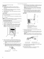
5. Bend the copper tubing to meet the water line inlet which is
located on the back of the ice maker cabinet as shown.
Leave a coil of copper tubing to allow the ice maker to be
pulled out of the cabinet or away from the wall for service.
REAR VIEW
B
C
D
6,
7.
A. Water supply tube clamp
B. Vent hose (drain pump models only)
C. Inlet water tube clamp and supply
line connector
D. Drain hose (drain pump models only)
Remove and discard the short, black plastic tube from the
end of the water line inlet.
Thread the nut onto the end of the tubing. Tighten the nut by
hand. Then tighten it with a wrench two more turns. Do not
overtighten.
NOTE: To avoid rattling, be sure the copper tubing does not
touch the cabinet's side wall or other parts inside the cabinet.
3,
A. Bulb
B. Nut
Now you are ready to connect the copper tubing. Use V4"
(6.35 mm) OD soft copper tubing for the cold water supply.
• Ensure that you have the proper length needed for the
job. Be sure both ends of the copper tubing are cut
square.
Slip compression sleeve and compression nut on copper
tubing as shown. Insert end of tubing into outlet end
squarely as far as it will go. Screw compression nut onto
outlet end with adjustable wrench. Do not overtighten.
A. Compression sleeve
B. Compression nut
C. Copper tubing
A B C D
A. Line to ice maker
B. Nut (purchased)
C. Ferrule (purchased)
D. Suppfied fine from ice maker
8. Install the water supply tube clamp around the water supply
line to reduce strain on the coupling.
9. Turn shutoff valve ON.
10. Check for leaks. Tighten any connections (including
connections at the valve) or nuts that leak.
6

I_-i!_}_IiI?<. () ] ?eCll)l]
Gravity Drain System
Connect the ice maker drain to your drain in accordance with all
state and local codes and ordinances. Ifthe ice maker is
provided with a gravity drain system, follow these guidelines
when installing drain lines. This will help keep water from flowing
back into the ice maker storage bin and potentially flowing onto
the floor causing water damage.
• Drain lines must have a minimum of 5/8"(15.88 mm) inside
diameter.
• Drain lines must have a 1" drop per 48" (2.54 cm drop per
122 cm) of run or 1/4"drop per 12" (6.35 mm per 30.48 cm) of
run and must not have low points where water can settle.
• The floor drains must be large enough to accommodate
drainage from all drains.
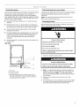
• The ideal installation has a standpipe with a 1W' (3.81 cm) to
2" (5.08 cm) PVC drain reducer installed directly below the
outlet of the drain tube as shown. You must maintain a
1" (2.54 cm) air gap between the drain hose and the
standpipe.
• It may be desirable to insulate the drain line thoroughly up to
the drain inlet.
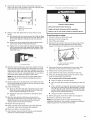
SIDE VIEW
I
I
17/8 ''
(1.9 cm)
20" (50.80 cm)
(5 cm - 3.8 cm)
C
D
A. Drain hose
B. 1" (2.54 cm) air gap
C. PVC drain reducer
D. Center of drain should be 20" (50.80 cm) from front of
door, with or without the 3/4"(1.91 cm) panel on the door.
The drain should also be centered from left to right (81_,,
from either side of the ice maker).
Drain Pump System (on some models)
Connect the ice maker drain to your drain in accordance with the
International Plumbing Code and any local codes and
ordinances.
NOTE: If the drain hose becomes twisted and water cannot
drain, your ice maker will not work.
Connecting the Drain
After ensuring that the drain system is adequate, follow these
steps to properly place the ice maker:
Electrical Shock Hazard
Plug into a grounded 3 prong outlet.
Do not remove ground prong.
Do not use an adapter.
Do not use an extension cord.
Falure to folow these instructions can result in death,
fire, or electrical shock.
1. Plug into a grounded 3 prong outlet.
Excessive Weight Hazard
Use two or more people to move and install ice maker.
Failure to do so can result in back or other injury.
2. Style 1 - For gravity drain system, push the ice maker into
position so that the ice maker drain tube is positioned over
the PVC drain reducer. Style 2 - For drain pump system
connect the drain pump outlet hose to the drain. See "Drain
Pump System."
3. Recheck the ice maker to be sure that it is level. See
"Leveling."
4. If it is required by your local sanitation code, seal the cabinet
to the floor with an approved caulking compound after all
water and electrical connections have been made.

_.x@ttltal SOUI_5
Yournewicemakermaymakesoundsthatarenotfamiliarto
you.Becausethesoundsarenewtoyou,youmightbe
concernedaboutthem.Mostofthenewsoundsarenormal.Hard
surfacessuchasfloors,wallsandcabinetscanmakethesounds
seemlouderthantheyactuallyare.Thefollowingdescribesthe
kindsofsoundsthatmightbenewtoyouandwhatmaybe
makingthem.
• Youwillhearabuzzingsoundwhenthewatervalveopensto
fillthewaterreservoirforeachcycle.
• Rattlingnoisesmaycomefromtheflowoftherefrigerantor
thewaterline.Itemsstoredontopoftheicemakercanalso
makenoises.
• Thehigh-efficiencycompressormaymakeapulsatingorhigh
pitchedsound.
• Waterrunningovertheevaporatorplatemaymakea
splashingsound.
• Waterrunningfromtheevaporatorplatetothewaterreservoir
maymakeasplashingsound.
• Aseachcycleends,youmayhearagurglingsounddueto
therefrigerantflowinginyouricemaker.
• Youmayhearairbeingforcedoverthecondenserbythe
condenserfan.
• Duringtheharvestcycle,youmayheara"thud"whentheice
sheetslidesfromtheevaporatorontothecuttergrid.
• Whenyoufirststarttheicemaker,youmayhearwater
runningcontinuously.Theicemakerisprogrammedtoruna
rinsecyclebeforeitbeginstomakeice.
ICE MAKER USE
The Ice Making Process
1. Water is constantly circulated over a freezing plate. As the
water freezes into ice, the minerals in the water are rejected.
This produces a sheet of ice with a low mineral content.
2.
When the desired thickness is reached, the ice sheet is
released and slides onto a cutter grid. The grid divides the
sheet into individual cubes.
3. The water containing the rejected minerals is drained after
each freezing cycle.
4. Fresh water enters the machine for the next ice making cycle.
5. Cubes fall into the storage bin. When the bin is full, the ice
maker shuts off automatically and restarts when more ice is
needed. The ice bin is not refrigerated, and some melting will
occur. The amount of melting varies with room temperature.
%0;11 ICe
When you first start your ice maker, the water pan will fill and the
system will rinse itself before starting to make ice. The rinsing
process takes about 5 minutes.
Under normal operating conditions, the ice maker will cycle at
preset temperatures. The ice level sensor located in the ice
storage bin will monitor the ice levels.
IMPORTANT:
• If the water supply to the ice maker is turned off, be sure to
set the ice maker control to OFR
• The ice maker is designed to make clear ice from the majority
of water sources on a daily basis. If your results are
unsatisfactory, your water may need to be filtered or treated.
NOTE: As the room and water temperatures vary, so will the
amount of ice produced and stored. This means that higher
operating temperatures result in reduced ice production.
8

I. To starticeproduction,pressON.
2. To stop icemaker operation,pressOFF.
Holiday Clean /
On / Off Mode Service Reset
0000
NOTES:
• Pressing the On/Off switch does not shut off power to the ice
maker.
• Allow 24 hours to produce the first batch of ice. Discard the
first batch produced.
Holiday Mode
The Holiday Mode feature is designed for those whose religious
observances require turning off the lights and the ice maker. By
selecting this feature, ice production will be disabled and the
interior lights will turn off.
Press and hold the HOLIDAY MODE button to turn on the Holiday
Mode feature. Press and hold the button again to turn off the
feature.
Service
The service light indicates when service is needed. If the service
light turns on, turn the ice maker off and back on. If the service
light turns on again, call for service.
Clean/Reset
The Cleaning/Reset Status light will help you know when it is time
to clean your ice maker. The light will change from green to
yellow. This tells you it is almost time to clean your ice maker. It is
recommended that you clean the ice maker when the status light
changes to red OR ice production decreases significantly. To
clean your ice maker, see "Ice Maker System" in the "Cleaning"
section.
ICE MAKER CARE
The ice making system and the air cooled condenser need to be
cleaned regularly for the ice maker to operate at peak efficiency
and to avoid premature failure of system components. See the
"Ice Maker System" and the "Condenser" sections.
Exterior Surfaces
Wash the exterior enamel surfaces and gaskets with warm water
and mild soap or detergent. Wipe and dry. Regular use of a good
household appliance cleaner and wax will help maintain the
finish. Do not use abrasive cleaners on enamel surfaces as they
may scratch the finish.
For products with a stainless steel exterior, use a clean sponge or
soft cloth and a mild detergent in warm water. Do not use
abrasive or harsh cleaners. Do not use chlorine bleach on the
stainless steel surfaces.
Ice Maker System
Minerals that are removed from water during the freezing cycle
will eventually form a hard scaly deposit in the water system.
Cleaning the system regularly helps remove the mineral scale
buildup. How often you need to clean the system depends upon
how hard your water is. With hard water of 15 to 20 grains/gal.
(4 to 5 grains/liter), you may need to clean the system as often as
every 6 months.
NOTE: Use one 16 oz (473 mL) bottle of approved ice maker
cleaner. To order, call 1-800-442-9991 and ask for Part Number
4396808. In Canada, call 1-800-807-6777.
1. Press selector switch to OFR
2. Wait 5 to 10 minutes for the ice to fall into the storage bin.
Remove all ice from the storage bin.
3. Unscrew the drain cap from the bottom of the water pan
located inside the storage bin as shown. Allow the water to
drain completely.
4. Replace the drain cap securely on the water pan. If the drain
cap is loose, water will empty from the water pan and you will
have either thin ice or no ice.
5. Read and follow all handling information on the cleaner bottle
before completing the steps below. Use one 16 oz (473 mL)
bottle of approved ice maker cleaner.
6. Pour one bottle of solution into the water pan. Fill the bottle
twice with tap water and pour it into the water pan.
g ...........
t ........I \\ [o \ - j '
_ ........._ ..............A
..................B
,, C
A. Water pan
B. Water pan thumb screws
C. Drain cap

7. Press the CLEAN button. See "Using the Controls." The light
will blink, indicating that the cleaning cycle is in process.
When the indicator light turns green (approximately
70 minutes), the cleaning cycle is complete. During the
cleaning cycle, the system will both clean and rinse itself.
8. After the cleaning cycle is complete, remove the drain cap
from the water pan. Look for any cleaning solution left in the
water pan. If cleaning solution drains from the water pan, you
should run the clean cycle again. Be sure to replace the drain
cap securely on the water pan. If the drain cap is loose, water
will empty from the water pan and you will have either thin ice
or no ice.
NOTE: Severe scale buildup may require repeated cleaning with
a fresh quantity of cleaning solution.
9. Push the selector switch to ON to resume ice production.
Condenser
A dirty or clogged condenser:
• Obstructs proper airflow.
• Reduces ice making capacity.
• Causes higher than recommended operating temperatures
which may lead to component failure.
Electrical Shock Hazard
Disconnect power before cleaning.
Replace all parts and panels before operating.
Failure to do so can result in death or electrical shock.
1. Unplug ice maker or disconnect power.
2. Remove the two screws in the lower access panel and the
two screws from the base grille area of the front panel
support.
3. Pull the bottom forward and then pull down to remove the
lower access panel.
..............................A
A. Lower access panel screws
B. Base grifle screws
4= Remove dirt and lint from the condenser fins and the unit
compartment with a brush attachment on a vacuum cleaner.
5. Replace the lower access panel using the four screws.
6. Plug in ice maker or reconnect power.
Interior Components
1. Unplug ice maker or disconnect power.
2. Open the storage bin door and remove any ice that is in the
bin.
3. Remove the drain cap from the water pan and drain
thoroughly. Replace the drain cap securely on the water pan.
If the drain cap is loose, water will empty from the water pan,
and you will have either thin ice or no ice.
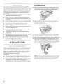
4. Remove the two screws that hold the cutter grid cover in
place and remove the cutter grid cover.
5. Unplug the wiring harness from the left side of the cutter grid.
A. Cutter grid cover
B. Screws
6. Unplug the ice level sensor from the right side of the cutter
grid. Pull the ice level sensor down and forward away from
the cutter grid.
7. Remove the right-hand and left-hand screws. Lift the cutter
grid up and out.
NOTE: Make sure the plastic spacer from the right-hand side
of the cutter grid bracket stays with the cutter grid.
A. Cutter grid harness
B. Screw
C. Cutter grid
D. Ice level sensor harness
E. Plastic spacer
F. Screw
10

8.
9.
Remove the two thumb screws that hold the water pan in
place. Push down with one hand on the front of the pan while
pulling forward on the bottom back side.
B--
_ ................A
...................B
A. Water pan
B. Water pan thumb screws
C. Drain cap
Remove, clean and replace the ice scoop and ice scoop
holder.
After removing the ice scoop, remove the holder by lifting
the front free from the cutter grid cover. Then lift the back
of the holder slightly to release the rear hook and pull
forward.
Wash the ice scoop holder along with the other interior
components using the following instructions.
Replace the ice scoop holder by aligning the rear hook
with the opening (the holder angles down slightly). Slide
the holder back fully until the front rests securely on the
cutter grid cover.
A
A. Ice scoop holder
10. Wash the interior components (cutter grid, exterior of hoses,
and water pan) and the storage bin, door gasket, ice scoop,
and ice scoop holder with mild soap or detergent and warm
water. Rinse in clean water. Then clean the same parts with a
solution of 1 tbs (15 mL) of household bleach in 1 gal. (3.8 L)
warm water. Rinse again thoroughly in clean water.
NOTE: Do not remove hoses. Do not wash plastic parts in
dishwasher. They cannot withstand temperatures above
145°F (63°C).
11. Replace water pan by pushing back on the bottom with one
hand while pushing up and back on the top. Secure the water
pan by replacing both screws.
12. Check the following:
• Drain cap from the water pan is securely in place. If the
drain cap is loose, water will empty from the water pan,
and you will have either thin ice or no ice.
• Hose from water pan is inserted into storage bin drain
opening.
13. Slide the cutter grid back into place and secure it by
replacing the right-hand screw and plastic spacer. Then
tighten the left-hand screw. Reconnect the cutter grid
harness and the ice level sensor harness.
14. Replace the cutter grid cover.
15. Gently wipe the control panel with a soft, clean dishcloth
using warm water and a mild liquid dish detergent.
16. Plug in ice maker or reconnect power.
17. After cleaning, make sure that all controls are set properly
and that no control indicators are flashing.
Vacal:l<)l] al]d ...... '" ..... ' I)WIIII { II'I _
Electrical Shock Hazard
Disconnect power before servicing.
Replace all parts and panels before operating.
Failure to do so can result in death or electrical shock.
To shut down the ice maker:
1. Unplug ice maker or disconnect power.
2. Remove all ice from storage bin.
3. Shut off the water supply.
4. Remove the two screws in the lower access panel and the
two screws from the base grille area of the front panel
support. Pull forward to remove the lower access panel.
i _1 .............................A
............... B
A.Lower access panel screws
B.Base grille screws
5. Disconnect the inlet and outlet lines to water valve. Allow
these lines to drain and then reconnect to the valve.
6. Replace lower access panel and screws.
7. Drain water from water pan by removing the drain cap.
8. If the room temperature will drop below 32°F (0°C), water
must be removed from the drain line.
For ice makers with a drain pump installed:
• Plug in ice maker or reconnect power.
• Turn ice maker off and remove all remaining ice from ice
bin.
• Pour 1 qt (0.95 L) of water into the ice bin near the drain
and let the ice maker stand for approximately 5 minutes.
This will allow the water in the bin to drain into the drain
pump so that the pump will remove the remaining water
from the ice bin and the drain pump.
• Unplug ice maker or disconnect power.
9. Before using again, clean the ice maker and storage bin.
10. Plug into a grounded 3 prong outlet.
NOTE: All components of the ice maker are permanently
lubricated at the factory. They should not require any additional
oiling throughout the normal life of the machine.
11

TROUBLESHOOTING
Try the solutions suggested here first in order to avoid the cost of an unnecessary service call.
Your ice maker will not operate
Electrical Shock Hazard
Plug into a grounded 3 prong outlet.
Do not remove ground prong.
Do not use an adapter.
Do not use an extension cord.
Failure to follow these instructions can result in death,
fire, or electrical shock.
Is the power cord plugged in? Plug into a grounded 3 prong
outlet.
is the control set to ON? Be sure that the control is set to
ON.
Has a household fuse blown, or has a circuit breaker
tripped? Replace the fuse or reset the circuit breaker. If the
problem continues, call an electrician.
Is the room temperature cooler than normal? Room
temperature must be above 55°F (13°C). Otherwise, bin
thermostat may sense cold room temperature and shut off
even though the bin is not full of ice. The ice maker may not
restart once it does shut off.
• Does the green light come on when the Clean button is
pushed? The ice maker is receiving power but may need
cleaning. See "Cleaning."
• Does the ice maker have a drain pump? If there was a large
amount of water added to the ice maker, wait a few minutes
for the drain pump to clear. If there is still water in the bin,
check to see whether the drain hose is kinked.
Ice maker seems noisy
• Is water being circulated through the ice maker? This is
normal operation. Water is added once per ice-making cycle.
• Is the water in the reservoir overflowing? This is normal.
This overflow helps to purge minerals that were removed from
the water during the ice making process.
• Is there a "whooshing" sound? Check the following things:
• Make sure that the water supply is hooked up and turned
on.
• Make sure that the drain cap is tight and the water drain
pan pump is securely attached to the water pan.
Is there ice between the evaporator plate and the cutting
grid? Check that the ice maker is level. See "Leveling." If the
ice maker is level, and the problem persists, run a cleaning
cycle. See "Cleaning."
Ice maker runs but produces no ice
Is the control set to ON? Be sure that the control is set to
ON.
Is the water supply connected? Make sure the water supply
is properly connected and turned on.
Is the drain cap securely in place? If the drain cap is loose,
water will empty from the water pan, and you will have either
thin ice or no ice. Tighten the drain cap.
Is there debris in the drain tube? Clean the drain tube.
Is there a kink in the drain line? Be sure that there are no
kinks in the line.
Is the service light flashing on and off continually? Call for
service.
12

Ice maker runs but produces very little ice
• Is the room temperature hotter than normal? Room
temperatures of more than 90°F (32°C) will normally reduce
ice production.
Electrical Shock Hazard
Disconnect power before servicing.
Replace all parts and panels before operating.
Failure to do so can result in death or electrical shock.
• Is the condenser dirty? Dirt or lint may be blocking the
airflow through the condenser. See "Condenser" in the
"Cleaning" section.
• Is there scale buildup in the ice maker? If there is white
scale buildup in the ice maker's water or freezing system, you
should clean the ice maker. See "Interior Components" in the
"Cleaning" section.
• Is the drain cap securely in place? If the drain cap is loose,
water will empty from the water pan, and you will have either
thin ice or no ice. Tighten the drain cap if it is loose.
Grid is not cutting ice sheets
Is the cutter grid securely in place? Check the cutter grid
harness plug to make sure the connection is intact. See
"Interior Components" section of "Cleaning" for instructions
on cutter grid removal.
Off taste, odor or gray color in the ice
• Is there unusually high mineral content in the water
supply? The water may need to be filtered or treated.
• Is there mineral scale buildup? Clean your ice maker. See
"Ice Maker System" in the "Cleaning" section.
• Are there food items stored in the ice bin? Do not store any
foods in the ice bin.
• Were all the packaging materials removed? Make sure that
all packaging materials were removed at the time of
installation.
Thin, soft or clumps of ice
• Is there unusually high mineral content in the water
supply? The water may need to be filtered or treated.
• Is there mineral scale buildup? Clean your ice maker. See
"Ice Maker System" in the "Cleaning" section.
• Are there clumps of ice in the bin? If ice is not used
regularly it will melt and form clumps. Break the clumps with
the ice scoop provided.
|
Excessive Weight Hazard
|
Use two or more people to move and install ice maker.
|
Failure to do so can result in back or other injury.
• Is the drain hose aligned over the drain? Move the ice
maker to align the drain. See "Connect Water Supply."
NOTE: Service technicians cannot repair plumbing problems
outside of the ice maker. Call a licensed, qualified plumber.
13

ASSISTANCE OR SERVICE
Before calling for assistance or service, please check
"Troubleshooting." It may save you the cost of a service call. If
you still need help, follow the instructions below.
When calling, please know the purchase date and the complete
model and serial number of your appliance. This information will
help us to better respond to your request.
If you need replacement parts
If you need to order replacement parts, we recommend that you
only use factory specified parts. Factory specified parts will fit
right and work right because they are made with the same
precision used to build every new KITCHENAID®appliance.
To locate factory specified parts in your area, call us or your
nearest designated service center.
Call the KitchenAid Customer eXperience Center
toll free: 1-800-422-1230.
Our consultants provide assistance with:
• Features and specifications on our full line of appliances.
• Installation information.
• Use and maintenance procedures.
• Accessory and repair parts sales.
• Specialized customer assistance (Spanish speaking, hearing
impaired, limited vision, etc.).
• Referrals to local dealers, repair parts distributors, and
service companies. KitchenAid designated service
technicians are trained to fulfill the product warranty and
provide after-warranty service, anywhere in the United States.
To locate the KitchenAid designated service company in your
area, you can also look in your telephone directory Yellow
Pages.
For further assistance
If you need further assistance, you can write to KitchenAid with
any questions or concerns at:
KitchenAid Brand Home Appliances
Customer eXperience Center
553 Benson Road
Benton Harbor, MI 49022-2692
Please include a daytime phone number in your correspondence.
Call the KitchenAid Canada Customer eXperience Centre toll
free: 1-800-807-6777.
Our consultants provide assistance with:
• Use and maintenance procedures.
• Accessory and repair parts sales.
• Referrals to local dealers, repair parts distributors, and
services companies. KitchenAid Canada designated service
technicians are trained to fulfill the product warranty and
provide after-warranty service, anywhere in Canada.
For further assistance
If you need further assistance, you can write to KitchenAid
Canada with any questions or concerns at:
KitchenAid Canada
Customer eXperience Centre
1901 Minnesota Court
Mississauga, Ontario L5N 3A7
Please include a daytime phone number in your correspondence.
14

KITCHENAID ®ICE MAKER WARRANTY
LIM ITED WARRANTY
For one year from the date of purchase, when this major appliance is operated and maintained according to instructions attached to or
furnished with the product, KitchenAid brand of Whirlpool Corporation or Whirlpool Canada LP (hereafter "KitchenAid") will pay for
factory specified parts and repair labor to correct defects in materials or workmanship that existed when this major appliance was
purchased. Service must be provided by a KitchenAid designated service company. YOUR SOLE AND EXCLUSIVE REMEDY UNDER
THIS LIMITED WARRANTY SHALL BE PRODUCT REPAIR AS PROVIDED HEREIN. This limited warranty is valid only in the United
States or Canada and applies only when the major appliance is used in the country in which it was purchased. Proof of original
purchase date is required to obtain service under this limited warranty.
SECOND THROUGH FIFTH YEAR LIMITED WARRANTY ON SEALED REFRIGERATION SYSTEM
In the second through the fifth year from the date of purchase, when this major appliance is operated and maintained according to
instructions attached to or furnished with the product, KitchenAid will pay for factory specified parts for the following components to
correct defects in materials or workmanship in the sealed refrigeration system that existed when this major appliance was purchased:
compressor, evaporator, condenser, dryer/strainer, and connecting tubing.
ITEMS EXCLUDED FROM WARRANTY
This limited warranty does not cover:
1. Replacement parts or repair labor if this major appliance is used for other than normal, single-family household use or when it is used
in a manner that is inconsistent to published user or operator instructions and/or installation instructions.
2. Service calls to correct the installation of your major appliance, to instruct you on how to use your major appliance, to replace or
repair house fuses, or to correct house wiring or plumbing.
3. Service calls to repair or replace appliance light bulbs, air filters or water filters. Consumable parts are excluded from warranty
coverage.
4. Damage resulting from accident, alteration, misuse, abuse, fire, flood, acts of God, improper installation, installation not in
accordance with electrical or plumbing codes, or use of products not approved by KitchenAid.
5. Cosmetic damage, including scratches, dents, chips or other damage to the finish of your major appliance, unless such damage
results from defects in materials or workmanship and is reported to KitchenAid within 30 days from the date of purchase.
6. Any food or medicine loss due to refrigerator or freezer product failures.
7. Pickup and delivery. This major appliance is intended to be repaired in your home.
8. Repairs to parts or systems resulting from unauthorized modifications made to the appliance.
9. Expenses for travel and transportation for product service if your major appliance is located in a remote area where service by an
authorized KitchenAid servicer is not available.
10. The removal and reinstallation of your major appliance if it is installed in an inaccessible location or is not installed in accordance
with KitchenAid's published installation instructions.
11. Replacement parts or repair labor on major appliances with original model/serial numbers that have been removed, altered or
cannot be easily determined.
DISCLAIMER OF IMPLIED WARRANTIES
IMPLIED WARRANTIES, INCLUDING ANY IMPLIED WARRANTY OF MERCHANTABILITY OR IMPLIED WARRANTY OF FITNESS FOR
A PARTICULAR PURPOSE, ARE LIMITED TO ONE YEAR OR THE SHORTEST PERIOD ALLOWED BY LAW. Some states and provinces
do not allow limitations on the duration of implied warranties of merchantability or fitness, so this limitation may not apply to you. This
warranty gives you specific legal rights, and you also may have other rights that vary from state to state or province to province.
LIMITATION OF REMEDIES; EXCLUSION OF INCIDENTAL AND CONSEQUENTIAL DAMAGES
YOUR SOLE AND EXCLUSIVE REMEDY UNDER THIS LIMITED WARRANTY SHALL BE PRODUCT REPAIR AS PROVIDED HEREIN.
KITCHENAID SHALL NOT BE LIABLE FOR INCIDENTAL OR CONSEQUENTIAL DAMAGES. Some states and provinces do not allow
the exclusion or limitation of incidental or consequential damages, so these limitations and exclusions may not apply to you. This
warranty gives you specific legal rights, and you also may have other rights that vary from state to state or province to province.
If outside the 50 United States and Canada, contact your authorized KitchenAid dealer to determine if another warranty applies.
If you think you need repair service, first see the "Troubleshooting" section of the Use & Care Guide. If you are unable to resolve the
problem after checking "Troubleshooting," additional help can be found by checking the "Assistance or Service" section or by calling
KitchenAid. In the U.S.A., call 1-800-422-1230. In Canada, call 1-800-807-6777. 5/o8
Keep this book and your sales slip together for future
reference. You must provide proof of purchase or installation
date for in-warranty service.
Write down the following information about your major appliance
to better help you obtain assistance or service if you ever need it.
You will need to know your complete model number and serial
number. You can find this information on the model and serial
number label located on the product.
Dealer name
Address
Phone number
Model number
Serial number
Purchase date
15

16

p p _.
SECURITE DE LA MACHINE A GLA( ONS
Votre securite et celle des autres est tres importante.
Nous donnons de nombreux messages de s_curit_ importants dans ce manuel et sur votre appareil m_nager. Assurez-vous de
toujours lire tousles messages de s_curit_ et de vous y conformer.
Voici le symbole d'alerte de s_curit&
Ce symbole d'alerte de s_curit_ vous signale les dangers potentiels de d_c_s et de blessures graves & vous
et & d'autres.
Tousles messages de s_curit_ suivront le symbole d'alerte de s_curit_ et le mot "DANGER" ou
"AVERTISSEMENT". Ces mots signifient •
Risque possible de d6cbs ou de blessure grave si vous ne
suivez pas imm6diatement les instructions.
Risque possible de d6cbs ou de blessure grave si vous
ne suivez pas les instructions.
Tous les messages de s_curit_ vous diront quel est le danger potentiel et vous disent comment r_duire le risque de blessure et
ce qui peut se produire en cas de non-respect des instructions.
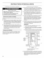
IMPORTANTES iNSTRUCTiONS DE SI_CURITi_
AVERTISSEM ENT • Pour r6duire le risque d'incendie, de choc 61ectrique ou de blessures Iors de I'utilisation
de la machine &glagons, il convient d'observer certaines pr6cautions 616mentaires :
[] Brancher sur une prise #,3 alveoles reliee & la terre. []
[] Ne pas enlever la broche de liaison & la terre.
[] Ne pas utiliser un adaptateur. []
[] Ne pas utiliser un c&ble de rallonge.
[] Utiliser deux ou plus de personnes pour deplacer et []
installer la machine & glagons.
Deconnecter la source de courant electrique avant le
nettoyage.
Deconnecter la source de courant electrique avant
I'entretien.
Replacer pieces et panneaux avant de faire la remise
en marche.
CONSERVEZ CES iNSTRUCTiONS
17

INSTRUCTIONS D'INSTALLATION
-_ .... . _ _ I _ _= _ _: l _ _,_ _ .... _
Risque du poids excessif
Utiliser deux ou plus de personnes pour d6placer et
installer la machine a gla£ons.
Le non-respect de cette instruction peut causer
une blessure au dos ou d'autre blessure.
Enl_vement des mat6riaux d'emballage
Enlever le ruban adhesif et la colle de la machine a glaI_ons avant
de I'utiliser.
• Pour enlever ce qui reste du ruban adhesif ou de la colle de la
surface exterieure de la machine a glagons, frotter la surface
vivement avec le pouce. La colle ou I'adhesif qui reste peut
_tre facilement enleve(e) en frottant une petite quantite de
savon &vaisselle liquide sur I'adhesif avec les doigts. Rincer
& I'eau tiede et essuyer.
• Ne pas utiliser d'instruments aceres, d'alcool a friction, de
liquides inflammables ou de nettoyants abrasifs pour enlever
le ruban adhesif ou la colle. Ne pas utiliser d'eau de Javel sur
les surfaces en acier inoxydable de la machine & glaI_ons.
Ces produits peuvent endommager la surface de votre
machine a glaI_ons.
Nettoyage avant I'utilisation
Apres avoir enleve tousles materiaux d'emballage, nettoyer
I'interieur de la machine & glaI;ons avant de I'utiliser. Voir les
instructions de nettoyage dans la section "Entretien de la
machine a glaI_ons".
• Pour assurer une bonne aeration de la machine & glaI;ons,
I'avant doit _tre completement degag& Les trois autres c6tes
et le dessus de la machine & glaI;ons peuvent se trouver dans
une cavite, mais I'installation doit permettre de tirer la
machine & glaI_ons vers I'avant pour I'entretien, si necessaire.
• Pour installer la machine & glaI;ons, il faut avoir un tuyau
souple d'alimentation en eau froide de V4"(6,35 mm) de dia.
ext. en cuivre avec un robinet d'arr_t et un systeme de
vidange par gravite ou une pompe & condensat pour pousser
I'eau vers un drain existant.
• Choisir un endroit bien aere oQ la temperature est superieure
&55°F (13°C) et inferieure & 100°F (38°C). Pour tirer le
meilleur rendement de I'appareil, la temperature ambiante
doit se situer entre 70°F (21°C) et 90°F (32°C). La machine &
glaI;ons doit _tre installee a un endroit protege contre les
elements, comme le vent, la pluie, les embruns ou les
egouttures.
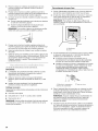
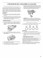
• Lorsque la machine & glaI;ons est installe sous un comptoir,
observer les dimensions d'ouverture recommandees. Placer
les composants electriques et de plomberie dans la zone
recommandee sur I'illustration.
REMARQUES:
Verifier que le cordon d'alimentation n'est pas coince
entre la machine a glaI_ons et le placard.
Verifier que le conduit de raccordement & la canalisation
d'alimentation en eau n'est pas coince entre la machine
glaI_ons et le placard.
Verifier que le tuyau d'evacuation (sur certains modeles)
n'est pas coince entre la machine & glagons et le placard.
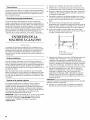
34"
(86,4 cm)
Min.
34V2"
(87,6 cm)
Max.
A. Zone recommand_e pour les composants
_lectriques et de plomberie
B. Niveau du plancher
A
B
II est recommande de choisir un emplacement oQ le plancher
est de niveau. II est important que la machine & glaI_ons soit
d'aplomb pour bien fonctionner. Au besoin, il est possible de
regler la hauteur de la machine & glaI;ons en changeant la
position des pieds de nivellement. Voir la section
"Nivellement".
18

Risque de choc _lectrique
Brancher sur une prise a 3 aIv_oles reli_e a la terre.
Ne pas enlever la broche de liaison a la terre.
Ne pas utiliser un adaptateur.
Ne pas utiliser un c&ble de rallonge.
Le non=respect de ces instructions peut causer
un d_c_s, un incendie ou un choc _lectrique.
Avant de deplacer la machine & glagons & son emplacement
definitif, il est important de s'assurer que le raccordement
electrique a et6 fait correctement :
IIfaut un circuit d'alimentation electrique CA seulement de
115 volts, 60 Hz, de 15 ou 20 amperes, mis & la terre
conformement aux instructions du Code national de I'electricit6
et des codes et r_glements Iocaux.
II est recommande de reserver un circuit special & la machine
glagons. Utiliser une prise oQ I'alimentation ne peut pas etre
coupee a I'aide d'un commutateur ou d'un interrupteur a tirage.
IMPORTANT • Si ce produit est connecte & une prise dotee d'un
disjoncteur de fuite &la terre, un declenchement intempestif peut
se produire et causer une perte de refroidissement. La qualite
des glagons peut en etre affectee. Si un declenchement
intempestif se produit et si les glagons semblent etre de pietre
qualite, jeter le tout.
M6thode de mise & la terre recommand_e
La machine a glagons doit etre reliee & la terre. La machine &
glagons comporte un cordon d'alimentation electrique &trois
broches pour la mise & la terre. Le cordon d'alimentation
electrique doit etre branche sur une prise de courant murale de
liaison & la terre configuration correspondante, & trois alveoles,
reliee &la terre conformement au Code national de I'electricite et
aux codes et reglements Iocaux. S'il n'y a pas de prise de
courant correspondante, il incombe au client de faire installer une
prise de courant murale & trois alveoles mise & la terre par un
electricien qualifi&
£ ,+,]%y.l ....... _ s "'+ 'I _[;llI" ,.........I ,II II I£= I ..........II,£ I elil @a/i
Une alimentation en eau froide avec une pression entre 30 et
120 Ib/po _(207 et 827 kPa) est necessaire pour faire fonctionner
la machine & glagons. Si vous avez des questions au sujet de la
pression de votre eau, appeler un plombier qualifie agree.
Alimentation en eau par osmose inverse
IMPORTANT •
• Les systemes de filtration de I'eau par osmose inverse
peuvent etre utilises uniquement avec des installations de
machine & glagons comportant une vidange par gravit& Un
systeme d'osmose inverse n'est pas recommande pour les
machines & glagons equipees d'une pompe de vidange.
• La pression de I'approvisionnement en eau provenant d'un
systeme d'osmose inverse allant au robinet d'arrivee d'eau
de la machine & glagons doit etre comprise entre 30 et 120 Ib/
po2(207 et 827 kPa).
Si un systeme de filtration de I'eau par osmose inverse est
raccorde & votre approvisionnement en eau froide, la pression de
I'eau au systeme d'osmose inverse doit etre de 40 & 60 Ib/po _
(276 & 414 kPa) minimum.
REMARQUE • Le systeme par osmose inverse doit fournir 1 gal.
(3,8 L) d'eau par heure &la machine &glagons pour un
fonctionnement approprie de la machine &glagons. Si I'on
souhaite un systeme d'eau par osmose inverse, il est
recommande d'utiliser uniquement un systeme de filtration de
I'eau par osmose inverse central, capable de maintenir
I'approvisionnement regulier en eau requis par la machine &
glagons. Les systemes par osmose inverse &capacite de robinet
ne peuvent pas maintenir I'approvisionnement regulier en eau
requis par la machine & glagons.
Si la pression de I'eau au systeme d'osmose inverse est
inferieure & 40 & 60 Ib/po _(276 &414 kPa) :
• Verifier si le filtre & sediment du systeme d'osmose inverse
est bloque et le remplacer si necessaire.
• Laisser le reservoir du systeme d'osmose inverse se remplir
apr_s une utilisation intense.
Si vous avez des questions au sujet de la pression de votre eau,
appeler un plombier qualifie agree.
IIest important que la machine & glagons soit d'aplomb pour bien
fonctionner. Selon I'endroit oQvous installez la machine &
glagons, vous pourrez avoir &effectuer plusieurs ajustements
pour la mettre d'aplomb. Vous pouvez egalement utiliser les
pieds de nivellement pour baisser la hauteur de la machine
glagons pour les installations sous comptoir.
Outillage n_cessaire :
Rassembler les outils et pieces necessaires avant de commencer
I'installation.
• Niveau de 9"
• Cle &molette
REMARQUE • II est plus facile d'ajuster les pieds de nivellement
si on se fait aider par une autre personne.
1. Deplacer la machine & glagons & son emplacement final.
REMARQUE •Dans le cas d'une installation encastree,
deplacer la machine & glagons le plus pros possible de son
emplacement final.
19

2=
3=
4.
Placer le niveau sur le dessus du produit pour voir si la
machine fl gla(_ons est d'aplomb d'avant en arriere et
transversalement.
Pousser vers le haut sur la partie superieure avant de la
machine a gla(_ons pour reperer les vis de nivellement qui se
trouvent sur le fond avant de la machine &gla(_ons.
Au moyen d'une cle a molette, modifier la hauteur des pieds
comme suit :
• Tourner le pied de nivellement vers la droite pour abaisser
ce c6te de la machine a gla£_ons.
• Tourner le pied de nivellement vers la gauche pour
soulever ce c6te de la machine a gla£_ons.
REMARQUE : La machine & glagons ne devrait pas osciller.
Utiliser des cales pour accroTtre la stabilite au besoin.
5. Pousser vers le haut sur la partie superieure arriere de la
machine & glagons pour reperer les pieds de nivellement qui
se trouvent sur le fond arriere de la machine a gla£;ons.
6. Suivre les instructions de I'etape 4 pour modifier la hauteur
des pieds.
7. Utiliser le niveau pour reverifier que la machine &gla£_onsest
d'aplomb d'avant en arriere et transversalement. Si elle n'est
pas d'aplomb, repeter les etapes 2 a 5. Si la machine est
d'aplomb, passer fl la section "Raccordement & la
canalisation d'eau".
Lire toutes les instructions avant de commencer.
IMPORTANT :
• L'installation de la plomberie doit _tre conforme au Code
International de plomberie et respecter les codes et
reglements Iocaux de plomberie.
• Utiliser un tuyau en cuivre ou le tuyau d'alimentation
Whirlpool, piece numero 8212547RP et verifier s'il y a des
fuites.
• Installer les tuyaux seulement I&oQ les temperatures
resteront au-dessus du point de congelation.
Outillage n_cessaire :
Rassembler les outils et pieces necessaires avant de commencer
I'installation.
• Tournevis a lame plate
• Cles plates de 7_e"et de V2"ou deux cles a molette
• Tourne-ecrou de V4"
REMARQUE : Ne pas utiliser de robinet d'arr_t de type perforant
ou & etrier de 3/16"(4,76 mm) qui reduit le debit d'eau et qui se
bouche plus facilement.
Raccordement du tuyau d'eau
1. Couper I'alimentation principale en eau. Ouvrir le robinet le
plus proche assez Iongtemps pour vider I'eau du tuyau.
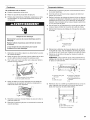
2. /_,I'aide d'un tuyau d'alimentation en cuivre de V2"avec une
valve d'arr_t tournee de un quart de tour ou I'equivalent,
raccorder la machine & gla£_onstel qu'illustr&
REMARQUE : Pour allouer un debit d'eau suffisant &la
machine & gla£_ons,un tuyau d'alimentation en cuivre de V2"
est recommand&
A
II I
B
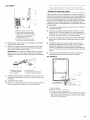
3=
4.
5.
A.Renflement
B.Ecrou
On est maintenant pr_t a connecter le tuyau en cuivre. Utiliser
un tuyau en cuivre souple de W' (6,35 mm) de diametre
exterieur pour I'alimentation en eau froide.
• S'assurer d'avoir la Iongueur necessaire pour le
raccordement. II faut s'assurer que les deux extremites
du tuyau en cuivre sont bien coupees a angle droit.
Installer le manchon et I'ecrou a compression sur le tuyau
en cuivre (voir I'illustration). Inserer I'extremite du tuyau
de sortie aussi profondement que possible dans
I'extremite de sortie eta I'equerre. Visser I'ecrou
compression sur I'extremite de la sortie a I'aide d'une cle
molette. Ne pas serrer a I'exces.
A. Manchon _ compression
B. E-crou de compression
C. Tuyau en cuivre
Placer I'extremite libre du tuyau dans un contenant ou evier
et retablir I'alimentation principale en eau pour nettoyer le
tuyau jusqu'& ce que I'eau en sorte claire. Fermer le robinet
d'arr_t sur le tuyau d'alimentation en eau.
REMARQUE : Toujours vidanger le tuyau d'alimentation en
eau avant de faire le raccordement final sur I'entree du
robinet pour emp_cher tout mauvais fonctionnement
eventuel du robinet.
Courber le tuyau de cuivre de fagon fl faire un raccordement
sur I'entree du robinet qui se trouve & I'arriere de la machine &
gla£_ons(voir I'illustration). Laisser un serpentin de tube en
cuivre pour permettre de sortir la machine &gla£_ons du
placard ou du mur en cas d'intervention de service.
20
La page est en cours de chargement...
La page est en cours de chargement...
La page est en cours de chargement...
La page est en cours de chargement...
La page est en cours de chargement...
La page est en cours de chargement...
La page est en cours de chargement...
La page est en cours de chargement...
La page est en cours de chargement...
La page est en cours de chargement...
La page est en cours de chargement...
La page est en cours de chargement...
-
 1
1
-
 2
2
-
 3
3
-
 4
4
-
 5
5
-
 6
6
-
 7
7
-
 8
8
-
 9
9
-
 10
10
-
 11
11
-
 12
12
-
 13
13
-
 14
14
-
 15
15
-
 16
16
-
 17
17
-
 18
18
-
 19
19
-
 20
20
-
 21
21
-
 22
22
-
 23
23
-
 24
24
-
 25
25
-
 26
26
-
 27
27
-
 28
28
-
 29
29
-
 30
30
-
 31
31
-
 32
32


KitchenAid KUIS18NNTS3 Le manuel du propriétaire
- Taper
- Le manuel du propriétaire
dans d''autres langues
Documents connexes
-
KitchenAid KUIO18NNVS0 Le manuel du propriétaire
-
KitchenAid KUIC15PLTS1 Le manuel du propriétaire
-
KitchenAid KUIS15NRTT2 Le manuel du propriétaire
-
KitchenAid KUIS18PNTW2 Le manuel du propriétaire
-
-
KitchenAid KUIC15NLSS0 Le manuel du propriétaire
-