KitchenAid KUIC15PLTS1 Le manuel du propriétaire
- Taper
- Le manuel du propriétaire

KJtchen_kid ®
ICE MAKER
For questions about features, operation/performance, parts, accessories or service, call: 1-800-422-1230 or visit out website at...
www.kitchenaid.com
In Canada, call for assistance, installation and service, call: 1-800-807-6777 or visit our website at...
www.KitchenAid.ca
MACHINE A GLA(_ONS
Au Canada, pour assistance, installation ou service composez le 1-800-807-6777 ou visitez notre site web &...
www.KitchenAid.ca
Table of Contents/Table des matieres ............................................................................. 2
2313814A

TABLEOF
ICE MAKER SAFETY ...................................................................... 3
INSTALLATION INSTRUCTIONS .................................................. 3
Unpack the Ice Maker .................................................................. 3
Location Requirements ................................................................ 4
Electrical Requirements ............................................................... 4
Water Supply Requirements ........................................................ 4
Leveling ........................................................................................ 5
Connect Water Supply ................................................................. 5
Drain Connection ......................................................................... 6
Ice Maker Door ............................................................................. 7
Normal Sounds ............................................................................ 8
ICE MAKER USE ............................................................................ 8
How Your Ice Maker Works ......................................................... 8
Using the Controls ....................................................................... 9
CONTENTS
ICE MAKER CARE .......................................................................... 9
Cleaning ........................................................................................ 9
Vacation and Moving Care ......................................................... 11
TROUBLESHOOTING .................................................................. 12
Ice Maker Operation ................................................................... 12
Ice Production ............................................................................ 12
Ice Quality ................................................................................... 13
Plumbing Problems .................................................................... 13
ASSISTANCE OR SERVICE ......................................................... 13
In the U.S.A................................................................................ 13
In Canada ................................................................................... 13
WAR RANTY .................................................................................. 14
TABLE DES MATIERES
S¢:CURIT¢: DE LA MACHINE A GLAQONS ................................ 15
INSTRUCTIONS D'INSTALLATION ............................................ 15
Deballage de la machine a gla(_ons........................................... 15
Exigences d'emplacement ......................................................... 16
Specifications electriques .......................................................... 16
Specifications de I'alimentation en eau ..................................... 16
Nivellement ................................................................................. 17
Raccordement a la canalisation d'eau ...................................... 17
Raccordement au conduit d'evacuation ................................... 18
Porte de la machine a gla9ons .................................................. 19
Sons normaux ............................................................................ 20
UTILISATION DE LA MACHINE A GLAQONS ............................ 21
Fonctionnement de la machine a gla(_ons................................. 21
Utilisation des commandes ........................................................ 21
ENTRETIEN DE LA MACHINE .,_GLAQONS .............................. 22
Nettoyage ................................................................................... 22
Precautions a prendre avant les vacances
ou un demenagement ................................................................ 24
DI:!:PANNAGE................................................................................. 25
Fonctionnement de la machine a gla(_ons................................. 25
Production de glat_ons............................................................... 25
Qualite des gla(_ons.................................................................... 26
Problemes de plomberie ............................................................ 26
ASSISTANCE OU SERVICE ......................................................... 26
GARANTIE ................................................................................. 27

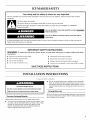
ICE MAKER SAFETY
Your safety and the safety of others are very important.
We have provided many important safety messages in this manual and on your appliance. Always read and obey all safety
messages.
This is the safety alert symbol.
This symbol alerts you to potential hazards that can kill or hurt you and others.
All safety messages will follow the safety alert symbol and either the word "DANGER" or "WARNING."
These words mean:
You can be killed or seriously injured if you don't immediately
follow instructions.
You can be killed or seriously injured if you don't follow
instructions.
All safety messages will tell you what the potential hazard is, tell you how to reduce the chance of injury, and tell you what can
happen if the instructions are not followed.
IMPORTANT SAFETY INSTRUCTIONS
WARNING: To reduce the risk of fire, electric shock, or injury when using your ice maker, follow these basic
precautions:
• Plug into a grounded 3 prong outlet.
• Do not remove ground prong.
• Do not use an adapter.
• Do not use an extension cord.
• Disconnect power before cleaning.
• Disconnect power before servicing.
• Replace all parts and panels before operating.
• Use two or more people to move and install ice maker.
SAVE THESE INSTRUCTIONS
INSTALLATION INSTRUCTIONS
Excessive Weight Hazard
Use two or more people to move and install ice maker.
Failure to do so can result in back or other injury.
Removing Packaging Materials
Do not use sharp instruments, rubbing alcohol, flammable
fluids, or abrasive cleaners to remove tape or glue. Do not
use chlorine bleach on the stainless steel surfaces of the ice
maker. These products can damage the surface of your ice
maker.
Cleaning Before Use
After you remove all of the packaging materials, clean the inside
of your ice maker before using it. See the cleaning instructions in
the Ice Maker Care section.
Remove tape and glue from your ice maker before using.
• To remove any remaining tape or glue from the exterior of the
ice maker, rub the area briskly with your thumb. Tape or glue
residue can also be easily removed by rubbing a small
amount of liquid dish soap over the adhesive with your
fingers. Wipe with warm water and dry.

Toensureproperventilationforyouricemaker,thefrontside
mustbecompletelyunobstructed.Theunitmaybeclosed-in
onthetopandthreesides,buttheinstallationshouldallow
theicemakertobepulledforwardforservicingifnecessary.
Installation of the ice maker requires a cold water supply inlet
of 1/4"(6.35 mm) OD soft copper tubing with a shutoff valve
and either a gravity-drain system or condensate pump to
carry the water to an existing drain.
Choose a well ventilated area with temperatures above 55°F
(13°C) and below 110°F (43°C). Best results are obtained
between 70°F (21°C) and 90°F (32°C).
This unit must be installed in an area protected from the
elements, such as wind, rain, water spray, or drip.
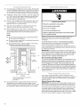
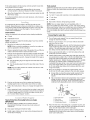
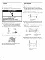
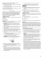
When installing the ice maker under a counter, follow the
recommended opening dimensions shown. Place electrical
and plumbing fixtures in the recommended location as
shown.
NOTE:
• Be sure the power supply cord is not pinched between
the ice maker and the cabinet.
• Be sure the water supply line is not pinched between the
ice maker and the cabinet.
• Be sure the drain line (on some models) is not pinched
between the ice maker and the cabinet.
34"
(86.4 cm)
Min.
341/2"
(87.6 cm)
Max.
_0 D-
281/2"
(72.4 cm)
_'_ 15"'_
(38,1 cm)
A.Recommended location for electrical
andplumbing fixtures
B.Floor level
You should choose a location where the floor is even. It is
important for the ice maker to be level in order to work
properly. If needed, you can adjust the height of the ice maker
by changing the height of the leveling legs. See "Leveling."
Electrical Shock Hazard
Plug into a grounded 3 prong outlet.
Do not remove ground prong.
Do not use an adapter.
Do not use an extension cord,
Failure to follow these instructions can result in death,
fire, or electrical shock.
Before you move your ice maker into its final location, it is
important to make sure you have the proper electrical
connection:
A 115 Volt, 60 Hz., AC only 15- or 20-amp electrical supply,
properly grounded in accordance with the National Electrical
Code and local codes and ordinances, is required.
It is recommended that a separate circuit, serving only your ice
maker, be provided. Use a receptacle which cannot be turned off
by a switch or pull chain.
IMPORTANT: If this product is connected to a GFCI (Ground
Fault Circuit Interrupter) protected outlet, nuisance tripping of the
power supply may occur, resulting in loss of cooling. Ice quality
may be affected. If nuisance tripping has occurred, and if the
condition of the ice appears poor, dispose of it.
Recommended grounding method
For your personal safety, this appliance must be grounded. This
appliance is equipped with a power supply cord having a 3 prong
grounding plug. To minimize possible shock hazard, the cord
must be plugged into a mating, 3 prong, grounding-type wall
receptacle, grounded in accordance with the National Electrical
Code and local codes and ordinances. Ifa mating wall receptacle
is not available, it is the personal responsibility of the customer to
have a properly grounded, 3 prong wall receptacle installed by a
qualified electrician.
A cold water supply with water pressure of between 30 and
120 psi (207 and 827 kPa) is required to operate the ice maker. If
you have questions about your water pressure, call a licensed,
qualified plumber.
Reverse Osmosis Water Supply
IMPORTANT: The pressure of the water supply coming out of a
reverse osmosis system going to the water inlet valve of the ice
maker needs to be between 30 and 120 psi (207 and 827 kPa).
If a reverse osmosis water filtration system is connected to your
cold water supply, the water pressure to the reverse osmosis
system needs to be a minimum of 40 to 60 psi (276 to 414 kPa).
The reverse osmosis system must provide 1 gal. (3.79L) of water
per hour to the ice maker for proper ice maker operation.

Ifthewaterpressuretothereverseosmosissystemislessthan
40to60psi(276to414kPa):
• Checktoseewhetherthesedimentfilterinthereverse
osmosissystemisblocked.Replacethefilterifnecessary.
• Allowthestoragetankonthereverseosmosissystemtorefill
afterheavyusage.
Ifyouhavequestionsaboutyourwaterpressure,callalicensed,
qualifiedplumber.
Itisimportantfortheicemakertobelevelinordertowork
properly.Dependinguponwhereyouinstalltheicemaker,you
mayneedtomakeseveraladjustmentstolevelit.Youmayalso
usethelevelinglegstolowertheheightoftheicemakerfor
undercounterinstallations.
Tools needed:
Gather the required tools and parts before starting installation.
• 9" level
• Adjustable wrench
NOTE: It is easier to adjust the leveling legs if you have another
person to assist you.
1. Move the ice maker to its final location.
NOTE: If this is a built-in installation, move the ice maker as
close as possible to the final location.
2. Place a carpenter's level on top of the product to see if the ice
maker is level from front to back and side to side.
3. Push up on the top front of the ice maker, and then locate the
leveling screws that are on the bottom front of the ice maker.
4. Using an adjustable wrench, change the height of the legs as
follows:
• Turn the leveling leg to the right to lower that side of the
ice maker.
• Turn the leveling leg to the left to raise that side of the ice
maker.
NOTE: The ice maker should not wobble. Use shims to add
stability when needed.
5. Push up on the top rear of the ice maker and locate the
leveling legs that are on the bottom rear of the ice maker.
6. Follow the instructions in Step 4 to change the height of the
legs.
7. Use a carpenter's level to recheck the ice maker to see that it
is even from front to back and side to side. If the ice maker is
not level, repeat steps 2 to 5. Ifthe ice maker is level, go to
the "Connect Water Supply" section.
Read all directions thoroughly before you begin.
IMPORTANT:
• Plumbing shall be installed in accordance with the
International Plumbing Code and any local codes and
ordinances.
• Use copper tubing and check for leaks.
• Install copper tubing only in areas where temperatures will
remain above freezing.
Tools needed:
Gather the required tools and parts before starting installation.
Read and follow the instructions provided with any tools listed
here.
• Flat-blade screwdriver
• 7/16"and 1/2"open-end wrenches or two adjustable wrenches
• 1/4"nut driver
• 1/4"drill bit
• Hand drill or electric drill properly grounded
NOTE: Your ice maker dealer has a kit available with a 1/4"
(6.35 mm) saddle-type shutoff valve, a union, and copper tubing.
Before purchasing, make sure a saddle-type valve complies with
your local plumbing codes. Do not use a piercing-type or 3/16"
(4.76 mm) saddle valve which reduces water flow and clogs more
easily.
Connecting the water line
1.
2.
Turn off main water supply. Turn on nearest faucet long
enough to clear line of water.
Find a 1/2"(12.70 mm) to 11/4'' (3.18 cm) vertical cold water
pipe near the ice maker.
NOTE: Horizontal pipe will work, but the following procedure
must be followed: Drill on the top side of the pipe, not the
bottom. This will help keep water away from the drill. This
also keeps normal sediment from collecting in the valve.
3. Using a grounded drill, drill a 1/4"(6.35 mm) hole in the cold
water pipe you have selected.
4. Fasten shutoff valve to cold water pipe with pipe clamp. Be
sure outlet end is solidly in the 1/4"(6.35 mm) drilled hole in the
water pipe and that the washer is under the pipe clamp.
Tighten packing nut. Tighten the pipe clamp screws carefully
and evenly so washer makes a watertight seal. Do not
overtighten the pipe clamp or you may crush cold water pipe
if it is soft copper tubing. Do not use a piercing-type or 3/16"
(4.76 mm) saddle-type valve which reduces water flow and
clogs more easily.
5. Now you are ready to connect the copper tubing. Use 1/4"
(6.35 mm) OD soft copper tubing for the cold water supply.
• Ensure that you have the proper length needed for the
job. Be sure both ends of the copper tubing are cut
square.
• Slip compression sleeve and compression nut on copper
tubing as shown. Insert end of tubing into outlet end
squarely as far as it will go. Screw compression nut onto
outlet end with adjustable wrench. Do not overtighten.
.......................... A
H ....... B
', .D
A.Cold waterpipe E.Compression nut
B.Pipe clamp F.Compression sleeve
C.Copper tubing G.Shutoff valve
D.Coupling (purchased) H.Packing nut
6.
Place the free end of the tubing into a container or sink, and
turn on main water supply and flush out tubing until water is
clear. Turn off shutoff valve on the water pipe.
NOTE: Always drain the water line before making the final
connection to the inlet of the water valve to avoid possible
water valve malfunction.

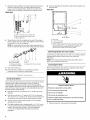
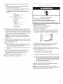
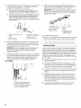
7. Bendthecoppertubingtomeetthewaterlineinletwhichis
locatedonthebackoftheicemakercabinetasshown.
Leaveacoilofcoppertubingtoallowtheicemakertobe
pulledoutofthecabinetorawayfromthewallforservice.
REAR VIEW
J
/
A
B
8=
A, Drain hose (drain pump models only)
B. Vent hose (drain pump models only)
C. Water supply line
Thread the nut onto the coupling on the end of the copper
tubing. Tighten the nut by hand. Then tighten it with a wrench
two more turns. Do not overtighten.
NOTE: To avoid rattling, be sure the copper tubing does not
touch the cabinet's side wall or other parts inside the cabinet.
A B C D E F G
A.Line to ice maker E.Ferrule
B.Nut (purchased) F Nut
C.Ferrule (purchased) G.Supplied line from ice maker
D. Coupling (purchased)
9. Turn shutoff valve ON.
fO. Check for leaks. Tighten any connections (including
connections at the valve) or nuts that leak.
Gravity Drain System
Connect the ice maker drain to your drain in accordance with all
state and local codes and ordinances. If the ice maker is
provided with a gravity drain system, follow these guidelines
when installing drain lines. This will help keep water from flowing
back into the ice maker storage bin and potentially flowing onto
the floor causing water damage.
• Drain lines must have a minimum of %" (15.88 mm) inside
diameter.
• Drain lines must have a 1" drop per 48" (2.54 cm drop per
122 cm) of run or 1/4"drop per 12" (6.35 mm per 30.48 cm) of
run and must not have low points where water can settle.
• The floor drains must be large enough to accommodate
drainage from all drains.
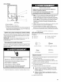
The ideal installation has a standpipe with a 11/2"(3.81 cm) to
2" (5.08 cm) PVC drain reducer installed directly below the
outlet of the drain tube as shown. You must maintain a
1" (2.54 cm) air gap between the drain hose and the
standpipe.
• It may be desirable to insulate the drain line thoroughly up to
the drain inlet.
SIDE VIEW
I
i-
3%"
(9.2 cm) Y
I
23" C
(58.4 cm)
D
2". 11/2''
(5 crn- 3.8 cm)
A. Drain hose
B. 1" (2.54 cm) air gap
C. PVC drain reducer
D. Center of drain should be 23" (58.4 cm) from front of door,
with or without the 3/4"(1.91 cm) panel on the dool: The
drain should also be centered from left to right (7 _6"
[18.56 cm] from either side of the ice maker),
Drain Pump System (on some models)
Connect the ice maker drain to your drain in accordance with the
International Plumbing Code and any local codes and
ordinances.
NOTE: If the drain hose becomes twisted and water cannot
drain, your ice maker will not work.
Connecting the Drain
After ensuring that the drain system is adequate, follow these
steps to properly place the ice maker:
Electrical Shock Hazard
Plug into a grounded 3 prong outlet.
Do not remove ground prong.
Do not use an adapter.
Do not use an extension cord,
Failure to follow these instructions can result in death,
fire, or electrical shock.
1. Plug ice maker into a grounded 3 prong outlet.

Excessive Weight Hazard
Use two or more people to move and install ice maker.
Failure to do so can result in back or other injury.
2. Style 1 - For gravity drain system, push the ice maker into
position so that the ice maker drain tube is positioned over
the PVC drain reducer. See "Gravity Drain System" earlier in
this section. Style 2 - For drain pump system connect the
drain pump outlet hose to the drain. See "Drain Pump
System" earlier in this section.
3. Recheck the ice maker to be sure that it is level. See
"Leveling."
4. If it is required by your local sanitation code, seal the cabinet
to the floor with an approved caulking compound after all
water and electrical connections have been made.
i_/, _,
TOOLS NEEDED:
Gather the required tools and parts before starting installation.
• %6" wrench • Flat putty knife
• 1/4"wrench • Phillips screwdriver
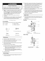
2. Remove the screws from the bottom of the opposite side of
the ice maker cabinet. Turn the top hinge upside down so
that the hinge pin points up. Place the hinge on the bottom
opposite side of the ice maker and tighten screws.
3. Remove the plastic hinge pin sleeve from the "old" bottom
hinge and replace it on the new bottom hinge pin.
4. Remove the "old" bottom hinge screws and hinge. Replace
the screws in the empty hinge holes.
5. Remove the screws from the top of the opposite side of the
ice maker cabinet. Turn the hinge upside down so that the
hinge pin points down. Place the hinge on the top opposite
side of the ice maker and tighten the screws.
6. Remove the top hinge pin.
Replace Door
1. Place plastic hinge pin sleeve in the top hinge hole on the
door. Align the door with the top hinge hole and replace the
top hinge pin.
2. Replace the handle and handle screws.
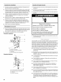
Top Hinge
.............. A
Hinge pin
5/16"Hex-head hinge screw
Handle screw End Cap screw
Remove Door
1. Unplug ice maker or disconnect power.
2. Remove the handle screws and handle (on some models).
Keep the parts together and set them aside.
3. Remove the hinge pin from the top hinge.
4. Remove the door from the hinges and screw the top hinge pin
back into the top hinge.
5. Reverse the door end caps as follows:
• Remove both the screws and end caps (top and bottom).
• Move the top end cap diagonally to the opposite side's
bottom corner, keeping the straight side of the end cap
facing the front of the ice maker
• Move the bottom end cap diagonally to the opposite
side's top corner, keeping the straight side of the end cap
facing the front of the ice maker.
6. Set the door aside.
Reverse Hinges
1. Unscrew and remove the top hinge. Replace the screws in
the empty hinge holes.
A. Hinge pin
B. Hinge pin sleeve
Bottom Hinge
C. Hinge
D. Hex-head hinge screw
-o iiiiiiiii
L
A. Hex-head hinge screw C. Hinge
B. Hinge pin sleeve D. Hinge pin

Reverse Door Catch
1. Remove the hole plugs from the opposite side of the door
and set aside.
2. Remove the screws from the magnetic door catch and
replace it on the opposite side of the door.
3. Push the hole plugs into place on the opposite side of the
door.
Electrical Shock Hazard
Plug into a grounded 3 prong outlet.
Do not remove ground prong.
Do not use an adapter.
Do not use an extension cord,
Failure to follow these instructions can result in death,
fire, or electrical shock.
4. Plug in ice maker or reconnect power.
Your new ice maker may make sounds that are not familiar to
you. Because the sounds are new to you, you might be
concerned about them. Most of the new sounds are normal. Hard
surfaces such as floors, walls and cabinets can make the sounds
seem louder than they actually are. The following describes the
kinds of sounds that might be new to you and what may be
making them.
• You will hear a buzzing sound when the water valve opens to
fill the water reservoir for each cycle.
• Rattling noises may come from the flow of the refrigerant or
the water line. Items stored on top of the ice maker can also
make noises.
• The high-efficiency compressor may make a pulsating or high
pitched sound.
• Water running over the evaporator plate may make a
splashing sound.
• Water running from the evaporator plate to the water reservoir
may make a splashing sound.
• As each cycle ends, you may hear a gurgling sound due to
the refrigerant flowing in your ice maker.
• You may hear air being forced over the condenser by the
condenser fan.
• During the harvest cycle, you may hear a "thud" when the ice
sheet slides from the evaporator onto the cutter grid.
• When you first start the ice maker, you may hear water
running continuously. The ice maker is programmed to run a
rinse cycle before it begins to make ice.
ICE MAKER USE
When you first start your ice maker, the water pan will fill and the
system will rinse itself before starting to make ice. The rinsing
process takes about 5 minutes.
Under normal operating conditions, the ice maker will cycle at
preset temperatures. The ice level sensor located in the ice
storage bin will monitor the ice levels.
IMPORTANT:
• If the water supply to the ice maker is turned off, be sure to
set the ice maker control to OFE
• The ice maker is designed to make clear ice from the majority
of water sources on a daily basis. If your results are
unsatisfactory, your water may need to be filtered or treated.
The Ice Making Process
1. Water is constantly circulated over a freezing plate. As the
water freezes into ice, the minerals in the water are rejected.
This produces a sheet of ice with a low mineral content.
2. When the desired thickness is reached, the ice sheet is
released and slides onto a cutter grid. The grid divides the
sheet into individual cubes.
3. The water containing the rejected minerals is drained after
each freezing cycle.
4. Fresh water enters the machine for the next ice making cycle.
5. Cubes fall into the storage bin. When the bin is full, the ice
maker shuts off automatically and restarts when more ice is
needed. The ice bin is not refrigerated, and some melting will
occur. The amount of melting varies with room temperature.
NOTE: As the room and water temperatures vary, so will the
amount of ice produced and stored. This means that higher
operating temperatures result in reduced ice production.

1. Tostartthenormalicemakingcycle,selectON.
2. Tostopicemakeroperation,selectOFR
Holiday Clean/
On/Off Mode Service Reset
0000
NOTE:
• Pressing the ON/OFF switch does not shut off power to
the ice maker.
• Allow 24 hours to produce the first batch of ice. Discard
the first batch produced.
Holiday Mode
The Holiday Mode feature is designed for the traveler or for those
whose religious observances require turning off the lights and the
ice maker. By selecting this feature, ice production will be
disabled and the interior lights will turn off.
Press and hold the Holiday Mode button to turn on the Holiday
Mode feature. Press and hold the button again to turn off the
feature.
Service
The service light indicates when service is needed. If the service
light turns on, turn the ice maker off and back on. If the service
light turns on again, call for service.
Clean/Reset
The Cleaning/Reset Status light will help you know when it is time
to clean your ice maker. The light will change from green to
yellow. This tells you it is almost time to clean your ice maker. It is
recommended that you clean the ice maker when the status light
changes to red OR ice production decreases significantly. To
clean your ice maker, see "Ice Maker System."
ICE MAKER CARE
The ice making system and the air cooled condenser need to be
cleaned regularly for the ice maker to operate at peak efficiency
and to avoid premature failure of system components. See the
"Ice Maker System" and the "Condenser" sections.
Exterior Surfaces
Wash the exterior enamel surfaces and gaskets with warm water
and mild soap or detergent. Wipe and dry. Regular use of a good
household appliance cleaner and wax will help protect the finish.
Do not use abrasive cleaners on enamel surfaces as they may
scratch the finish.
For products with a stainless steel exterior, use a clean sponge or
soft cloth and a mild detergent in warm water. Do not use
abrasive or harsh cleaners. Do not use chlorine bleach on the
stainless steel surfaces.
Ice Maker System
Minerals that are removed from water during the freezing cycle
will eventually form a hard scaly deposit in the water system.
Cleaning the system regularly helps remove the mineral scale
buildup. How often you need to clean the system depends upon
how hard your water is. With hard water of 15 to 20 grains/gal.
(4 to 5 grains/liter), you may need to clean the system as often as
every 6 months.
NOTE: Use one 16 oz (473 mL) bottle of approved ice maker
cleaner. To order, call 1-800-442-9991 and ask for Part Number
4396808. In Canada, call 1-800-807-6777.
1. Push the selector switch to OFE
2. Wait 5 to 10 minutes for the ice to fall into the storage bin.
Remove all ice from the storage bin.
3. Unscrew the drain cap from the bottom of the water pan
located inside the storage bin as shown. Allow the water to
drain completely.
4. Replace the drain cap securely on the water pan. If the drain
cap is loose, water will empty from the water pan and you will
have either thin ice or no ice.
5. Read and follow all handling information on the cleaner bottle
before completing the steps below. Use one 16 oz (473 mL)
bottle of approved ice maker cleaner.
6. Pour one bottle of solution into the water pan. Fill the bottle
twice with tap water and pour it into the water pan.
B ..............
t -_\ qo \ -j
......... ......................S
A. Water pan
B. Water pan thumb screws
C. Drain cap
7.
8=
Press and hold the CLEAN button. See "Using the Controls."
The light will blink, indicating that the cleaning cycle is in
process. When the indicator light turns green (approximately
70 minutes), the cleaning cycle is complete. During the
cleaning cycle, the system will both clean and rinse itself.
After the cleaning cycle is complete, remove the drain cap
from the water pan. Look for any cleaning solution left in the
water pan. If cleaning solution drains from the water pan, you
should run the clean cycle again. Be sure to replace the drain
cap securely on the water pan. Ifthe drain cap is loose, water
will empty from the water pan and you will have either thin ice
or no ice.
NOTE: Severe scale buildup may require repeated cleaning with
a fresh quantity of cleaning solution.
9. Push the selector switch to ON to resume ice production.

Condenser
A dirty or clogged condenser:
• Obstructs proper airflow.
• Reduces ice making capacity.
• Causes higher than recommended operating temperatures
which may lead to component failure.
Electrical Shock Hazard
Disconnect power before cleaning.
Replace all parts and panels before operating.
Failure to do so can result in death or electrical shock.
1. Unplug ice maker or disconnect power.
2. Remove the two screws in the lower access panel and the
two screws from the base grille area of the front panel
support. Pull forward to remove the lower access panel.
3. Pull the bottom forward and then pull down to remove the
lower access panel.
Interior Components
1. Unplug ice maker or disconnect power.
2. Open the storage bin door and remove any ice that is in the
bin.
3. Remove the drain cap from the water pan and drain
thoroughly. Replace the drain cap securely on the water pan.
If the drain cap is loose, water will empty from the water pan,
and you will have either thin ice or no ice.
4. Remove the two screws that hold the cutter grid cover in
place and remove the cutter grid cover.
5. Unplug the wiring harness from the left side of the cutter grid.
A. Cutter grid cover
B. Screws
6. Unplug the ice level sensor from the right side of the cutter
grid. Pull the ice level sensor down and forward away from
the cutter grid.
7. Remove the right-hand and left-hand screws. Lift the cutter
grid up and out.
NOTE: Make sure the plastic spacer from the right-hand side
of the cutter grid bracket stays with the cutter grid.
4. Remove dirt and lint from the condenser fins and the unit
compartment with a brush attachment on a vacuum cleaner.
5. Replace the lower access panel using the four screws.
6. Plug in ice maker or reconnect power.
8.
\
A.Cutter grid harness D.Ice levelsensor harness
B.Screw E.Plasticspacer
C.Cutter grid F. Screw
Remove the two thumb screws that hold the water pan in
place. Push down with one hand on the front of the pan while
pulling forward on the bottom back side.
B'--
"1_\1k
A.Waterpan
B.Waterpan thumb screws
C.Drain cap
10

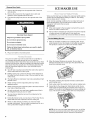
g,
Remove, clean and replace the ice scoop and ice scoop
holder.
• After removing the ice scoop, remove the holder by
removing the two thumb screws.
• Wash the ice scoop holder along with the other interior
components using the following instructions.
• Replace the ice scoop holder by replacing the thumb
screws.
A. Thumb screw
B. Ice scoop holder
10. Wash the interior components (cutter grid, exterior of hoses,
and water pan) and the storage bin, door gasket, ice scoop,
and ice scoop holder with mild soap or detergent and warm
water. Rinse in clean water. Then clean the same parts with a
solution of 1 tbs (15 mL) of household bleach in 1 gal. (3.8 L)
warm water. Rinse again thoroughly in clean water.
NOTE: Do not remove hoses. Do not wash plastic parts in
dishwasher. They cannot withstand temperatures above
145°F (63°C).
11. Replace water pan by pushing back on the bottom with one
hand while pushing up and back on thetop. Secure the water
pan by replacing both screws.
12. Check the following:
• Drain cap from the water pan is securely in place. If the
drain cap is loose, water will empty from the water pan,
and you will have either thin ice or no ice.
• Hose from water pan is inserted into storage bin drain
opening.
13. Slide the cutter grid back into place and secure it by
replacing the right-hand screw and plastic spacer. Then
tighten the left-hand screw. Reconnect the cutter grid
harness and the ice level sensor harness.
14. Replace the cutter grid cover and the two screws.
15. Plug in ice maker or reconnect power.
_ _, _ ._ ,_ , _ hi¸ _ y-,_
Electrical Shock Hazard
Disconnect power before servicing.
Replace all parts and panels before operating.
Failure to do so can result in death or electrical shock.
To shut down the ice maker:
1. Unplug ice maker or disconnect power.
2. Remove all ice from storage bin.
3. Shut off the water supply.
4. Remove the two screws in the lower access panel and the
two screws from the base grille area of the front panel
support. Pull forward to remove the lower access panel.
5. Disconnect the inlet and outlet lines to water valve. Allow
these lines to drain and then reconnect to the valve.
6. Replace lower access panel and screws.
7. Drain water from water pan by removing the drain cap.
8. If the room temperature will drop below 32°F (0°C), remove
water from the drain line.
For ice makers with a drain pump installed:
• Plug in ice maker or reconnect power.
• Turn ice maker off and remove all remaining ice from ice
bin.
• Pour 1 qt (0.95 L) of water into the ice bin near the drain
and let the unit stand for approximately 5 minutes. This
will allow the water in the bin to drain into the drain pump
so that the pump will remove the remaining water from
the ice bin and the drain pump.
• Unplug ice maker or disconnect power.
9. Before using again, clean the ice maker and storage bin.
10. Plug into a grounded 3 prong outlet.
NOTE: All components of the ice maker are permanently
lubricated at the factory. They should not require any additional
oiling throughout the normal life of the machine.
11

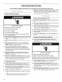
TROUBLESHOOTING
Try the solutions suggested here first in order to avoid the cost of an unnecessary service call.
• Is there ice between the evaporator plate and the cutting
_i_.t:4b_'T grid? Check to be sure that the ice maker is level. See
...... "Leveling." If the ice maker is level, and the problem persists,
Your ice maker will not operate run a cleaning cycle. See "Cleaning."
Electrical Shock Hazard
Plug into a grounded 3 prong outlet.
Do not remove ground prong.
Do not use an adapter.
Do not use an extension cord.
Failure to follow these instructions can result in death,
fire, or electrical shock.
Is the power cord plugged in? Plug into a grounded 3 prong
outlet.
Is the control set to ON? Be sure that the control is set to
ON.
Has a household fuse blown, or has a circuit breaker
tripped? Replace the fuse or reset the circuit breaker. If the
problem continues, call an electrician.
is the room temperature cooler than normal? Room
temperature must be above 55°F (13°C). Otherwise, bin
thermostat may sense cold room temperature and shut off
even though the bin is not full of ice. Also, unit may not restart
once it does shut off.
Does the red light come on when the Clean button is
pushed? The ice maker is receiving power but may need
cleaning. See "Cleaning."
Does the ice maker have a drain pump? Ifthere was a large
amount of water added to the ice maker, wait a few minutes
for the drain pump to clear. If there is still water in the bin,
check to see whether the drain hose is kinked.
Ice maker seems noisy
• Is water being circulated through the ice maker? This is •
normal operation, Water is added once per ice-making cycle,
• Is the water in the reservoir overflowing? This is normal,
This overflow helps to purge minerals that were removed from
the water during the ice making process.
• Is there a "whooshing" sound? Check the following things:
• Make sure that the water supply is hooked up and turned
on.
• Make sure that the drain cap is tight and the water drain
pan pump is securely attached to the water pan,
Ice maker runs but produces no ice
• Is the control set to ON? Be sure that the control is set to
ON.
• Is the water supply connected? Make sure the water supply
is properly connected and turned on.
• Is the drain cap securely in place? If the drain cap is loose,
water will empty from the water pan, and you will have either
thin ice or no ice. Tighten the drain cap.
• Is there debris in the drain tube? Clean the drain tube.
• Is there a kink in the drain line? Be sure that there are no
kinks in the line.
• Is the service light flashing on and off continually? Call for
service.
Ice maker runs but produces very little ice
• Is the room temperature hotter than normal? Room
temperatures of more than 90°F (32°C) will normally reduce
ice production.
Electrical Shock Hazard
Disconnect power before servicing.
Replace all parts and panels before operating.
Failure to do so can result in death or electrical shock.
Is the condenser dirty? Dirt or lint may be blocking the
airflow through the condenser. See "Condenser."
Is there scale buildup in the ice maker? If there is white
scale buildup in the ice maker's water or freezing system, you
should clean the ice maker. See "Interior Components" in the
"Cleaning" section.
Is the drain cap securely in place? If the drain cap is loose,
water will empty from the water pan, and you will have either
thin ice or no ice, Tighten the drain cap if it is loose.
12

Grid is not cutting ice sheets
Is the cutter grid securely in place? Check the cutter grid
harness plug to make sure the connection is intact. See
"Interior Components" section of "Cleaning" for instructions
on cutter grid removal.
Off taste, odor or gray color in the ice
• Is there unusually high mineral content in the water
supply? The water may need to be filtered or treated.
• Is there mineral scale buildup? Clean your ice maker. See
"Ice Maker System" in the "Cleaning" section.
• Are there food items stored in the ice bin? De not store any
foods in the ice bin.
• Were all the packaging materials removed? Make sure that
all packaging materials were removed at the time of
installation.
Thin, soft or clumps of ice
• Is there unusually high mineral content in the water
supply? The water may need to be filtered or treated.
• Is there mineral scale buildup? Clean your ice maker. See
"Ice Maker System" in the "Cleaning" section.
• Are there clumps of ice in the bin? If ice is not used
regularly it will melt and form clumps. Break the clumps with
the ice scoop provided.
Excessive Weight Hazard
Use two or more people to move and install ice maker.
Failure to do so can result in back or other injury.
• Is the drain hose aligned over the drain? Move the ice
maker to align the drain. See "Water Supply Connection."
NOTE: Service technicians can not repair plumbing problems
outside of the ice maker. Call a licensed, qualified plumber.
ASSISTANCE OR SERVICE
Before calling for assistance or service, please check
"Troubleshooting." It may save you the cost of a service call. If
you still need help, follow the instructions below.
When calling, please know the purchase date and the complete
model and serial number of your appliance. This information will
help us to better respond to your request.
If you need replacement parts
If you need to order replacement parts, we recommend that you
only use factory specified parts. Factory specified parts will fit
right and work right because they are made with the same
precision used to build every new KITCHENAID®appliance.
To locate factory specified parts in your area, call us or your
nearest designated service center.
Call the KitchenAid Customer eXperience Center
toll free: 1-800-422-1230.
Our consultants provide assistance with:
• Features and specifications on our full line of appliances.
• Installation information.
• Use and maintenance procedures.
• Accessory and repair parts sales.
• Specialized customer assistance (Spanish speaking, hearing
impaired, limited vision, etc.).
Referrals to local dealers, repair parts distributors, and
service companies. KitchenAid designated service
technicians are trained to fulfill the product warranty and
provide after-warranty service, anywhere in the United States.
To locate the KitchenAid designated service company in your
area, you can also look in your telephone directory Yellow
Pages.
For further assistance
If you need further assistance, you can write to KitchenAid with
any questions or concerns at:
KitchenAid Brand Home Appliances
Customer eXperience Center
553 Benson Road
Benton Harbor, M149022-2692
Please include a daytime phone number in your correspondence.
Call the KitchenAid Canada Customer Interaction Centre toll free:
1-800-807-6777.
Our consultants provide assistance with:
• Use and maintenance procedures.
• Accessory and repair parts sales.
• Referrals to local dealers, repair parts distributors, and
services companies. KitchenAid Canada designated service
technicians are trained to fulfill the product warranty and
provide after-warranty service, anywhere in Canada.
For further assistance
If you need further assistance, you can write to KitchenAid
Canada with any questions or concerns at:
Customer Interaction Centre
KitchenAid Canada
1901 Minnesota Court
Mississauga, Ontario L5N 3A7
Please include a daytime phone number in your correspondence.
13

KITCHENAID ®ICE MAKER WARRANTY
ONE YEAR LIMITED WARRANTY
For one year from the date of purchase, when this major appliance is operated and maintained according to instructions attached to or
furnished with the product in a residential setting, KitchenAid or KitchenAid Canada (hereafter "KitchenAid") will pay for factory
specified parts and repair labor to correct defects in materials or workmanship. Service must be provided by a KitchenAid designated
service company.
SECOND THROUGH FIFTH YEAR LIMITED WARRANTY ON SEALED REFRIGERATION SYSTEM PARTS
In second through fifth years from the date of purchase, when this product is operated in a residential setting, and is maintained
according to the instructions furnished with the product, KitchenAid will pay for replacement parts and repair labor costs to correct
defects in materials or workmanship in the sealed refrigeration system. These parts are compressor, evaporator, condenser, dryer/
strainer, and connecting tubing. Service must be performed by a KitchenAid designated service company.
ITEMS KITCHENAID WILL NOT PAY FOR
1. Service calls to correct the installation of your major appliance, to instruct you how to use your major appliance, to replace or repair
house fuses or to correct house wiring or plumbing.
2. Service calls to repair or replace appliance light bulbs, air filters or water filters. Those consumable parts are excluded from warranty
coverage.
3. Repairs when your major appliance is used for other than normal, single-family household use.
4. Damage resulting from accident, alteration, misuse, abuse, fire, flood, acts of God, improper installation, installation not in
accordance with electrical or plumbing codes, or use of products not approved by KitchenAid.
5. Any food loss due to refrigerator or freezer product failures.
6. Replacement parts or repair labor costs for units operated outside the United States or Canada.
7. Pickup and delivery. This major appliance is designed to be repaired in the home.
8. Repairs to parts or systems resulting from unauthorized modifications made to the appliance.
9. Expenses for travel and transportation for product service in remote locations.
10. The removal and reinstallation of your appliance if it is installed in an inaccessible location or is not installed in accordance with
published installation instructions.
DISCLAIMER OF IMPLIED WARRANTIES; LIMITATION OF REMEDIES
CUSTOMER'S SOLE AND EXCLUSIVE REMEDY UNDER THIS LIMITED WARRANTY SHALL BE PRODUCT REPAIR AS PROVIDED
HEREIN. IMPLIED WARRANTIES, INCLUDING WARRANTIES OF MERCHANTABILITY OR FITNESS FOR A PARTICULAR PURPOSE,
ARE LIMITED TO ONE YEAR OR THE SHORTEST PERIOD ALLOWED BY LAW. KITCHENAID SHALL NOT BE LIABLE FOR
INCIDENTAL OR CONSEQUENTIAL DAMAGES. SOME STATES AND PROVINCES DO NOT ALLOW THE EXCLUSION OR LIMITATION
OF INCIDENTAL OR CONSEQUENTIAL DAMAGES, OR LIMITATIONS ON THE DURATION OF IMPLIED WARRANTIES OF
MERCHANTABILITY OR FITNESS, SO THESE EXCLUSIONS OR LIMITATIONS MAY NOT APPLY TO YOU. THIS WARRANTY GIVES
YOU SPECIFIC LEGAL RIGHTS AND YOU MAY ALSO HAVE OTHER RIGHTS, WHICH VARY FROM STATETO STATE OR PROVINCE
TO PROVINCE.
Outside the 50 United States and Canada, this warranty does not apply. Contact your authorized KitchenAid dealer to determine if
another warranty applies.
If you need service, first see the "Troubleshooting" section of the Use & Care Guide. After checking "Troubleshooting," additional help
can be found by checking the "Assistance or Service" section or by calling KitchenAid. In the U.S.A., call 1-800-422-1230. In Canada,
call 1-800-807-6777. 9/05
Keep this book and your sales slip together for future
reference. You must provide proof of purchase or installation
date for in-warranty service.
Write down the following information about your major appliance
to better help you obtain assistance or service if you ever need it.
You will need to know your complete model number and serial
number. You can find this information on the model and serial
number label located on the product.
Dealer name
Address
Phone number
Model number
Serial number
Purchase date
14

P P ,_
SECURITE DE LA MACHINE A GLA( ONS
Votre s6curit6 et celle des autres est tr6s importante.
Nous donnons de nombreux messages de securite importants dans ce manuel et sur votre appareil menager. Assurez-vous de
teujours lire tousles messages de securit6 et de vous y conformer.
Voici le symbole d'alerte de securit&
Ce symbole d'alerte de securit6 vous signale les dangers potentiels de deces et de blessures graves & vous
et & d'autres.
Tousles messages de securite suivront le symbele d'alerte de securite et le mot "DANGER" ou
"AVERTISSEMENT". Ces mots signifient :
Risque possible de deces ou de blessure grave si vous ne
suivez pas immediatement lee instructions.
Risque possible de deces ou de blessure grave si vous
ne euivez pas lee instructions.
Tousles messages de securite vous diront quel est le danger potentiel et vous disent comment reduire le risque de blessure et
ce qui peut se produire en cas de non-respect des instructions.
IMPORTANTES INSTRUCTIONS DE SECURIT¢::
AVERTISSEIVlENT : Pour r6duire le risque d'incendie, de choc 61ectrique ou de blessures Iors de I'utilisation
de la machine & glagons, il convient d'observer certaines pr6cautions 616mentaires :
• Brancher sur une prise & 3 alveoles reliee & la terre.
• Ne pas enlever la broche de liaison a la terre.
[] Ne pas utiliser un adaptateur.
• Ne pas utiliser un c&ble de rallonge.
• Utiliser deux ou plus de personnes pour deplacer et
installer la machine & glagons.
[] Deconnecter la source de courant electrique avant le
nettoyage.
[] Deconnecter la source de courant electrique avant
I'entretien.
• Replacer pieces et panneaux avant de faire la remise
en marche.
CONSERVEZ CES INSTRUCTIONS
INSTRUCTIONS D'INSTALLATION
Risque du poids excessif
Utiliser deux ou plus de pereonnes pour deplacer et
installer la machine a glagons.
Le non-respect de cette instruction peut causer
une blessure au dos ou d'autre blessure.
Enl_vement des mat6riaux d'emballage
Ne pas utiliser d'instruments aceres, d'alcool a friction, de
liquides inflammables ou de nettoyants abrasifs pour enlever
le ruban adhesif ou la colle. Ne pas utiliser d'eau de Javel sur
les surfaces en acier inoxydable de la machine a glagons.
Ces produits peuvent endommager la surface de votre
machine a glagons.
Nettoyage avant I utilisation
Apres avoir enleve tous les materiaux d'emballage, nettoyer
I'interieur de la machine a glagons avant de I'utiliser. Voir les
instructions de nettoyage dans la section "Entretien de la
machine a glagons".
Enlever le ruban adhesif et la colle de la machine a glagons avant
de I'utiliser.
• Pour enlever ce qui reste du ruban adhesif ou de la colle de
la surface exterieure de la machine & glagons, frotter la
surface vivement avec le pouce. La colle ou I'adhesif qui
reste peut _tre facilement enleve(e) en frottant une petite
quantite de liquide vaisselle sur I'adhesif avec les doigts.
Rincer a I'eau tiede et essuyer.
15

I Ljio# ioi0_,> :I ' ..............
...........;de" _ {_< ? I_,;_<:071 ¢:_II.!]
Pour assurer une bonne a@ation de la machine £ glagons,
I'avant dolt _tre completement degage. Les autres c6tes et le
dessus de I'appareil peuvent _tre dissimules, mais
I'installation dolt permettre de tirer la machine a glagons vers
I'avant pour I'entretien, si necessaire.
Pour installer la machine a glagons, il faut avoir un tuyau
souple d'alimentation en eau froide de 1/4"(6,35 mm) de
diametre exterieur en cuivre avec un robinet et un systeme de
vidange par gravite ou une pompe a condensats pour
pousser I'eau vers un drain existant
Choisir un endroit bien aere ou la temperature est sup@ieure
55°F (13°C) et inf@ieure a 110°F (43°C). Pour tirer le
meilleur rendement de I'appareil, la temperature ambiante
dolt se situer entre 70°F (21°C) et 90°F (32°C).
Cet appareil dolt _tre installe a un endroit protege contre les
elements, comme le vent, la pluie, les embruns ou les
egouttures.
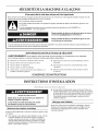
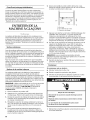
Lorsque I'appareil est installe sous un comptoir, observer les
dimensions d'ouverture indiquees. Placer les composants
electriques et de plomberie dans la zone recommandee sur
I'illustration.
REMARQUE:
• V@ifier que le cordon d'alimentation n'est pas coince
entre la machine a glagons et le placard.
• V@ifier que le conduit de raccordement a la canalisation
d'eau n'est pas coince entre la machine a gla(_ons et le
placard.
• V@ifier que le tuyau d'evacuation (sur certains modeles)
n'est pas coince entre la machine a gla(_ons et le placard.
34"
(86,4 cm)
Min.
341/2 ''
(87,6 cm)
Max,
_1 I-
281/2''
(72,4 cm)
_-'_ 15"
(38,1 cm)
A. Zone recommand_e pour lee composants
_lectriques et de plomberie
B. Niveau du plancher
II est recommande de choisir un emplacement ou le plancher
est de niveau. IIest important que la machine a glagons soit
d'aplomb pour bien fonctionner. Au besoin, il est possible de
regler la hauteur de la machine a glagons en changeant la
position des pieds de nivellement Voir la section
"Nivellement".
},ii 1){?<) 111 d;_ )T}._{; I ;:<:I ']<:I<I{Lf.._
Risque de choc electrique
Brancher sur une prise a 3 alveoles reliee a la terre.
Ne pae enlever la broche de liaison a la terre.
Ne pas utiliser un adaptateur.
Ne pas utiliser un cable de rallonge.
Le non-respect de ces instructions peut causer
un deces, un incendie ou un choc electrique.
Avant de deplacer la machine a gla(_ons a sa place definitive, il
faut s'assurer que le raccordement electrique a ete fait
correctement.
IIfaut un circuit d'alimentation electrique CA seulement de
115 volts, 60 Hz, de 15 ou 20 amperes, mis a la terre
conformement aux instructions du Code national de I'electricite
et des codes et reglements Iocaux.
II est recommande de reserver un circuit special a la machine
glagons. Utiliser une bofte ot] I'alimentation ne peut pas _tre
coupee a I'aide d'un commutateur ou d'un interrupteur a tirage.
IMPORTANT : Si ce produit est connecte a une prise protegee
par un disjoncteur de fuite a la terre, un declenchement
intempestif peut se produire et causer une perte de
refroidissement La qualite des gla(_ons peut en _tre affectee. Si
un declenchement intempestif se produit et si les gla(_ons
semblent de pietre qualite, jeter le tout.
M_thode de mise a la terre recommand_e
Pour votre propre securite, cet appareil dolt _tre mis a la terre.
L'appareil comporte un cordon d'alimentation electrique a trois
broches pour la mise a la terre. Pour minimiser les risques de
choc electrique, le cordon d'alimentation electrique dolt _tre
branche sur une prise de courant murale de configuration
correspondante, a trois alveoles, reliee a la terre conformement
au Code national de I'electricite et aux codes et reglements
Iocaux. S'il n'y a pas de prise de courant correspondante, il
incombe au client de faire installer une prise de courant murale
trois alveoles mise a la terre par un electricien qualifie.
< .-,'1 :; ,., -, ,. iilllli_lOll[i:_<! +_111(!'I {) U
.'_I.)1_I l<4[l{llSd _ ">' " ' _ ....
Une alimentation en eau froide avec une pression entre 30 et
120 Ib/po 2(207 et 827 kPa) est necessaire pour faire fonctionner
la machine a glagons. Si vous avez des questions au sujet de la
pression de votre eau, appeler un plombier qualifie agree.
Alimentation en eau par osmose inverse
IMPORTANT : La pression de I'alimentation en eau entre le
systeme d'osmose inverse et la valve d'arrivee d'eau de la
machine a gla(;ons dolt _tre entre 30 et 120 Ib/po _(207 et
827 kPa).
Si un systeme de purification de I'eau par osmose inverse est
raccorde a votre alimentation en eau froide, la pression de I'eau
au systeme dolt _tre d'un minimum de 40 a 60 Ib/po _(276
414 kPa). Le systeme d'osmose inverse dolt fournir 1 gal. (3,79 L)
d'eau par heure pour un fonctionnement correct de la machine
glagons.
16

Si la pression de I'eau au syst_me d'osmose inverse est
inferieure a 40 a 60 Ib/po 2(276 a 414 kPa) :
• V@ifier si le filtre du syst_me d'osmose inverse est bloque et
le remplacer si necessaire.
• Laisser le reservoir du systeme d'osmose inverse se remplir
apres une utilisation intense.
Si vous avez des questions au sujet de la pression de votre eau,
appeler un plombier qualifie agree.
IIest important que la machine a glagons soit d'aplomb pour bien
fonctionner. Selon I'endroit ou vous installez la machine
glagons, vous pourrez avoir a effectuer plusieurs ajustements
pour la mettre d'aplomb. Vous pouvez egalement utiliser les
pieds de nivellement pour baisser la hauteur de la machine
glagons pour les installations sous comptoir.
Outillage n_cessaire :
Rassembler les outils et pieces necessaires avant de commencer
I'installation.
• Niveau de 9"
• Cle a molette
REMARQUE : II est plus facile d'ajuster les pieds de nivellement
si on se fait aider par une autre personne.
1. Deplacer la machine a glagons a son emplacement final.
REMARQUE : Dans le cas d'une installation encastree,
deplacer la machine a gla(;ons le plus pres possible de son
emplacement final.
2.
3=
4.
Placer un niveau a bulle sur le dessus du produit pour voir si
la machine a gla(_ons est d'aplomb d'avant en arriere et
transversalement.
Pousser vers le haut sur la pattie sup@ieure avant de la
machine a glagons pour rep@er les vis de nivellement qui se
trouvent sur le fond avant de la machine a gla(_ons.
Au moyen d'une cle a molette, modifier la hauteur des pieds
comme suit :
• Tourner le pied de nivellement vers la droite pour abaisser
ce c6te de la machine a glagons.
• Tourner le pied de nivellement vers la gauche pour
soulever ce c6te de la machine a glagons.
REMARQUE : La machine a gla(_ons ne devrait pas osciller.
Utiliser des cales pour accroltre la stabilite au besoin.
5. Pousser vers le haut sur la partie arriere de la machine
glagons pour reperer les pieds de nivellement qui se trouvent
sur le fond arriere de la machine a glagons.
6. Suivre les instructions de I'etape 4 pour modifier la hauteur
des pieds.
7. Utiliser un niveau a bulle pour reverifier que la machine
glagons est d'aplomb d'avant en arriere et transversalement.
Si elle n'est pas d'aplomb, repeter les etapes 2 a 5. Si la
machine est d'aplomb, passer a la section "Raccordement
la canalisation d'eau".
kire attentivement toutes les instructions avant de
commencer.
IMPORTANT :
• L'installation de la plomberie dolt _tre conforme au Code
national de plomberie et respecter les codes Iocaux de
plomberie.
• Utiliser un tuyau en cuivre et verifier s'il y a des fuites.
• Installer les tuyaux en cuivre seulement la ou les
temp@atures resteront au-dessus du point de congelation.
Outillage n_cessaire :
Rassembler les outils et pieces necessaires avant de commencer
I'installation. Lire et suivre les instructions fournies avec les outils
indiques ici.
• Tournevis a lame plate
• Cles plates de TAd'et de _/_"ou deux cles a molette
• Tourne-ecrou de V4"
• Foret de V4"
• Perceuse manuelle ou electrique convenablement mise a la
terre
REMARQUE : Votre marchand de machine a glagons a une
trousse qui comprend un robinet d'arr_t aetrier de Y," (6,35 mm),
un raccord-union et un tuyau en cuivre. Avant de faire un achat,
s'assurer que le robinet d'arr_t a etrier respecte les codes Iocaux
de plomberie. Ne pas utiliser de robinet d'arr_t a etrier perforant
ou de _Ad'(4,76 mm) qui reduit le debit d'eau et qui se bouche
plus facilement
Raccordement du tuyau d'eau
1.
2.
Couper I'alimentation principale en eau. Ouvrir le robinet le
plus proche assez Iongtemps pour vider I'eau du tuyau.
Trouver un tuyau vertical d'alimentation en eau froide de V_"
(12,70 mm) a 1V4" (3,18 cm) a proximite de la machine
gla(_ons.
REMARQUI: : Un conduit horizontal fonctionnera, mais on
dolt observer le precede suivant : Percer par le dessus de la
canalisation et non pas par le dessous. Ainsi, I'eau ne
risquera pas d'arroser la perceuse. Ceci emp_che egalement
les sediments qu'on trouve normalement dans I'eau de
s'accumuler dans le robinet d'arr_t.
3.
4.
A I'aide d'une perceuse electrique reli_e a la terre, percer un
trou de _" (6,35 mm) dans le tuyau d'alimentation en eau
froide que vous avez choisi.
Fixer le robinet d'arr_t sur le tuyau d'alimentation en eau
I'aide d'une bride pour tuyau. IIfaut s'assurer que I'extremite
de sortie est bien inseree dans le trou de _" (6,35 mm) perce
dans le tuyau d'eau et que la rondelle est placee sous la bride
du tuyau. Serrer I'ecrou de garniture. Serrer soigneusement et
uniformement les vis fixant la bride de tuyau sur le tuyau afin
que la rondelle forme un scellement etanche. Ne pas serrer la
bride du tuyau a I'exces sans quoi le tuyau d'alimentation en
eau froide pourrait 6tre ecrase s'il s'agit d'un tuyau en cuivre
souple. Ne pas utiliser un robinet d'arr_t a etrier perforant ou
de _Ad'(4,76 mm) qui pourrait reduire le debit d'eau et qui se
bouche plus facilement.
17

5=
On est maintenant pr_t & connecter letuyau en cuivre. Utiliser
un tuyau en cuivre souple de 1/4"(6,35 mm) de diametre
exterieur pour I'alimentation en eau froide.
• S'assurer d'avoir la Iongueur necessaire pour le
raccordement. II faut s'assurer que les deux extremites
du tuyau en cuivre sont bien coupees a angle droit.
• Installer le manchon et I'ecrou acompression sur le tuyau
en cuivre (voir I'illustration). Ins@er I'extremit6 du tuyau
aussi profondement que possible dans I'extremit6 de
sortie et & I'equerre. Visser I'ecrou a compression sur
I'extremit6 de la sortie a I'aide d'une cle reglable. Ne pas
serrer a I'exces.
........................... A
.............. B
H .........C
A. Tuyaud'alimentation en eau E,E-croude compression
froide F Manchon b compression
B.Bride G.Robinet d'arr_t
C.Tuyauen cuivre H.Ecrou de la garniture
D.Raccord (achet_)
6=
Placer I'extremite libre du tuyau dans un contenant ou evier
et retablir I'alimentation principale en eau pour nettoyer le
tuyau jusqu'a ce que I'eau en sorte claire. Fermer le robinet
d'arr_t sur le tuyau d'alimentation en eau.
REMARQUE : Toujours vidanger le tuyau d'alimentation en
eau avant de faire le raccordement final sur I'entree du
robinet pour emp_cher tout mauvais fonctionnement
eventuel du robinet.
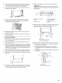
7,
Courber le tuyau de cuivre de fagon a faire un raccordement
sur I'entree du robinet quise trouve a I'arriere de la machine
glagons (voir I'illustration). Laisser un serpentin de tube en
cuivre pour permettre de sortir la machine a glagons de
I'armoire ou du mur en cas d'intervention de service•
VUE ARRII_RE
A
B
A. Tuyau de vidange (modeles avec
pompe de vidange seulement)
B. Tuyau de ventilation (medeles avec
pompe de vidange seulement)
C. Tuyau d'alimentation en eau
8=
Visser I'ecrou dans le raccord a I'extremite du tuyau en
cuivre. Serrer I'ecrou manuellement. Ensuite le serrer deux
tours de plus avec une cle. Ne pas serrer a I'exces.
REMAROUE : Pour eviter les vibrations, veiller a ce que les
tuyaux en cuivre nesoient pas en contact avec les parois
laterales de la machine a glagons ou d'autres composants
I'int@ieur de la caisse.
A B C
A.Canalisationjusqu'a
la machine a glaqons
B.Ecrou (achet_)
C.Bague (achet_e)
D E F G
D. Raccord (achet_)
E. Bague
F Ecrou
G. Canalisation fournie
provenant de la
machine a glagons
9. OUVRIR le robinet d'arr_t.
10. Verifier s'il y a des fuites. Serrer tousles raccords (y compris
les raccordements de la valve) ou les ecrous qui coulent.
Vidange par gravit_
IIfaut raccorder le tuyau de vidange de la machine a glagons
votre drain de vidange conformement aux codes et reglements
Iocaux et provinciaux. Si la machine a glagons est fournie avec
un drain de vidange par gravite, il faut suivre les instructions ci-
dessous Iors de I'installation des tuyaux de vidange. Ceci aidera
eviter que I'eau ne refoule dans le bac d'entreposage de la
machine a glagons et eventuellement sur le plancher et ne cause
des dommages.
• Les tuyaux de vidange doivent avoir au moins %" (15,88 mm)
de diametre int@ieur.
Les tuyaux de vidange doivent avoir une pente de 1" pour
chaque 48" (2,54 cm pour chaque 122 cm) de Iongueur ou
une pente de 1/4"pour chaque 12" (6,35 mm/30,48 cm) et ne
comporter aucun point bas o(_I'eau pourrait stagner.
• Les drains de vidange de plancher doivent _tre suffisamment
grands pour recevoir I'eau de vidange provenant de toutes
sources.
L'installation ideale a un tuyau de rejet a I'egout avec un
reducteur de vidange PVC de 11/2'' (3,81 cm) a 2" (5,08 cm)
installe directement sous la sortie du tuyau de vidange
comme sur I'illustration. IIfaut maintenir un ecart anti-retour
de 1" (2,54 cm) entre le tuyau de la pompe de vidange et le
tuyau de rejet a I'egout.
• II sera peut-_tre souhaitable d'isoler le tuyau de vidange
completement jusqu'a I'entree du drain de vidange.
18

VUE LATC:RALE
I
-I
I
23 _
(58,4 cm)
I
T
Y
I
2" - 1½"
(5 cm - 3,8 cm)
C
D
A. Tuyau de vidange
B. Ecart anti-retour de 1" (2,54 cm)
C. R_ducteur du drain de vidange PVC
D. Le centre du drain dewar se trouver a 23" (58,4 cm) du devant de
la porte (avec ou sans le panneau de ¾" (1,91 cm) sur la porte). Le
drain dolt aussi 6tre centre de gauche b droite (7_6" [18,56 cm] de
chaque cSt_ de la machine b glagons).
Syst_me avec pompe de vidange (sur certains modules)
Raccorder le drain de la machine & glat_ons au drain de vidange
conformement au Code international de plomberie et a tousles
codes et reglements Iocaux.
REMARQUE : Si le tuyau de vidange devient tordu et que I'eau
ne peut passe vidanger, votre machine a gla(_ons ne
fonctionnera pas.
Raccordement du conduit d'_vacuation
Apres avoir v@ifie que le systeme de vidange est adequat, il faut
preceder tel que decrit ci-dessous pour bien mettre la machine
glagons en place :
Risque du poids excessif
Utiliser deux ou plus de personnes pour deplacer et
installer la machine a glaqons.
Le non-respect de cette instruction peut causer
une blessure au dos ou d'autre blessure.
2.
Style 1 - Pour un systeme de vidange par gravite, pousser la
machine a glagons en position pour que le conduit de
vidange soit positionne au-dessus du reducteur de vidange
en PVC. Voir "Vidange par gravite" precedemment dans cette
section. Style 2 - Pour le systeme avec pompe de vidange,
connecter le tuyau de sortie de la pompe au drain. Voir
"Systeme avec pompe de vidange" precedemment dans
cette section.
3. Verifier a nouveau la machine &glagons pour s'assurer qu'elle
est bien d'aplomb. Voir la section "Nivellement".
4. Si le code sanitaire local I'exige, sceller la machine sur le
plancher a I'aide d'un produit de calfeutrage approuve une
fois que les raccordements d'eau et d'electricite ont ete faits,
...................... _....
OUTILLAGE NI_CESSAIRE :
Rassembler les outils et pieces necessaires avant de commencer
I'installation.
• Cle de %6" • Couteau a mastic plat
• Cle de 1/4" • Tournevis Phillips
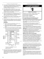
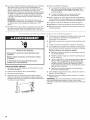
Axe de la charniere
Visde charnierea t_te hexagonale
Risque de choc electrique
Brancher sur une prise a 3 alveoles reliee a la terre.
Ne pas enlever la broche de liaison a la terre.
Ne pas utiliser un adaptateur.
Ne pas utiliser un c_ble de rallonge.
Le non-respect de ces instructions peut causer
un d_ces, un incendie ou un choc _lectrique.
1. Brancher I'appareil sur une prise a 3 alveoles reliee a la terre.
Vis de poign_e Vis d'embout
D_pose de la porte
1. Debrancher la machine a glagons ou deconnecter la source
de courant electrique.
2. Oter les vis de la poignee et la poignee (sur certains
modeles). Garder les pieces ensemble et les mettre de c6te.
3. Retirer I'axe de la charniere superieure.
4. Retirer la porte des charnieres et revisser I'axe superieur dans
la charniere superieure.
5. Inverser les embouts de porte comme suit :
• Oter les deux vis et embouts (superieurs et inf@ieurs).
• D_placer I'embout sup@ieur en diagonale sur le c6te
inf@ieur oppose, avec le c6te droit face a I'avant de la
machine a glagons.
• Deplacer I'embout inf@ieur en diagonale sur le c6te
superieur oppose, avec le c6te droit face a I'avant de la
machine a gla(_ons.
6. Mettre la porte de c6te.
19

Inversion des charni_res
1. Devisser et enlever la charniere superieure. Remettre les vis
darts les trous de charniere vides.
2. Oter les vis du bas du c6te oppose inferieur de la caisse de la
machine a glagons. Inverser la charniere superieure de telle
sorte que raxe pointe vers le haut. Placer la charniere du c6te
oppose inferieur de la machine a glagons et serrer les vis.
3. Enlever la douille de plastique de raxe de la charniere de la
"vieille" charniere inf_rieure et la replacer sur la nouvelle
charniere inferieure.
4. Oter les vis de la "vieille" charniere inferieure et la charniere.
Remettre les vis dans les trous de charniere vides.
5. Oter les vis du c6te superieur oppose de la caisse de la
machine a glagons. Inverser la charniere de telle sorte que
I'axe pointe vers le bas. Placer la charniere du c6te oppose
superieur de la machine a gla9ons et serrer les vis.
6. Oter I'axe de la charniere superieure.
R_installation de la porte
1. Placer la douille de plastique de la charniere dans le trou de la
charniere superieure sur la porte. Aligner la porte avec le trou
de la charniere superieure et reinstaller I'axe superieur.
2. Reinstaller la poignee et les vis de la poignee.
Charni_re sup_rieure
Inversion du Ioquet de porte
1. Oter les bouchons de trous du c6te oppose de la porte et les
conserver.
2. Oter les vis du Ioquet de porte magnetique et les reinstaller
du c6te oppose de la porte.
3. Pousser les bouchons de trous en place du c6te oppose de
la porte.
Risque de choc eleetrique
Brancher sur une prise a 3 alveoles reli_e a la terre.
Ne pas enlever la broche de liaison a la terre.
Ne pas utiliser un adaptateur.
Ne pas utiliser un cable de rallongeo
Le non-respect de ces instructions peut causer
un d_ees, un incendie ou un choc _lectrique.
A.Axe de la charniere
B.Douille de I'axede la charniere
C.Charniere
D. Visde charnierea t_te hexagonale
Charni_rs inf_rieure
A. Vis de charniere a t#te hexagonale
B. Douille de I'axe de la charniere
C. Chamiere
D. Axe de la charniere
4. Brancher la machine a glagons ou reconnecter la source de
courant electrique.
II est possible que votre nouvelle machine A gla(;ons emette des
bruits qui ne vous sont pas familiers. Comme ces bruits sent
nouveaux, ils peuvent vous inquieter. La plupart de ces nouveaux
bruits sont normaux. Des surfaces dures comme le plancher, les
murs et les armoires peuvent faire paraitre les bruits plus forts
qu'en realite. Les descriptions suivantes indiquent les genres de
bruits qui peuvent _tre nouveaux pour vous et leur cause.
• Vous entendrez un bourdonnement Iorsque la valve d'eau
s'ouvre pour remplir le reservoir d'eau pour chaque
programme.
• Des vibrations sonores peuvent provenir de r_coulement du
refrigerant, de la canalisation d'eau ou d'articles places sur la
machine a glagons.
• Le compresseur a haute efficacite peut produire un son aigu
ou de pulsation.
• L'eau coulant sur la plaque d'evaporation peut produire un
son d'eclaboussement.
• L'eau coulant de la plaque d'evaporation au reservoir d'eau
peut produire un son d'eclaboussement.
• A la fin de chaque programme, vous pouvez entendre un
gargouillement attribuable au refrigerant qui circule dans
votre machine a gla(;ons.
• Vous pouvez entendre de Fair qui est transmis au condenseur
par le ventilateur du condenseur.
• Au cours du programme de recolte, vous pouvez entendre un
bruit sourd Iorsque la plaque de glace glisse de I'evaporateur
sur la grille de coupe.
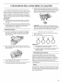
Lors de la mise en marche initiale de la machine a glat:ons, il
est possible que vous entendiez I'eau couler continuellement.
La machine a glagons est programmee pour effectuer un
programme de ringage avant de commencer a fabriquer de la
glace.
20
La page est en cours de chargement...
La page est en cours de chargement...
La page est en cours de chargement...
La page est en cours de chargement...
La page est en cours de chargement...
La page est en cours de chargement...
La page est en cours de chargement...
La page est en cours de chargement...
-
 1
1
-
 2
2
-
 3
3
-
 4
4
-
 5
5
-
 6
6
-
 7
7
-
 8
8
-
 9
9
-
 10
10
-
 11
11
-
 12
12
-
 13
13
-
 14
14
-
 15
15
-
 16
16
-
 17
17
-
 18
18
-
 19
19
-
 20
20
-
 21
21
-
 22
22
-
 23
23
-
 24
24
-
 25
25
-
 26
26
-
 27
27
-
 28
28


KitchenAid KUIC15PLTS1 Le manuel du propriétaire
- Taper
- Le manuel du propriétaire
dans d''autres langues
Documents connexes
-
KitchenAid KUIS18NNTS3 Le manuel du propriétaire
-
KitchenAid KUIO18NNVS0 Le manuel du propriétaire
-
KitchenAid KUIC15NLSS0 Le manuel du propriétaire
-
KitchenAid KUIS15NRTW4 Le manuel du propriétaire
-
-
-
-
KitchenAid KUIS18PNTW2 Le manuel du propriétaire
-
-
Autres documents
-
Whirlpool GI1500XHW6 Le manuel du propriétaire
-
-
Whirlpool GI15NFRTS1 Le manuel du propriétaire
-
Maytag JIM158XYRS0 Guide d'installation
-
Kenmore 10689482700 Le manuel du propriétaire
-
Maytag MIM1554VRB0 Le manuel du propriétaire
-
-
-
-