Lincoln Electric Ranger 305D Mode d'emploi
- Catégorie
- Système de soudage
- Taper
- Mode d'emploi

Ranger 305 D
OPERATOR’S MANUAL
IM730
August, 2004
Safety Depends on You
Lincoln arc welding and cutting
equipment is designed and built
with safety in mind. However, your
overall safety can be increased by
proper installation ... and thought-
ful operation on your part. DO
NOT INSTALL, OPERATE OR
REPAIR THIS EQUIPMENT
WITHOUT READING THIS
MANUAL AND THE SAFETY
PRECAUTIONS CONTAINED
THROUGHOUT. And, most
importantly, think before you act
and be careful.
For use with machines having Code Numbers:
10926
• Sales and Service through Subsidiaries and Distributors Worldwide •
Cleveland, Ohio 44117-1199 U.S.A. TEL: 216.481.8100 FAX: 216.486.1751 WEB SITE: www.lincolnelectric.com
• World's Leader in Welding and Cutting Products •
Copyright © 2004 Lincoln Global Inc.
This manual covers equipment which is no
longer in production by The Lincoln Electric Co.
Specications and availability of optional
features may have changed.

FOR ENGINE
powered equipment.
1.a. Turn the engine off before troubleshooting and maintenance
work unless the maintenance work requires it to be running.
____________________________________________________
1.b. Operate engines in open, well-ventilated
areas or vent the engine exhaust fumes
outdoors.
____________________________________________________
1.c. Do not add the fuel near an open flame
welding arc or when the engine is running.
Stop the engine and allow it to cool before
refueling to prevent spilled fuel from vaporiz-
ing on contact with hot engine parts and
igniting. Do not spill fuel when filling tank. If
fuel is spilled, wipe it up and do not start
engine until fumes have been eliminated.
____________________________________________________
1.d. Keep all equipment safety guards, covers and devices in
position and in good repair.Keep hands, hair, clothing and
tools away from V-belts, gears, fans and all other moving
parts when starting, operating or repairing equipment.
____________________________________________________
1.e. In some cases it may be necessary to remove safety
guards to perform required maintenance. Remove
guards only when necessary and replace them when the
maintenance requiring their removal is complete.
Always use the greatest care when working near moving
parts.
___________________________________________________
1.f. Do not put your hands near the engine fan.
Do not attempt to override the governor or
idler by pushing on the throttle control rods
while the engine is running.
___________________________________________________
1.g. To prevent accidentally starting gasoline engines while
turning the engine or welding generator during maintenance
work, disconnect the spark plug wires, distributor cap or
magneto wire as appropriate.
i
SAFETY
i
ARC WELDING CAN BE HAZARDOUS. PROTECT YOURSELF AND OTHERS FROM POSSIBLE SERIOUS INJURY OR DEATH.
KEEP CHILDREN AWAY. PACEMAKER WEARERS SHOULD CONSULT WITH THEIR DOCTOR BEFORE OPERATING.
Read and understand the following safety highlights. For additional safety information, it is strongly recommended that you
purchase a copy of “Safety in Welding & Cutting - ANSI Standard Z49.1” from the American Welding Society, P.O. Box
351040, Miami, Florida 33135 or CSA Standard W117.2-1974. A Free copy of “Arc Welding Safety” booklet E205 is available
from the Lincoln Electric Company, 22801 St. Clair Avenue, Cleveland, Ohio 44117-1199.
BE SURE THAT ALL INSTALLATION, OPERATION, MAINTENANCE AND REPAIR PROCEDURES ARE
PERFORMED ONLY BY QUALIFIED INDIVIDUALS.
WARNING
Mar ‘95
ELECTRIC AND
MAGNETIC FIELDS
may be dangerous
2.a. Electric current flowing through any conductor causes
localized Electric and Magnetic Fields (EMF). Welding
current creates EMF fields around welding cables and
welding machines
2.b. EMF fields may interfere with some pacemakers, and
welders having a pacemaker should consult their physician
before welding.
2.c. Exposure to EMF fields in welding may have other health
effects which are now not known.
2.d. All welders should use the following procedures in order to
minimize exposure to EMF fields from the welding circuit:
2.d.1.
Route the electrode and work cables together - Secure
them with tape when possible.
2.d.2. Never coil the electrode lead around your body.
2.d.3. Do not place your body between the electrode and
work cables. If the electrode cable is on your right
side, the work cable should also be on your right side.
2.d.4. Connect the work cable to the workpiece as close as
possible to the area being welded.
2.d.5. Do not work next to welding power source.
1.h. To avoid scalding, do not remove the
radiator pressure cap when the engine is
hot.
CALIFORNIA PROPOSITION 65 WARNINGS
Diesel engine exhaust and some of its constituents
are known to the State of California to cause can-
cer, birth defects, and other reproductive harm.
The engine exhaust from this product contains
chemicals known to the State of California to cause
cancer, birth defects, or other reproductive harm.
The Above For Diesel Engines
The Above For Gasoline Engines

ii
SAFETY
ii
ARC RAYS can burn.
4.a. Use a shield with the proper filter and cover
plates to protect your eyes from sparks and
the rays of the arc when welding or observing
open arc welding. Headshield and filter lens
should conform to ANSI Z87. I standards.
4.b. Use suitable clothing made from durable flame-resistant
material to protect your skin and that of your helpers from
the arc rays.
4.c. Protect other nearby personnel with suitable, non-flammable
screening and/or warn them not to watch the arc nor expose
themselves to the arc rays or to hot spatter or metal.
ELECTRIC SHOCK can
kill.
3.a. The electrode and work (or ground) circuits
are electrically “hot” when the welder is on.
Do not touch these “hot” parts with your bare
skin or wet clothing. Wear dry, hole-free
gloves to insulate hands.
3.b. Insulate yourself from work and ground using dry insulation.
Make certain the insulation is large enough to cover your full
area of physical contact with work and ground.
In addition to the normal safety precautions, if welding
must be performed under electrically hazardous
conditions (in damp locations or while wearing wet
clothing; on metal structures such as floors, gratings or
scaffolds; when in cramped positions such as sitting,
kneeling or lying, if there is a high risk of unavoidable or
accidental contact with the workpiece or ground) use
the following equipment:
• Semiautomatic DC Constant Voltage (Wire) Welder.
• DC Manual (Stick) Welder.
• AC Welder with Reduced Voltage Control.
3.c. In semiautomatic or automatic wire welding, the electrode,
electrode reel, welding head, nozzle or semiautomatic
welding gun are also electrically “hot”.
3.d. Always be sure the work cable makes a good electrical
connection with the metal being welded. The connection
should be as close as possible to the area being welded.
3.e. Ground the work or metal to be welded to a good electrical
(earth) ground.
3.f.
Maintain the electrode holder, work clamp, welding cable and
welding machine in good, safe operating condition. Replace
damaged insulation.
3.g. Never dip the electrode in water for cooling.
3.h. Never simultaneously touch electrically “hot” parts of
electrode holders connected to two welders because voltage
between the two can be the total of the open circuit voltage
of both welders.
3.i. When working above floor level, use a safety belt to protect
yourself from a fall should you get a shock.
3.j. Also see Items 6.c. and 8.
FUMES AND GASES
can be dangerous.
5.a. Welding may produce fumes and gases
hazardous to health. Avoid breathing these
fumes and gases.When welding, keep
your head out of the fume. Use enough
ventilation and/or exhaust at the arc to keep
fumes and gases away from the breathing zone. When
welding with electrodes which require special
ventilation such as stainless or hard facing (see
instructions on container or MSDS) or on lead or
cadmium plated steel and other metals or coatings
which produce highly toxic fumes, keep exposure as
low as possible and below Threshold Limit Values (TLV)
using local exhaust or mechanical ventilation. In
confined spaces or in some circumstances, outdoors, a
respirator may be required. Additional precautions are
also required when welding on galvanized steel.
5.b.
Do not weld in locations near chlorinated hydrocarbon
vapors
coming from degreasing, cleaning or spraying operations.
The heat and rays of the arc can react with solvent vapors to
form phosgene, a highly toxic gas, and other irritating pro-
ducts.
5.c. Shielding gases used for arc welding can displace air and
cause injury or death. Always use enough ventilation,
especially in confined areas, to insure breathing air is safe.
5.d. Read and understand the manufacturer’s instructions for this
equipment and the consumables to be used, including the
material safety data sheet (MSDS) and follow your
employer’s safety practices. MSDS forms are available from
your welding distributor or from the manufacturer.
5.e. Also see item 1.b.
Mar ‘95

FOR ELECTRICALLY
powered equipment.
8.a. Turn off input power using the disconnect
switch at the fuse box before working on
the equipment.
8.b. Install equipment in accordance with the U.S. National
Electrical Code, all local codes and the manufacturer’s
recommendations.
8.c. Ground the equipment in accordance with the U.S. National
Electrical Code and the manufacturer’s recommendations.
CYLINDER may explode
if damaged.
7.a. Use only compressed gas cylinders
containing the correct shielding gas for the
process used and properly operating
regulators designed for the gas and
pressure used. All hoses, fittings, etc. should be suitable for
the application and maintained in good condition.
7.b. Always keep cylinders in an upright position securely
chained to an undercarriage or fixed support.
7.c. Cylinders should be located:
• Away from areas where they may be struck or subjected to
physical damage.
• A safe distance from arc welding or cutting operations and
any other source of heat, sparks, or flame.
7.d. Never allow the electrode, electrode holder or any other
electrically “hot” parts to touch a cylinder.
7.e. Keep your head and face away from the cylinder valve outlet
when opening the cylinder valve.
7.f. Valve protection caps should always be in place and hand
tight except when the cylinder is in use or connected for
use.
7.g. Read and follow the instructions on compressed gas
cylinders, associated equipment, and CGA publication P-l,
“Precautions for Safe Handling of Compressed Gases in
Cylinders,” available from the Compressed Gas Association
1235 Jefferson Davis Highway, Arlington, VA 22202.
iii
SAFETY
iii
Mar ‘95
WELDING SPARKS can
cause fire or explosion.
6.a.
Remove fire hazards from the welding area.
If this is not possible, cover them to prevent
the welding sparks from starting a fire.
Remember that welding sparks and hot
materials from welding can easily go through small cracks
and openings to adjacent areas. Avoid welding near
hydraulic lines. Have a fire extinguisher readily available.
6.b. Where compressed gases are to be used at the job site,
special precautions should be used to prevent hazardous
situations. Refer to “Safety in Welding and Cutting” (ANSI
Standard Z49.1) and the operating information for the
equipment being used.
6.c. When not welding, make certain no part of the electrode
circuit is touching the work or ground. Accidental contact
can cause overheating and create a fire hazard.
6.d. Do not heat, cut or weld tanks, drums or containers until the
proper steps have been taken to insure that such procedures
will not cause flammable or toxic vapors from substances
inside. They can cause an explosion even
though
they have
been “cleaned”. For information, purchase “Recommended
Safe Practices for the
Preparation
for Welding and Cutting of
Containers and Piping That Have Held Hazardous
Substances”, AWS F4.1 from the American Welding Society
(see address above).
6.e. Vent hollow castings or containers before heating, cutting or
welding. They may explode.
6.f.
Sparks and spatter are thrown from the welding arc. Wear oil
free protective garments such as leather gloves, heavy shirt,
cuffless trousers, high shoes and a cap over your hair. Wear
ear plugs when welding out of position or in confined places.
Always wear safety glasses with side shields when in a
welding area.
6.g. Connect the work cable to the work as close to the welding
area as practical. Work cables connected to the building
framework or other locations away from the welding area
increase the possibility of the welding current passing
through lifting chains, crane cables or other alternate cir-
cuits. This can create fire hazards or overheat lifting chains
or cables until they fail.
6.h. Also see item 1.c.

iv
SAFETY
iv
PRÉCAUTIONS DE SÛRETÉ
Pour votre propre protection lire et observer toutes les instructions
et les précautions de sûreté specifiques qui parraissent dans ce
manuel aussi bien que les précautions de sûreté générales suiv-
antes:
Sûreté Pour Soudage A L’Arc
1. Protegez-vous contre la secousse électrique:
a. Les circuits à l’électrode et à la piéce sont sous tension
quand la machine à souder est en marche. Eviter toujours
tout contact entre les parties sous tension et la peau nue
ou les vétements mouillés. Porter des gants secs et sans
trous pour isoler les mains.
b. Faire trés attention de bien s’isoler de la masse quand on
soude dans des endroits humides, ou sur un plancher
metallique ou des grilles metalliques, principalement dans
les positions assis ou couché pour lesquelles une grande
partie du corps peut être en contact avec la masse.
c. Maintenir le porte-électrode, la pince de masse, le câble
de soudage et la machine à souder en bon et sûr état
defonctionnement.
d.Ne jamais plonger le porte-électrode dans l’eau pour le
refroidir.
e. Ne jamais toucher simultanément les parties sous tension
des porte-électrodes connectés à deux machines à souder
parce que la tension entre les deux pinces peut être le
total de la tension à vide des deux machines.
f. Si on utilise la machine à souder comme une source de
courant pour soudage semi-automatique, ces precautions
pour le porte-électrode s’applicuent aussi au pistolet de
soudage.
2. Dans le cas de travail au dessus du niveau du sol, se protéger
contre les chutes dans le cas ou on recoit un choc. Ne jamais
enrouler le câble-électrode autour de n’importe quelle partie
du corps.
3. Un coup d’arc peut être plus sévère qu’un coup de soliel,
donc:
a. Utiliser un bon masque avec un verre filtrant approprié
ainsi qu’un verre blanc afin de se protéger les yeux du ray-
onnement de l’arc et des projections quand on soude ou
quand on regarde l’arc.
b. Porter des vêtements convenables afin de protéger la
peau de soudeur et des aides contre le rayonnement de
l‘arc.
c. Protéger l’autre personnel travaillant à proximité au
soudage à l’aide d’écrans appropriés et non-inflammables.
4. Des gouttes de laitier en fusion sont émises de l’arc de
soudage. Se protéger avec des vêtements de protection libres
de l’huile, tels que les gants en cuir, chemise épaisse, pan-
talons sans revers, et chaussures montantes.
5. Toujours porter des lunettes de sécurité dans la zone de
soudage. Utiliser des lunettes avec écrans lateraux dans les
zones où l’on pique le laitier.
6. Eloigner les matériaux inflammables ou les recouvrir afin de
prévenir tout risque d’incendie dû aux étincelles.
7. Quand on ne soude pas, poser la pince à une endroit isolé de
la masse. Un court-circuit accidental peut provoquer un
échauffement et un risque d’incendie.
8. S’assurer que la masse est connectée le plus prés possible
de la zone de travail qu’il est pratique de le faire. Si on place
la masse sur la charpente de la construction ou d’autres
endroits éloignés de la zone de travail, on augmente le risque
de voir passer le courant de soudage par les chaines de lev-
age, câbles de grue, ou autres circuits. Cela peut provoquer
des risques d’incendie ou d’echauffement des chaines et des
câbles jusqu’à ce qu’ils se rompent.
9. Assurer une ventilation suffisante dans la zone de soudage.
Ceci est particuliérement important pour le soudage de tôles
galvanisées plombées, ou cadmiées ou tout autre métal qui
produit des fumeés toxiques.
10. Ne pas souder en présence de vapeurs de chlore provenant
d’opérations de dégraissage, nettoyage ou pistolage. La
chaleur ou les rayons de l’arc peuvent réagir avec les vapeurs
du solvant pour produire du phosgéne (gas fortement toxique)
ou autres produits irritants.
11. Pour obtenir de plus amples renseignements sur la sûreté,
voir le code “Code for safety in welding and cutting” CSA
Standard W 117.2-1974.
PRÉCAUTIONS DE SÛRETÉ POUR
LES MACHINES À SOUDER À
TRANSFORMATEUR ET À
REDRESSEUR
1. Relier à la terre le chassis du poste conformement au code de
l’électricité et aux recommendations du fabricant. Le dispositif
de montage ou la piece à souder doit être branché à une
bonne mise à la terre.
2. Autant que possible, I’installation et l’entretien du poste seront
effectués par un électricien qualifié.
3. Avant de faires des travaux à l’interieur de poste, la debranch-
er à l’interrupteur à la boite de fusibles.
4. Garder tous les couvercles et dispositifs de sûreté à leur
place.
Mar. ‘93

vv
Thank You
for selecting a QUALITY product by Lincoln Electric. We want you
to take pride in operating this Lincoln Electric Company product
••• as much pride as we have in bringing this product to you!
Read this Operators Manual completely before attempting to use this equipment. Save this manual and keep it
handy for quick reference. Pay particular attention to the safety instructions we have provided for your protection.
The level of seriousness to be applied to each is explained below:
WARNING
This statement appears where the information must be followed exactly to avoid serious personal injury or
loss of life.
This statement appears where the information must be followed to avoid minor personal injury or damage to
this equipment.
CAUTION
Please Examine Carton and Equipment For Damage Immediately
When this equipment is shipped, title passes to the purchaser upon receipt by the carrier. Consequently, Claims
for material damaged in shipment must be made by the purchaser against the transportation company at the
time the shipment is received.
Please record your equipment identification information below for future reference. This information can be
found on your machine nameplate.
Product _________________________________________________________________________________
Model Number ___________________________________________________________________________
Code Number or Date Code_________________________________________________________________
Serial Number____________________________________________________________________________
Date Purchased___________________________________________________________________________
Where Purchased_________________________________________________________________________
Whenever you request replacement parts or information on this equipment, always supply the information you
have recorded above. The code number is especially important when identifying the correct replacement parts.
On-Line Product Registration
- Register your machine with Lincoln Electric either via fax or over the Internet.
• For faxing: Complete the form on the back of the warranty statement included in the literature packet
accompanying this machine and fax the form per the instructions printed on it.
• For On-Line Registration: Go to our
WEB SITE at www.lincolnelectric.com. Choose “Quick Links” and then
“Product Registration”. Please complete the form and submit your registration.

vi
vi
TABLE OF CONTENTS
Page
Installation.......................................................................................................................Section A
Technical Specifications.......................................................................................................A-1
Safety Precautions ........................................................................................................A-2
Location and Ventilation................................................................................................A-2
Stacking ........................................................................................................................A-2
Angle of Operation ........................................................................................................A-2
Lifting.............................................................................................................................A-2
Additional Safety Precautions .......................................................................................A-2
High Altitude Operation .................................................................................................A-2
High Temperature Operation ........................................................................................A-2
Cold Weather Operation ...............................................................................................A-2
Towing...........................................................................................................................A-3
Pre-Operation Engine Service..............................................................................................A-3
Oil..................................................................................................................................A-3
Fuel ...............................................................................................................................A-3
Engine Coolant..............................................................................................................A-3
Battery Connections......................................................................................................A-3
Muffler Outlet Pipe ........................................................................................................A-3
Spark Arrester ...............................................................................................................A-4
Remote Control .............................................................................................................A-4
Electrical Connections..........................................................................................................A-4
Machine Grounding.......................................................................................................A-4
Welding Terminals ........................................................................................................A-4
Welding Output Cables .................................................................................................A-4
Cable Installation...........................................................................................................A-5
Auxiliary Power Receptacles and Plugs...............................................................................A-5
Standby Power Connections ................................................................................................A-5
Premises Wiring ...................................................................................................................A-6
Connection of Lincoln Electric Wire Feeders .......................................................................A-7
________________________________________________________________________________
Operation.........................................................................................................................Section B
Safety Precautions ..............................................................................................................B-1
General Description..............................................................................................................B-1
For Auxiliary Power ..............................................................................................................B-1
Engine Operation..................................................................................................................B-1
Engine Break in ...................................................................................................................B-1
Add Fuel ...............................................................................................................................B-1
Fuel ......................................................................................................................................B-1
Welder Controls ............................................................................................................B-2
Engine Controls.............................................................................................................B-3
Starting and Stopping the Engine ...........................................................................B-3, B4
Stopping .......................................................................................................................B-4
Welding Operation................................................................................................................B-5
Duty Cycle.....................................................................................................................B-5
Constant Current (Stick) Welding..................................................................................B-5
Downhill Pipe (Stick) Welding .......................................................................................B-5
Tig Welding ...................................................................................................................B-5
Typical Current Ranges for Tungsten Electrodes .........................................................B-5
Wire Welding-CV...........................................................................................................B-6
Arc Gouging ..................................................................................................................B-6
Auxiliary Power .............................................................................................................B-7
Simultaneous Welding and Auxiliary Power Loads.......................................................B-7
Extension Cord Recommendations...............................................................................B-7
________________________________________________________________________________
Accessories.....................................................................................................Section C
Field Installed Options / Accessories ...............................................................................C-1
________________________________________________________________________________

vii
TABLE OF CONTENTS
Maintenance......................................................................................................Section D
Safety Precautions ................................................................................................D-1
Routine Maintenance ............................................................................................D-1
Engine Maintenance Components ........................................................................D-1
Kubota Diesel Engine............................................................................................D-1
Engine Oil Change..........................................................................................D-2
Engine Oil Refill Capacities.............................................................................D-2
Engine Oil Filter Change.................................................................................D-2
Air Cleaner Service .........................................................................................D-2
Service Instructions And Installation Tips for Engine Air Filter .......................D-3
Cooling System .....................................................................................................D-4
Fan Belt...........................................................................................................D-4
Fuel .................................................................................................................D-4
Bleeding the Fuel System ...............................................................................D-4
Fuel Filter ........................................................................................................D-5
Engine Adjustment ..........................................................................................D-5
Battery Maintenance .......................................................................................D-5
Servicing Optional Spark Arrestor ...................................................................D-5
Welder / Generator Maintenance ........................................................................D-6
Storage ...........................................................................................................D-6
Cleaning..........................................................................................................D-6
Brush Removal and Replacement ..................................................................D-6
________________________________________________________________________
Troubleshooting..............................................................................................Section E
How to Use Troubleshooting Guide.......................................................................E-1
Troubleshooting Guide.............................................................................E-2 thru E-6
________________________________________________________________________
Diagrams and Dimension Print ......................................................................Section F
________________________________________________________________________
Parts List..................................................................................................................P417
________________________________________________________________________

RANGER 305D
1. Output rating in watts is equivalent to volt-amperes at unity power factor. Output voltage is within ± 10% at all loads up to
rated capacity. When welding, available auxiliary power will be reduced.
* Top of enclosure add 6in. (152mm) for exhaust pipe.
** Engine warranty may vary outside of the USA. (See Engine warranty for details)
A-1
INSTALLATION
A-1
TECHNICAL SPECIFICATIONS - Ranger 305D (K1727-2)
Make/Model Description Speed (RPM) Displacement Starting Capacities
cu. in. (cu. cm.) System
3 cylinder 43.88(789)
12VDC Battery &
Fuel: 12 gal.
4 stroke starter
18.8 HP High Idle 3650
Bore x Stroke inch (mm)
Oil: 3.4Qts. (3.2L)
Kubota** (14 KW)
D722 Net intermittent Full Load 3500
2.64 x 2.68
(Group 58; 550 Radiator Coolant:
3600 RPM (67 x 68 mm) cold crank amps) 3.85Qts. (3.6L)
naturally aspirated Low Idle 2450 Battery Charger
water cooled engine (3.6L)
INPUT - DIESEL ENGINE
RATED OUTPUT @ 104° F (40° C) - WELDER
HEIGHT WIDTH DEPTH WEIGHT
30.00* in. 21.50 in 52.25 in.
762.0 mm 546.0 mm 1327.0 mm
LUBRICATION EMISSIONS FUEL SYSTEM GOVERNOR
Full Pressure Electric Fuel Pump, Auto air bleed system
with Full Flow Filter Certified to EPA Tier I Electric shutoff solenoid Mechanical Governor
Indirect fuel injector
AIR CLEANER ENGINE IDLER MUFFLER ENGINE PROTECTION
Low noise Muffler: Shutdown on low oil
Single Element Automatic Idler Top outlet can be rotated. pressure & engine
Made from long life, aluminized steel. temperature
ENGINE WARRANTY: 2 year complete (parts and labor) 3rd. year major components (parts and labor)
Welding Process
DC Constant Current
DC Pipe Current
Touch-Start™TIG
DC Constant Voltage
Output Range
20 TO 305 AMPS
40 TO 300 AMPS
20 TO 250 AMPS
14 TO 29 VOLTS
Max. Weld OCV
@Rated Load RPM
60 Volts
Welding Output
Current/Voltage/Duty Cycle
305A / 29V / 100%
300A / 29V / 100%
250A / 30V / 100%
300A / 29V / 100%
Auxiliary Power
1
10,000 Watts Peak, / 9,500 Watts Continuous, 60 Hz 120/240 Volts
Sound Levels
Sound Power: 104.2 dB Lwa, Sound Level: 80.6 dBA @ 23 ft ( 7m )
PHYSICAL DIMENSIONS
ENGINE
RECEPTACLES AUXILIARY POWER CIRCUIT BREAKER OTHER CIRCUIT BREAKERS
(2) 120VAC Duplex (5-20R) Two 20AMP for Two Duplex Receptacle
25AMP for Battery Charging Circuit
(1) 120/240VAC Dual Voltage Two 50AMP for Dual Voltage
15AMP for 42V Wire Feeder Power
Full KVA (14-50R)
RATED OUTPUT @ 104° F (40° C)
.
- GENERATOR
698 lbs. (317kg.)

LIFTING
The RANGER 305D weighs approximately
775lbs.(352kg.) with a full tank of fuel. A lift bail is
mounted to the machine and should always be used
when lifting the machine.
• Lift only with equipment of ade-
quate lifting capacity.
• Be sure machine is stable when lift-
ing.
• Do not lift this machine using lift
bail if it is equipped with a heavy
accessory such as trailer or gas
cylinder.
FALLING • Do not lift machine if lift bail is
EQUIPMENT can damaged.
cause injury. • Do not operate machine while
suspended from lift bail.
--------------------------------------------------------------------------------
HIGH ALTITUDE OPERATION
At higher altitudes, output derating may be necessary. For max-
imum rating, derate the machine 2.5% to 3.5% for every 1000 ft.
(305m). Due to new EPA and other local emissions regulations,
modifications to the engine for high altitude are restricted within
the United States and some other European Countries. Use
above 6000 ft.(1828 m) may be limited due to poor engine per-
formance or excessive exhaust smoke. An authorized Kubota
engine field service shop should be contacted to determine if
any adjustments can be made for operation in higher elevations
locally.
HIGH TEMPERATURE OPERATION
At temperatures above104°F (40°C), output derating is neces-
sary. For maximum output ratings, derate the welder output 2
volts for every 50°F(10°C) above 104°F (40°C).
Cold weather starting:
With a fully charged battery and the proper weight oil,
the engine should start satisfactorily even down to
about 5°F (-15°C). If the engine must be frequently
started at or below 23°F (-5°C), it may be desirable to
install cold-starting aides. The use of No. 1D diesel
fuel is recommended in place of No. 2D at tempera-
tures below 23°F (-5°C). Allow the engine to warm up
before applying a load or switching to high idle.
Note: Extreme cold weather starting may require
longer glow plug operation.
Under no conditions should ether or other starting
fluids be used with this engine!
------------------------------------------------------------------------
WARNING
A-2
INSTALLATION
RANGER 305D
A-2
SAFETY PRECAUTIONS
Only qualified personnel should install,
use, or service this equipment.
LOCATION AND VENTILATION
The welder should be located to provide an unrestrict-
ed flow of clean, cool air to the cooling air inlets and to
avoid restricting the cooling air outlets. Also, locate the
welder so that the engine exhaust fumes are properly
vented to an outside area.
STACKING
RANGER 305D machines cannot be stacked.
ANGLE OF OPERATION
Engines are designed to run in the level condition
which is where the optimum performance is achieved.
The maximum angle of continuous operation is 20
degrees in all directions, 35 degrees Intermittent (less
than 10 minutes continuous) in all directions. If the
engine is to be operated at an angle, provisions must
be made for checking and maintaining the oil level at
the normal (FULL) oil capacity in the crankcase.
When operating the welder at an angle, the effective
fuel capacity will be slightly less than the specified 12
gallons (45ltrs.).
Do not attempt to use this equipment until you
have thoroughly read the engine manufacturer’s
manual supplied with your welder. It includes
important safety precautions, detailed engine
starting, operating and maintenance instructions,
and parts lists.
------------------------------------------------------------------------
ELECTRIC SHOCK can kill.
• Do not touch electrically live parts or
electrode with skin or wet clothing.
• Insulate yourself from work and
ground
• Always wear dry insulating gloves.
-------------------------------------------------------
ENGINE EXHAUST can kill.
• Use in open, well ventilated areas or
vent exhaust outside.
------------------------------------------------------
MOVING PARTS can injure.
• Do not operate with doors open or
guards off.
• Stop engine before servicing.
• Keep away from moving parts.
------------------------------------------------------------------------
See additional warning information at
front of this operator’s manual.
WARNING
WARNING

A-3
INSTALLATION
RANGER 305D
A-3
TOWING
The recommended trailer for use with this equipment for road,
in-plant and yard towing by a vehicle(1) is Lincoln’s K957-1. If
the user adapts a non-Lincoln trailer, he must assume responsi-
bility that the method of attachment and usage does not result
in a safety hazard nor damage the welding equipment. Some of
the factors to be considered are as follows:
1. Design capacity of trailer vs. weight of Lincoln equipment and
likely additional attachments.
2. Proper support of, and attachment to, the base of the weld-
ing equipment so there will be no undue stress to the frame-
work.
3. Proper placement of the equipment on the trailer to insure
stability side to side and front to back when being moved
and when standing by itself while being operated or ser-
viced.
4. Typical conditions of use, i.e., travel speed; roughness of sur-
face on which the trailer will be operated; environmental con-
ditions; like maintenance.
5. Conformance with federal, state and local laws.
(1)
(1) Consult applicable federal, state and local laws regarding specific requirements for use on public high-
ways.
PRE-OPERATION ENGINE SERVICE
READ the engine operating and maintenance instruc-
tions supplied with this machine.
OIL
The RANGER 305D is shipped with the engine
crankcase filled with high quality SAE 10W-30 Oil that
meets classification CG-4 or CH-4 for diesel engines.
Check the oil level before starting the engine. If it is
not up to the full mark on the dip stick, add oil as
required. Check the oil level every four hours of run-
ning time during the first 50 running hours. Refer to
the engine Operator’s Manual for specific oil recom-
mendations and break-in information.
The oil change interval is dependent on the quality of
the oil and the operating environment. Refer to the
Engine Operator’s Manual for more details on the
proper service and maintenance intervals.
FUEL
USE DIESEL FUEL ONLY
• Fill the fuel tank with clean, fresh fuel. The
capacity of the tank is 12 gals. (45.4ltrs). When
the fuel gauge reads empty the tank contains
approximately 2 gals. (7.6ltrs.) of reserve fuel.
NOTE: A fuel shut off valve is located on the pre-
filter/sediment filter. Which should be in
the closed position when the welder is not
ran for extended periods of time.
------------------------------------------------------------------------
ENGINE COOLING SYSTEM
Air to cool the engine is drawn in the base sides
and exhaust through radiator & case back. It is
important that the intake and exhaust air is not
restricted. Allow a minimum clearance of 2 feet
(0.6m) from the case back and 16in.(406mm) from
either side of the base to a vertical surface.
------------------------------------------------------------------------
BATTERY CONNECTION
Use caution as the electrolyte is a strong acid that
can burn skin and damage eyes.
------------------------------------------------------------------------
The RANGER 305D is shipped with the negative bat-
tery cable disconnected. Make certain that the RUN-
STOP switch is in the STOP position. Remove the two
screws from the rear battery tray using a screwdriver
or a 3/8" socket. Attach the negative battery cable to
the negative battery terminal and tighten using a 1/2"
socket or wrench.
NOTE: This machine is furnished with a wet charged
battery; if unused for several months, the battery may
require a booster charge. Be careful to charge the bat-
tery with the correct polarity.
MUFFLER OUTLET PIPE
Using the clamp provided secure the outlet pipe to the
outlet tube with the pipe positioned such that it will
direct the exhaust in the desired direction. Tighten
using a 9/16" socket or wrench.
CAUTION
CAUTION
WARNING
VEHICLE MOUNTING
Improperly mounted concentrated loads may
cause unstable vehicle handling and tires or other
components to fail.
• Only transport this Equipment on serviceable
vehicles which are rated and designed for such
loads.
• Distribute, balance and secure loads so vehicle
is stable under conditions of use.
• Do not exceed maximum rated loads for compo-
nents such as suspension, axles and tires.
• Mount equipment base to metal bed or frame of
vehicle.
• Follow vehicle manufacturer’s instructions.
------------------------------------------------------------------------
WARNING

A-4
INSTALLATION
RANGER 305D
A-4
SPARK ARRESTER
Some federal, state or local laws may require that
gasoline or diesel engines be equipped with exhaust
spark arresters when they are operated in certain
locations where unarrested sparks may present a fire
hazard. The standard muffler included with this welder
does not qualify as a spark arrester. When required by
local regulations, a suitable spark arrester, such as
the K1898-1 must be installed and properly main-
tained.
An incorrect spark arrestor may lead to damage to
the engine or adversely affect performance.
------------------------------------------------------------------------
REMOTE CONTROL
The RANGER 305D is equipped with a 6-pin and a
14-pin connector. The 6-pin connector is for connect-
ing the K857 or K857-1 Remote Control or for TIG
welding, the K870 foot Amptrol or the K936-2 hand
Amptrol. When in the CC-STICK, DOWNHILL PIPE,
or CV-WIRE modes and when a remote control is
connected to the 6-pin Connector, the auto-sensing
circuit automatically switches the OUTPUT control
from control at the welder to remote control.
When in TOUCH START TIG mode and when a
Amptrol is connected to the 6-Pin Connector, the
OUTPUT dial is used to set the maximum current
range of the CURRENT CONTROL of the Amptrol.
The 14-pin connector is used to directly connect a
wire feeder control cable. In the CV-WIRE mode,
when the control cable is connected to the 14-pin con-
nector, the auto-sensing circuit automatically makes
the Output Control inactive and the wire feeder volt-
age control active
NOTE: When a wire feeder with a built in welding
voltage control is connected to the 14-pin connec-
tor, do not connect anything to the 6-pin connec-
tor.
------------------------------------------------------------------------
ELECTRICAL CONNECTIONS
MACHINE GROUNDING
Because this portable engine driven welder creates its
own power, it is not necessary to connect its frame to
an earth ground, unless the machine is connected to
premises wiring (home, shop, etc.)
To prevent dangerous electric shock, other equipment
to which this engine driven welder supplies power
must be grounded to the frame of the welder using a
grounded type plug or be double insulated.
When this welder is mounted on a truck or trailer, its
frame must be electrically bonded to the metal frame
of the vehicle. Use a #8 or larger copper wire connect-
ed between the machine grounding stud and the
frame of the vehicle. When this engine driven welder
is connected to premises wiring such as that in a
home or shop, its frame must be connected to the sys-
tem earth ground. See further connection instructions
in the section entitled "Standby Power Connections"
as well as the article on grounding in the latest
National Electrical Code and the local code.
In general, if the machine is to be grounded, it should
be connected with a #8 or larger copper wire to a solid
earth ground such as a metal water pipe going into the
ground for at least ten feet and having no insulated
joints, or to the metal framework of a building which
has been effectively grounded. Do not ground the
machine to a pipe that carries explosive or com-
bustible material.
The National Electrical Code lists a number of alter-
nate means of grounding electrical equipment. A
machine grounding stud marked with the symbol
is provided on the front of the welder.
WELDING TERMINALS
The RANGER 305D is equipped with a toggle switch
for selecting "hot" welding terminal when in the "WELD
TERMINALS ON" position or "cold" welding terminal
when in the "REMOTELY CONTROLLED" position.
WELDING OUTPUT CABLES
With the engine off connect the electrode and work
cables to the output studs. The welding process dic-
tates the polarity of the electrode cable. These con-
nections should be checked periodically and tightened
with a 3/4" wrench.
Table A.1 lists recommended cable sizes and lengths
for rated current and duty cycle. Length refers to the
distance from the welder to the work and back to the
welder. Cable diameters are increased for long cable
lengths to reduce voltage drops.
WARNING
CAUTION

The 240 VAC output can be split to provide two sepa-
rate 120 VAC outputs with a max permissible current
of 44 Amps per output to two separate 120 VAC
branch circuits (these circuits cannot be paralleled).
Output voltage is within ± 10% at all loads up to rated
capacity.
The 120 V auxiliary power receptacles should only be
used with three wire grounded type plugs or
approved double insulated tools with two wire plugs.
The current rating of any plug used with the system
must be at least equal to the current capacity of the
associated receptacle.
NOTE: The 240 V receptacle has two 120 V circuits,
but are of opposite polarities and cannot be paral-
leled.
STANDBY POWER CONNECTIONS
The RANGER 305D is suitable for temporary, stand-
by or emergency power using the engine manufactur-
er’s recommended maintenance schedule.
The RANGER 305D can be permanently installed as
a standby power unit for 240 VAC, 3 wire, single
phase, 44 amp service. Connections must be made
by a licensed electrician who can determine how the
120/240 VAC power can be adapted to the particular
installation and comply with all applicable electrical
codes.
• Install the double-pole, double-throw switch
between the power company meter and the premis-
es disconnect. Switch rating must be the same or
greater than the customer’s premises disconnect
and service over current protection.
• Take necessary steps to assure load is limited to
the capacity of the RANGER 305D by installing a
50 amp, 240 VAC double pole circuit breaker.
Maximum rated load for each leg of the 240 VAC
auxiliary is 44 amperes. Loading above the rated
output will reduce output voltage below the allow-
able - 10% of rated voltage which may damage
appliances or other motor-driven equipment and
may result in overheating of the RANGER 305D
engine and/or alternator windings.
• Install a 50 amp, 120/240 VAC plug (NEMA Type
14-50) to the double-pole circuit breaker using No.
6, 4 conductor cable of the desired length. (The 50
amp, 120/240 VAC plug is available in the optional
K802R plug kit or as part number T12153-9.)
• Plug this cable into the 50 Amp, 120/240 Volt
receptacle on the RANGER 305D case front.
A-5
INSTALLATION
RANGER 305D
A-5
TABLE A-1
CABLE INSTALLATION
Install the welding cables to your RANGER 305D as
follows.
1. The diesel engine must be OFF to install welding
cables.
2. Remove the flanged nuts from the output terminals
.
3. Connect the electrode holder and work cables to the
weld output terminals. The terminals are identified
on the case front.
4. Tighten the flanged nuts securely.
5. Be certain that the metal piece you are welding (the
“work”) is properly connected to the work clamp and
cable.
6. Check and tighten the connections periodically.
• Loose connections will cause the output termi-
nals to overheat. The terminals may eventually
melt.
• Do not cross the welding cables at the output ter-
minal connection. Keep the cables isolated and
separate from one another.
------------------------------------------------------------------------
AUXILIARY POWER RECEPTACLES
The auxiliary power of the RANGER 305D consists of
two 20 Amp-120 VAC (5-20R) duplex receptacles and
one 50 Amp 120/240 VAC (14-50R) receptacle. The
240 VAC receptacle can be split for single phase 120
VAC operation.
The auxiliary power capacity is 10,500 watts Peak,
10000 Watts Continuous of 60 Hz, single phase power.
The auxiliary power capacity rating in watts is equiva-
lent to volt-amperes at unity power factor. The max
permissible current of the 240 VAC output is 44 amps.
TOTAL COMBINED LENGTH OF
ELECTRODE AND WORK CABLES
Cable Length
0-100Ft. (0-30meters)
100-150 Ft. (30-46m meters)
150-200 Ft. (46-61 meters)
Cable Size for
305 Amps
100% Duty Cycle
1 / 0 AWG
2 / 0 AWG
3 / 0 AWG
CAUTION

A-6
INSTALLATION
RANGER 305D
A-6
CONNECTION OF RANGER 305D TO PREMISES WIRING
WARNING
• Only a licensed, certified, trained electrician should install the machine to a premises or residential
electrical system. Be certain that:
• The installation complies with the National Electrical Code and all other applicable electrical codes.
• The premises is isolated and no feedback into the utility system can occur. Certain state and local
laws require the premises to be isolated before the generator is linked to the premises. Check your
state and local requirements.
• A double pole, double throw transfer switch in conjunction with the properly rated double throw
circuit breaker is connected between the generator power and the utility meter.
240 Volt
60 Hz.
3-Wire
Service
POWER
COMPANY
METER
240 VOLT
120 VOLT
120 VOLT
LOAD
N
NEUTRAL
BUS
GROUND
PREMISES
DISCONNECT AND
SERVICE
OVERCURRENT
PROTECTION
GND
N
NOTE: No. 6 COPPER CONDUCTOR CABLE SEE
NATIONAL ELECTRICAL CODE FOR ALTERNATE WIRE
SIZE RECOMMENDATIONS.
240 VOLT
GROUNDED CONDUCTOR
50AMP
240 VOLT
DOUBLE
POLE
CIRCUIT
BREAKER
DOUBLE POLE DOUBLE THROW
SWITCH RATING TO BE THE SAME
AS OR GREATER THAN PREMISES
SERVICE OVERCURRENT
PROTECTION.
50 AMP, 120/240
VOLT PLUG
NEMA TYPE 14-50
50 AMP, 120/240 VOLT
RECEPTACLE

A-7
INSTALLATION
RANGER 305D
A-7
CONNECTION OF LINCOLN ELECTRIC
WIRE FEEDERS
Connection of LN-7 or LN-8 to the RANGER 305D
• Shut the welder off.
• Connect the LN-7 or LN-8 per instructions on the
appropriate connection diagram in Section F.
• Set the "WIRE FEEDER VOLTMETER" switch to
either "+" or "-" as required by the electrode being
used.
• Set the "MODE" switch to the "CV WIRE " position.
• Set the "ARC CONTROL" knob to "0" initially and
adjust to suit.
• Set the "WELD TERMINALS" switch to the
"REMOTELY CONTROLLED" position.
• Set the "IDLE" switch to the "HIGH" position.
Connection of LN-742, Spool Gun(K487-25SG)and
Cobramatic to RANGER 305D
• Shut the welder off.
• Connect per instructions on the appropriate connec-
tion diagram in Section F.
Connection of LN-15 to the Ranger 305D
These connections instructions apply to both the LN-
15 Across-The-Arc and Control Cable models. The
LN-15 has an internal contactor and the electrode is
not energized until the gun trigger is closed. When the
gun trigger is closed the wire will begin to feed and the
welding process is started.
• Shut the welder off.
• For electrode Positive, connect the electrode cable
to the "+" terminal of the welder and work cable to
the "-" terminal of the welder. For electrode
Negative, connect the electrode cable "-" terminal of
the welder and work cable to the "+" terminal of the
welder.
• Across-The-Arc Model:
Attach the single lead from the front of the LN-15 to
work using the spring clip at the end of the lead. This
is a control lead to supply current to the wire feeder
motor; it does not carry welding current.
• Control Cable Model:
Connect Control Cable between Engine Welder and
Feeder.
• Set the MODE switch to the "CV-WIRE " position.
• Across-The-Arc Model:
Set the "WELD TERMINALS" switch to "WELD TER-
MINALS ON"
Control Cable Model:
Set the "WELD TERMINALS" switch to "REMOTELY
CONTROLLED"
• Set the "WIRE FEEDER VOLTMETER" switch to
either "+" or "-" as required by the electrode polarity
being used.
• Set the "ARC CONTROL" knob to "0" initially and
adjust to suit.
• Set the "IDLE" switch to the "High" position
Connection of an LN-23P Wire Feeder to the
RANGER 305D
• Shut the welder off.
• Connect the LN-23P as per instructions on the
appropriate connection diagram in Section F.
(NOTE): When connecting an LN-23P to the
RANGER 305D, a K350-1 adapter kit must be used.
• Set the "VOLTMETER" switch to "-".
• Set the "MODE" switch to "CV WIRE " position.
• Set the "WELD TERMINALS" switch to "REMOTELY
CONTROLLED".
• Set the "ARC CONTROL" knob to "0" initially and
adjust to suit.
• Set the "IDLE" switch to the "AUTO" position. When
not welding, the RANGER 305D engine will be at the
low idle speed. If you are using an LN-23P with the
K350-1 adapter kit, the electrode is not energized
until the gun trigger is closed. When the gun trigger
is closed, the current sensing circuit will cause the
RANGER 305D engine to go to the high idle speed,
the wire will begin to feed and the welding process
can be started. When welding is stopped, the engine
will revert to low idle speed after approximately 12
seconds unless welding is resumed.

A-8
INSTALLATION
RANGER 305D
A-8
Connection of PRINCE XL SPOOL GUN to the
Ranger 305D
Connection of the Prince XL Spool Gun requires the
use of the K1849-1 Adapter Module.
• Shut the Welder off.
• For electrode Positive, connect the electrode cable
to the "+" terminal of the welder and work cable to
the "-" terminal of the welder. For electrode
Negative, connect the electrode cable "-" terminal of
the welder and work cable to the "+" terminal of the
welder.
• Connect the Control Cable of the Spool Gun to the
Adapter Module and connect the Control Cable of
the Adapter Module to the Welder.
• Connect the Gas Hose.
• Set the MODE switch to the "CV-WIRE " position.
• Set the "WELD TERMINALS" switch to "WELD
TERMINALS ON".
• Set the "ARC CONTROL" knob to "0" initially and
adjust to suit.
• Set the “IDLE” switch to the “HIGH” position.
Connection of the LN-25 to the RANGER 305D
Shut off welder before making any electrical con-
nections.
------------------------------------------------------------------------
The LN-25 with or without an internal contactor may
be used with the RANGER 305D. See the appropriate
connection diagram in Section F.
NOTE: The LN-25 (K431) Remote Control Module
and (K432) Remote Cable are not recommended for
use with the RANGER 305D.
1. Shut the welder off.
2. For electrode Positive, connect the electrode
cable from the LN-25 to the "+" terminal of the
welder and work cable to the "-" terminal of the
welder. For electrode Negative, connect the elec-
trode cable from the LN-25 to the "-" terminal of
the welder and work cable to the "+" terminal of
the welder.
3. Attach the single lead from the front of the LN-25
to work using the spring clip at the end of the lead.
This is a control lead to supply current to the wire
feeder motor; it does not carry welding current.
4. Set the MODE switch to the "CV-WIRE " position.
5. Set the "WELD TERMINALS" switch to "WELD
TERMINALS ON"
6. Set the "ARC CONTROL" knob to "0" initially and
adjust to suit.
7. Set the "IDLE" switch to the "AUTO" position.
When not welding, the RANGER 305D engine will
be at the low idle speed. If you are using an LN-25
with an internal contactor, the electrode is not
energized until the gun trigger is closed.
8. When the gun trigger is closed, the current sens-
ing circuit will cause the RANGER 305D engine to
go to the high idle speed, the wire will begin to
feed and the welding process started. When weld-
ing is stopped, the engine will revert to low idle
speed after approximately 12 seconds unless
welding is resumed.
If you are using an LN-25 without an internal con-
tactor, the electrode will be energized when the
Ranger 305D is started.
------------------------------------------------------------------------
WARNING
CAUTION

B-1
OPERATION
RANGER 305D
B-1
SAFETY PRECAUTIONS
Do not attempt to use this equipment until you have
thoroughly read the engine manufacturer’s manual sup-
plied with your welder. It includes important safety pre-
cautions, detailed engine starting, operating and main-
tenance instructions, and parts lists.
------------------------------------------------------------------------
ELECTRIC SHOCK can kill.
• Do not touch electrically live parts or
electrode with skin or wet clothing.
• Insulate yourself from work and ground
• Always wear dry insulating gloves.
• Always operate the welder with the hinged door closed
and the side panels in place.
• Read carefully the Safety Precautions page before
operating this machine. Always follow these and any
other safety procedures included in this manual and in
the Engine Instruction Manual.
GENERAL DESCRIPTION
The RANGER 305D is a diesel engine powered DC multi-
process welding power source and 120 / 240 volt AC power
generator. The engine drives a generator that supplies three
phase power for the DC welding circuit and single phase
power for the AC auxiliary outlets. The DC welding control
system uses state of the art Chopper Technology (CT tm)
for superior welding performance.
FOR AUXILIARY POWER:
Start the engine and set the IDLER control switch to the
desired operating mode. Full power is available regardless
of the welding control settings providing no welding current
is being drawn.
The auxiliary power of the RANGER 305D consists of two
20 Amp-120 VAC (5-20R) duplex receptacles and one 50
Amp 120/240 VAC (14-50R) receptacle. The 240 VAC
receptacle can be split for single phase 120 VAC operation.
ENGINE OPERATION
Before Starting the Engine:
• Be sure the machine is on a level surface.
• Open top & side engine doors and remove the engine oil
dipstick and wipe it with a clean cloth. Reinsert the dip-
stick and check the level on the dipstick.
• Add oil (if necessary) to bring the level up to the full mark.
Do not overfill. Close engine door.
• Check radiator for proper coolant level. (Fill if necessary).
• See Engine Owner’s Manual for specific oil and coolant
recommendations.
ADD FUEL
• Remove the fuel tank cap.
• Fill the tank approximately 4 inches (100mm) from the top
of the filler neck to allow for fuel expansion (observe the
fuel gauge while filling). DO NOT FILL THE TANK TO THE
POINT OF OVERFLOW.
• Replace the fuel cap and tighten securely.
• See Engine Owner’s Manual for specific fuel recommenda-
tions.
BREAK-IN PERIOD
Lincoln Electric selects high quality, heavy-duty industrial
engines for the portable welding machines we offer. While it is
normal to see a small amount of crankcase oil consumption
during initial operation, excessive oil use, wetstacking (oil or tar
like substance at the exhaust port), or excessive smoke is not
normal.
Larger machines with a capacity of 350 amperes and higher,
which are operated at low or no-load conditions for extended
periods of time are especially susceptible to the conditions
described above. To accomplish successful engine break-in,
most diesel-powered equipment needs only to be run at a rea-
sonably heavy load within the rating of the welder for some
period of time during the engine’s early life. However, if the
welder is subjected to extensive light loading, occasional mod-
erate to heavy loading of the engine may sometimes be neces-
sary. Caution must be observed in correctly loading a
diesel/generator unit.
1. Connect the welder output studs to a suitable resistive load
bank. Note that any attempt to short the output studs by
connecting the welding leads together, direct shorting of the
output studs, or connecting the output leads to a length of
steel will result in catastrophic damage to the generator and
voids the warranty.
2. Set the welder controls for an output current and voltage
within the welder rating and duty cycle. Note that any
attempt to exceed the welder rating or duty cycle for any
period of time will result in catastrophic damage to the gen-
erator and voids the warranty.
3. Periodically shut off the engine and check the crankcase oil
level.
WARNING
• Stop engine while fueling.
• Do not smoke when fueling.
• Keep sparks and flame away
from tank.
• Do not leave unattended while
fueling.
• Wipe up spilled fuel and allow
fumes to clear before starting
engine.
• Do not overfill tank, fuel
expansion may cause overflow.
DIESEL FUEL ONLY
-----------------------------------------------------------------------
WARNING
DIESEL FUEL
can cause fire.

B-2
OPERATION
B-2
WELDING CONTROLS (Figure B.1)
1. OUTPUT CONTROL:
The OUTPUT dial is
used to preset the output voltage or current as dis-
played on the digital meters for the four welding
modes. When in the CC-STICK, DOWNHILL PIPE or
CV-WIRE modes and when a remote control is con-
nected to the 6-Pin or 14-Pin Connector, the auto-
sensing circuit automatically switches the OUTPUT
CONTROL from control at the welder to the remote
control.
In the CV-WIRE mode, when the wire feeder control
cable is connected to the 14-Pin Connector, the auto-
sensing circuit automatically makes OUTPUT CON-
TROL inactive and the wire feeder voltage control
active.
When in the TOUCH START TIG mode and when a
Amptrol is connected to the 6-Pin Connector, the
OUTPUT dial is used to set the maximum current
range of the CURRENT CONTROL of the Amptrol.
2. DIGITAL OUTPUT METERS
The digital meters allow the output voltage (CV-WIRE
mode) or current (CC-STICK, PIPE and TIG modes)
to be set prior to welding using the OUTPUT control
dial. During welding, the meter display the actual out-
put voltage (VOLTS) and current (AMPS). A memory
feature holds the display of both meters on for seven
seconds after welding is stopped. This allows the
operator to read the actual current and voltage just
prior to when welding was ceased.
While the display is being held the left-most decimal
point in each display will be flashing. The accuracy of
the meters is +/- 3%.
3. WELD MODE SELECTOR SWITCH:
(Provides four selectable welding modes)
CV-WIRE
DOWNHILL PIPE
CC-STICK
TOUCH START TIG
RANGER 305D
1
10
7
4
9
5
8
11
12
13
6
15
14
17
16
2
3
FIGURE B.1

B-3
OPERATION
B-3
4. ARC CONTROL:
The ARC CONTROL dial is
active in the CV-WIRE, CC-STICK and DOWNHILL PIPE
modes, and has different functions in these modes. This
control is not active in the TIG mode.
CC-STICK mode: In this mode, the ARC CONTROL dial
sets the short circuit current (arc-force) during stick welding
to adjust for a soft or crisp arc. Increasing the dial from –10
(soft) to +10 (crisp) increases the short circuit current and
prevents sticking of the electrode to the plate while welding.
This can also increase spatter. It is recommended that the
ARC CONTROL be set to the minimum number without
electrode sticking. Start with a setting at 0.
DOWNHILL PIPE mode: In this mode, the ARC CONTROL
dial sets the short circuit current (arc-force) during stick
welding to adjust for a soft or a more forceful digging arc
(crisp). Increasing the number from –10 (soft) to +10 (crisp)
increases the short circuit current which results in a more
forceful digging arc. Typically a forceful digging arc is pre-
ferred for root and hot passes. A softer arc is preferred for
fill and cap passes where weld puddle control and deposi-
tion ("stacking" of iron) are key to fast travel speeds. It is
recommended that the ARC CONTROL be set initially at 0.
CV-WIRE mode: In this mode, turning the ARC CONTROL
clock wise from –10 (soft) to +10 (crisp) changes the arc
from soft and washed-in to crisp and narrow
. It acts as an
inductance/pinch control. The proper setting depends
on the procedure and operator preference. Start with
a setting of 0.
5. WELD OUTPUT TERMINALS WITH
FLANGE NUT: Provides a connection point for the
electrode and work cables.
6. GROUND STUD: (graphic)
Provides a connection point for connecting the
machine case to earth ground.
7. 14-PIN CONNECTOR: For attaching wire
feeder control cables to the RANGER 305D. Includes
contactor closure circuit, auto-sensing remote control
circuit, and 120V and 42V power. The remote control
circuit operates the same as the 6 Pin Amphenol.
8. 6-PIN CONNECTOR: For attaching optional
remote control equipment. Includes auto-sensing
remote control circuit.
9. WELD TERMINALS CONTROL SWITCH:
In
the WELD TERMINALS ON position, the output is
electrically hot all the time. In the REMOTELY CON-
TROLLED position, the output is controlled by a wire
feeder or amptrol device, and is electrically off until a
remote switch is depressed.
10. WIRE FEEDER VOLTMETER SWITCH:
Matches the polarity of the wire feeder voltmeter to
the polarity of the electrode.
ENGINE CONTROLS: (Figure B.2)
FIGURE B.2
11. RUN/STOP SWITCH - RUN position ener-
gizes the engine prior to starting. STOP position stops
the engine. The oil pressure interlock switch prevents
battery drain if the switch is left in the RUN position
and the engine is not operating.
12. GLOW PLUG PUSH BUTTON -
When pushed activates the glow plugs as well as the
electric fuel pump for quick starting. Glow plug should
not be activated for more then 20 seconds continu-
ously.
AUTO BLEED FUNCTION – Air will automatically
bleed from the fuel system by simply pushing the
GLOW PLUG BUTTON. It is generally not required
to crack open fittings in the fuel system to bleed air
from the fuel system.
13. START PUSH BUTTON -
Energizes the starter motor to crank
the engine.
14. IDLER SWITCH- Has two positions as follows:
1) In the HIGH position, the engine runs at the high
idle speed controlled by the engine governor.
2) In the AUTO position, the idler operates as follows:
• When switched from HIGH to AUTO or after start-
ing the engine, the engine will operate at full speed
for approximately 12 seconds and then go to low
idle speed.
• When the electrode touches the work or power is
drawn for lights or tools (approximately 100 Watts
minimum), the engine accelerates and operates at
full speed.
• When welding ceases or the AC power load is
turned off, a fixed time delay of approximately 12
seconds starts. If the welding or AC power load is
not restarted before the end of the time delay, the
idler reduces the engine speed to low idle speed.
• The engine will automatically return to high idle
speed when there is welding load or AC power
load reapplied.
RANGER 305D

B-4
OPERATION
B-4
15. ENGINE ALTERNATOR TROUBLE
LIGHT-The engine alternator light is off when battery
charging system is functioning normally. If light turns
on, the alternator or the voltage regulator may not be
operating correctly. The light may also come on due
to the battery not holding a charge. It is normal for the
light to be on while initially starting the engine.
16. ENGINE HOUR METER – Displays the total
time that the engine has been running. This meter is
useful for scheduling prescribed maintenance.
17. ENGINE PROTECTION LIGHT-A warning
indicator light for Low Oil Pressure and/or Coolant
Over Temperature. The light is off when the systems
are functioning properly. The light turns on when the
RUN-STOP switch is in the “ON” position prior to
starting the engine. If the Engine Protection or Battery
Charging Lights do “not” turn off shortly after starting
the engine shut off the engine immediately and deter-
mine the cause.
STARTING THE ENGINE
1. Remove all plugs connected to the AC power
receptacles.
2. Set IDLER switch to AUTO.
3. Set the RUN/STOP switch to RUN.
4. Press Glow Plug Button and hold 5 to 10 seconds.
5. Press and hold both the “Glow Plug” Button and
START button together until the engine starts or for
up to 10 seconds.
6. Release the engine START button immediately
when the engine starts.
7. Release the glow plug button after the Engine
Protection Light turns off or after an additional 5
seconds maximum.
8. The engine will run at high idle speed for approxi-
mately 12 seconds and then drop to low idle speed.
Allow the engine to warm up at low idle for several
minutes before applying a load and/or switching to
high idle. Allow a longer warm up time in cold
weather.
NOTE: If the unit fails to start repeat step 4 through
step 7 after waiting 30 seconds
• Do not allow the starter motor to run continuously
for more than 20 seconds.
• Do not push the START button while the engine
is running because this can damage the ring
gear and/or the starter motor.
• IF the Engine Protection or Battery Charging
Lights do “not” turn off shortly after starting the
engine shut off the engine immediately and deter
mine the cause.
-----------------------------------------------------------------------
NOTE: When starting a RANGER 305D for the first
time, or after and extended period of time of not oper-
ating, it will take longer than normal because the fuel
pump has to fill the fuel system.
STOPPING THE ENGINE
Remove all welding and auxiliary power loads and
allow the engine to run at low idle speed for a few
minutes to cool the engine.
STOP the engine by placing the RUN-STOP switch in
the STOP position.
NOTE: A fuel shut off valve is located on the fuel pre-
filter.
RANGER 305D
CAUTION
TYPICAL RANGER 305D FUEL CONSUMPTION
Kubota D722 Running time for
Gal./Hr (Liters/Hr) 12 gallons-hours
Low Idle - No Load
2450 R.P.M. .29 (1.09) 41.77
High Idle - No Load
3650 R.P.M. .54 (2.06) 22.02
DC Weld Output
250 Amps @ 28 Volts 1.03 (3.91) 11.62
DC Weld Output
300 Amps @ 29 Volts 1.18 (4.47) 10.16
10,000 Watts 1.16 (4.38) 10.37
7,000 Watts .96 (3.63) 12.50
3,000 Watts .70 (2.67) 17.03
TABLE B.1
La page charge ...
La page charge ...
La page charge ...
La page charge ...
La page charge ...
La page charge ...
La page charge ...
La page charge ...
La page charge ...
La page charge ...
La page charge ...
La page charge ...
La page charge ...
La page charge ...
La page charge ...
La page charge ...
La page charge ...
La page charge ...
La page charge ...
La page charge ...
La page charge ...
La page charge ...
La page charge ...
La page charge ...
La page charge ...
La page charge ...
La page charge ...
La page charge ...
La page charge ...
La page charge ...
La page charge ...
La page charge ...
La page charge ...
La page charge ...
-
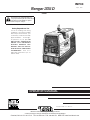 1
1
-
 2
2
-
 3
3
-
 4
4
-
 5
5
-
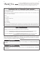 6
6
-
 7
7
-
 8
8
-
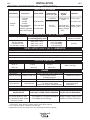 9
9
-
 10
10
-
 11
11
-
 12
12
-
 13
13
-
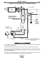 14
14
-
 15
15
-
 16
16
-
 17
17
-
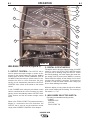 18
18
-
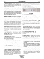 19
19
-
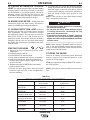 20
20
-
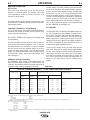 21
21
-
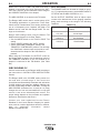 22
22
-
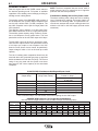 23
23
-
 24
24
-
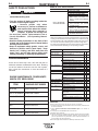 25
25
-
 26
26
-
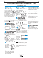 27
27
-
 28
28
-
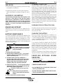 29
29
-
 30
30
-
 31
31
-
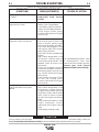 32
32
-
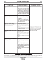 33
33
-
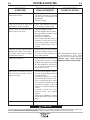 34
34
-
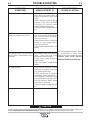 35
35
-
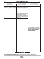 36
36
-
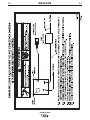 37
37
-
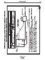 38
38
-
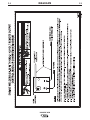 39
39
-
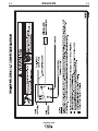 40
40
-
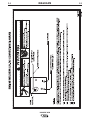 41
41
-
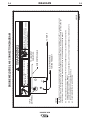 42
42
-
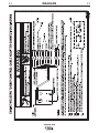 43
43
-
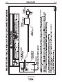 44
44
-
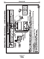 45
45
-
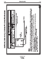 46
46
-
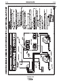 47
47
-
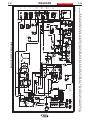 48
48
-
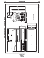 49
49
-
 50
50
-
 51
51
-
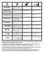 52
52
-
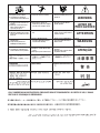 53
53
-
 54
54


Lincoln Electric Ranger 305D Mode d'emploi
- Catégorie
- Système de soudage
- Taper
- Mode d'emploi
dans d''autres langues
Documents connexes
-
Lincoln Electric Ranger 305D Mode d'emploi
-
Lincoln Electric SA-250 Mode d'emploi
-
-
-
-
-
Lincoln Electric LN-25 Pro Mode d'emploi
-
-
-