
WORKSHOP MANUAL
MANUEL D’ATELIER
WERKSTAT TANLEITUNG
DIESEL ENGINES
MOTEUR
DIESELMOTOREN
DIESEL
68mm STROKE SERIES
MOTEUR
DE
68mm
DE
COURSE
SERIENMOTORMIT 68mm HUB


I
TO
THE
READER
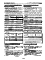
This Workshop Manual has
been
prepared
to
provide servicing personnel
with
information on
the
mechanism, service and maintenance of KUBOTA Diesel
Engine
68
mm
STROKE
SERIES.
It
is
divided into
two
parts, "Mechanism" and
"Disassembling and Servicing".
Mechanism
Information on construction and functions are included for each engine
section. This part should be understood before proceeding with trouble-
shooting, disassembling and servicing.
H
Disassembling and Servicing
Under the heading "General" come general precautions, troubleshooting,
lists
of servicing specifications and periodic inspection items. For each engine
section, there are
If
Checking and Adjustment",
"
Disassembling and Assembling",
and "Servicing" which cover procedures, precautions, factory specification and
allowable
Ii
mits.
All the engines that have been menufactured since January of
1994
are clean
exhaust engines.
The mark
[E]
in
the
WSM refers to
the
said clean engine.
All information, illustrations and specifications contained in
this
manual are
based on the latest production information available at
the
time
of
publication.
The
right
is
reserved to make changes
in
all
information
at
any time without
notice.
July
'90
@
KUBOTA
Corporation
1990
INTRODUCTION
Ce manuel d'atelier
a
et6
prepare pour permettre au personnel d'entretien de
disposer d'informations sur
les
mbcanisrnes, les entretiens
et
la maintenance des
moteurs Kubota Diesel moteur de serie
?I
68
mm de course.
II
est divise en deux
sections: "M6canismes"
et
If
DCmontage
et
entretien".
MBcanisme
Des informations sur la construction
et
les fonctions sont donnees pour
chaque partie du moteur. Cette partie du manuel doit &re comprise avant que
I'oncommence
les
operations de recherche des anomalies, de dernontage et
d'entretien.
H
DBrnontage et entretien
Sous
le
titre "GenCralitCs" on trouvera des precautions g4n6ralesI
les
procedures de recherche des anomalies et
les
listes de caracteristiques
d'entretien et items de verification periodique. Pour chaque partie du moteur,
on trouvera fes
titres
"Verification
et
reglage",
If
DBmontage et remontage"
et
If
Entretien"
013
sont reprises
les
precautions,
les
caracteristiques d'usine
et
les
limite de service.
Les moteurs fabriques depuis Janvier
1994
ont et6 congus de facon
a
produire
d'bchappement non polluants.
Ces moteurs non polluants sont indiquCs dans
le
manual d'atelier par
la
lettre
[El.
Toutes lees informations, illustrations et specifications contenues dans ce
manuel sont basees sur les dernieres informations de production disponibles au
moment de la publication. Nous nous reservons le droit de modifier tout
element de ces infomations,
a
tout moment et sans preavis.
Juillet
'90
@
KUBOTA Corporation
1990

FUR
DEN
LESER
Dieses Handbuch sol1 dem Wartungspersonanl lnformationen uber die
Funktion, den Betrieb und die Wartung der KUBOTA-Dieselmotoren
Serienmotormit
68
mm Hub liefern.
Es
ist
in zwei
Teile,
"Funktion" und "Ausbau
und Wartung" aufgegliedert.
Mechanismus'
Fur jeden Motorabschnitt werden lnformationen bezuglich Konstruktion und
Funktion gegeben. Dieser
Teil
sollte sorgfaltig gelesen werden, bevor mit der
Storungssuche, dem Ausbau und der Wartung begonnen wird.
H
Ausbau
und
Wartung
Der Abschnitt "allgemeines" beinhaltet allgemeine Vorkehrungen, Storungs-
suchen und Listen von Wartungsdaten sowie von regelmaBig zu uberprufenden
Tellen. Fur jeden Motorabschnitt
ist
ein Kapitel "Prufung und Einstellung",
"Aus- und Einbau" und "Wartung" vorgesehen, welches Uber Verfahrensweisen,
Vorkehrungen, Werkdaten und zulassige Grenzwerte AufschluB gibt.
Alle Motoren, die ab Januar
1994
hergestellten werden sind Sauberab-
Motoren.
Die Marke [E] bezieht sich auf den vorgenannten sauberen Motor.
Allen in diesem Hanbuch enthaltenen Informationen, Abbildungen und
technischen Merkmalen liegen die letzten, zum Zeitpunkt der Veroffentlichung
verfugbaren lnformationen zugrunde. Eine Anderung aller lnformationen zu
jeder
Zeit
und ohne Ankundigung bleibt vorbehalten.
Juli
'90
@
KUBOTA
Copration
1990
I

CONTENTS
SPECIFICATIONS
I
PERFORMANCE CURVES
4
DIMENSIONS
6
M.
MECHANISM
F. FEATURE
M-I
1.
ENGINE BODY M-3
[I]
CYLINDER BLOCK M-3
[2] CYLINDER HEAD M-3
[31
CRANKSHAFT
M-5
[4] PISTON AND PISTON RINGS
-*---*----*-*-----*
M
-5
151
CONNECTING
ROD
M-5
[6]
CAMSHAFT M-7
[8] ROCKER
ARM
M-7
[9] VALVE TIMING
......................................
M-7
2. LUBRICATING SYSTEM M-9
[I] GENERAL
M-9
[2] OIL PUMP M-11
131
RELIEF
VALVE
M-11
[4]
OIL
FILTER
CARTRIDGE
M-11
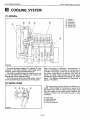
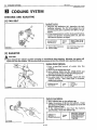
3. COOLING SYSTEM
M-I
5
[I]
GENERAL M-15
..................................
....................................
.......................................
.................................
............................................
[71
FLYWHEEL
..............................................
M-7
........................................
...............................................
............................................
......................................
.........................
[51
OIL
PRESSURE
SWITCH
.........................
M-13
.............................................
......................................
[2] WATER PUMP M-15
131
THERMOSTAT
M-17
141
RADIATOR
M-17
151
RADIATOR
CAP
M-17
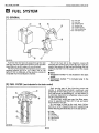
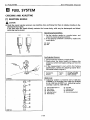
4.
FUEL SYSTEM
M-I
9
[I]
GENERAL M-19
[2] FUEL FILTER M-19
131
FUEL
FEED
PUMP
M-2
1
141
~NJECT~ON PUMP
M-2
1
151
INJECTION NOZZLE
M-27
[6]
GOVERNOR M-27
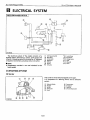
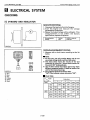
5. ELECTRICAL SYSTEM M-31
......................................
...........................................
....................................
.............................................
.........................................
.................................
.................................
...............................
.........................................
11
1
STARTING
SYSTEM
...............................
M-31
[2] CHARGING SYSTEM
.............................
.M-39
S.
DISASSEMBLING AND SERVICING
G. GENERAL
s-I
DISASSEMBLING AND ASSEMBLING
...........
S-113
[l]
ENGINE IDENTIFICATION
........................
s-
1
S-113
[2] GENERAL PRECAIJTlONS
.........................
s-
1
[I]
OIL PUMP S-113
[4]
TROUBLESHOOT~NG
S-8
CHECKING AND ADJUSTING 5-117
[5] SERVICING SPECIFICATIONS
..................
5-1 6
[I]
FAN BELT S-117
[6] MAINTENANCE CHECK LIST
..................
5-32 [2] RADIATOR S-117
[7] CHECK AND MAINTENANCE
.................
s-35 [31
THERMOSTAT
5-1 19
[a]
SPECIAL TOOLS
.....................................
5-49 DISASSEMBLING AND ASSEMBLING
...........
5-1 19
s-57
[l]
THERMOSTAT AND WATERPUMP
.......
5-1 19
CHECKING AND ADJUSTING
........................
5-57
4.
FUEL SYSTEM
s-I
21
DISASSEMBLING AND ASSEMBLING
............
5-61 CHECKING AND ADJUSTING
......................
5-121
[l]
DRAINING WATER AND
OIL
..................
5-6 1
[I]
INJECTION NOZZLE
............................
s-121
[2] EXTERNAL COMPORNENTS
..................
5-6 1 [2] INJECTION PUMP
................................
S-123
SE
RV
IC1
N G
................................................
...........................................
131
TIGHTENING
TORQUES
...........................
5-5 3. COOLING SYSTEM S-117
...............................
.......................
............................................
..........................................
......................................
1.
ENGINE BODY
~
[3] CYLINDER HEAD AND VALVES
c...........
..
5-61 DISASSEMBLING AND ASSEMBLING
------*----
S-127
141 TIMING
GEAR
AND CAMSHAFT.........
.....
5-67
[I]
INJECTION NOZZLE
.............................
~
S-127
~
[5] PISTON AND CONNECTING ROD
............
5-73 S-129
[6] FLYWHEEL AND CRANKSHAFT
..............
5-79 CHECKING 5-129
SERVICING
...................................................
S-83
[l]
CYLINDER HEAD AND VALVES
...............
5-83 [2] STARTER S-131
[2] PISTON AND CONNECTING ROD
............
5-93 131
GLOW
PLUG
S-131
[3]
TIMING GEAR AND CAMSHAFT.--.----.----- 5-97 DISASSEMBLING AND ASSEMBLING
..........
S-133
141
CRANKSHA
FT..-.-.........-.....-....-..-...-.-.-
S-103
[I]
STARTER 5-133
151
CYLINDER
...........................................
5-1
11
SERVICING 5-135
2.
LUBRICATING SYSTEM
5-113
[I]
SIARTER
............................................
S-135
CHECKING
................................................
S-113
5.
ELECTRICAL SYSTEM
.................................................
[l]
DYNAMO AND REGULATAR
................
S-129
.............................................
........................................
.............................................
................................................
rn
(il
l
I
a

TABLE
DES
CARACTERISTI Q U
ES
2
COURBES DE PERFORMANCE
4
DIMENSIONS 6
MATI
E R
ES
M.
MECANISME
F.
GENERALITES M-2
I.
CORPS DU MOTEUR
M-4
[I] BLOC-MOTEUR M-4
[2] CUMSSE M-4
[3] VlLEBREQUlN M-6
141
PISTON
ET
SEGMENTS
M-6
[5] BlELLE M-6
[6] ARBRE
A
CAMES M-8
[71
VOLANT
M-8
[a]
CULBUTEURS M-8
2. SYSTEME DE LUBRIFICATION M-9
[I]
GENEMLITES M-9
[2] POMPE
A
HUlLE M-12
[3] SOUPAPE DE DECHARGE
.....................
M-12
141
CARTOUCHE DE FILTREA HUlLE
**---*-=.-
M-12
[5] MANOCONTACT DE PRESSION
D'HUILE M-14
......................................
................................................
........................................
...........................
...................................................
....................................
................................................
........................................
[9] CALAGE DE DISTRIBUTION
....................
M-8
........................................
...................................
...............................................
3.
SYSTEME DE REFROIDISSEMENT M-16
[I]
GENERALITES M-16
121 POMPE A EAU
M-I
6
[3] THERMOSTAT M-18
[41
RAD~ATEUR
M-18
[5] BOUCHON DU RADIATEUR
*---.--.-*---.*-.*
M-18
4.
SYSTEME D'ALIMENTATION M-20
[I]
GENERALlTES M-20
[2] FlLTRE A CARBURANT M-20
[3] POMPE D'ALIMENTATION DE
COMBUSTlBLE M-22
241
POMPE
D'INJECTION
M-22
[51
~NJECTEURS
M-28
[6] REGUMTEUR M-28
5.
SYSTEME ELECTRIQUE M-32
111 SYSTEME DE DEMARRAGE
-.-****---*-..--**
M-32
[2] CIRCUIT DE CHARGE
............................
M-40
......................................
.....................................
.....................................
.........................................
.......................................
..........................
......................................
...........................
........................................
......................................
S.
DEMONTAGE ET ENTRETIEN
G. GENERALITES s-2
[l]
IDENTIFICATION DU MOTEUR
**--.---.--****--
s-2
[2] PRECAUTIONS GENERALITES
--..*--.---.*--*--
5-2
[3] COUPLES DE
SERWGE
S-6
141
DEPANNAGE
s-10
[5] CARACTERISTIQUES D'ENTRETIEN
---.-*..
5-22
[6] LISTE DES VERIFICATION
D'ENTRETIEN 5-33
[7] VERIFICATION ET ENTRETIEN
*..-.-..*---.--
S-36
[e]
OUTlLS SPEClAUX S-50
S-58
VERlFlCATlON ET
REGUGE
S-58
DEMONTAGE ET MONTAGE S-62
[l]
VIDANGE D'EAU ET D'HUILE
~**-*.*..*..**---
5-62
[31
CULASSE
ET
SOUPAPES
S-62
CAMES S-68
............................
.........................................
........................................
.................................
1
I
CORPS DU MOTEUR
........................
.......................
[2] COMPOSANTES EXTERNES
...................
5-62
.........................
[4]
PIGNON DE DISTRIBUTION ETARBRE A
...................................................
.................................
[51
PISTON
ET
B~ELLE
s-74
[6] VOLANT ET VILEBREQUIN
.....................
S-80
[2] PISTON ET BlELLE 5-94
..................................................
ENTRETlEN S-84
[I]
CULASSE ETSOUPAPES
..........................S-84
..................................
[3] PIGNON DE DISTRIBUTION
ETARBRE
A
WMES
5-98
[4]
VlLEBREQUlN S-104
[51
CYL~NDRE
s-111
.................................
.....................................
...........................................
2. SYSTEME DE LUBRlFlCATlON
S-114
V
E
R1
F
I
CAT1
0
N
S-114
DEMONTAGE
ET
MONTAGE 5-1 14
ENTRETlEN S-114
[I]
POMPEA HUlLE S-114
3. SYSTEME DE REFROIDISSEMENT
S-I18
VERIFICATION ET REGMGE S-118
[l]
COURROIE DE VENTILATEUR
******-*..-*--
S-118
[2] WDlATEUR S-118
[31
THERMOSTAT
5-120
DEMONTAGE ET MONTAGE s-120
[l]
THERMOSTAT ET POMPE
A
EAU
.........
5120
4.
SYSTEME D'ALIMENTATION s-I22
VERlFlCATlON ET REGLAGE s-122
[I]
INJECTEUR s-122
[2] POMPE D'INJECTION S-124
DEMONTAGE ET MONTAGE s-128
[I]
INJECTEUR
S-I
28
5.
SYSTEME ELECTRIQUE S.130
VERlFlCATlON 5-130
[I]
ALTERNATEUR ET REGULATEUR..---.*-*- S-130
[2] DEMARREUR S-132
[3] BOUGIE DE PRECHAUFFAGE
**.****.***-..-*
S-132
DEMONTAGE ET MONTAGE S-134
[I]
DEMARREUR
.......................................
S-134
ENTRETlEN 5-136
...........................................
.......................
...............................................
..................................
......................
.........................................
......................................
.....................
......................
...........................................
.............................
.....................
.........................................
...........................................
.......................................
......................
................................................
[I]
DEMARREUR
.......................................
S-136

TECHNISCHE MERKMALE
3
LEISTU NGSKU RVEN
4
ABMESSUNGEN
6
M.
MECHANISMUS
F.
ALLGEMEINES
M-2
I.
MOTORKORPER
M-4
[I]
ZYLlNDERBLOCK M-4
[2] ZYLlNDERKOPF M-4
[3~
KURBELWELLE
M-6
[51
PLEUELSTANGE
M-6
[6] NOCKENWELLE M-8
171
SCHWUNGRAD
M-8
[a] KlPPHEBEL M-8
[9] VENTILSTEUERUNG
...............................
M-8
2.
SCH MlERU NGSSYSTEM
M-9
[I]
ALLGEMElNES M-9
[2] OLPUMPE M-12
[3]
~BERDRUCKVENT~L
M-12
[4] OLFILTERPATRONE M-1 2
[5] OLDRUCKSCHALTER M-14
...................................
.....................................
......................................
[4] KOLBEN UND KOLBENRINGE
..................
M-6
.....................................
.....................................
......................................
.............................................
.......................................
............................................
............................
..............................
............................
M-16
M-16
[2] WASSERPUMPE M-16
[3] THERMOSTAT M-18
[4]
K~HLER
M-18
[51
KISHLERVERSCHLUSSKAPPE
M-18
4.
KRAFTSTOFFSYSTEM M-20
[I]
ALLGEMlNES
M-20
[2] KRAFTSTOFFFlLTER M-20
[4] ElNSPRlTZPUMPE M-22
[5]
E~NSPR~TZDUSE
M-28
[6] DREHZAHLREGLER M-28
5.
ELEKTRISCHESSYSTEM M-32
[2] LADESYSTEM M-40
3.
K~HLUNGSSYSTEM
[I]
ALLGEMElNES
.....................................
...................................
.....................................
...............................................
................
.......................................
.............................
[3]
KRAFTSTOFF.F~RDERPUMPE
................
M-22
................................
...................................
..............................
[l]
ANLABERSYSTEM
...............................
M-32
......................................
S.
AUSBAU UND WARTUNG
G.
ALLGEMEINES
s-2
[
11 MOTOR KENNZEICHNUNG
.....................
5-2
[2] ALLGEMEINE VORKEHRUNGEN
.............
5-2
[31
ANZUGSDREHMOMENTE
5-7
[6] WARTUNGS-CHECKLISTE 5-34
.......................
.................................
[4] STORUNGSSUCHE 5-13
[5] WARTUNGSDATEN 5-27
[7] UBERPRUFUNG UND WARTUNG
-.-.-------
5-36
[a] SPEZIALWERKZEUGE 5-50
I.
MOTORKORPER
S-58
OBERPRUFUNG UND EINSTELLUNG
--.----------
S-58
AUSBAU UND ElNBAU 5-62
[1] ABLASSEN VON WASSER UND
bL--------
5-62
[2] AUssERE BAUTElLE 5-62
...............................
......................
............................
.................................
..............................
[3] ZYLINDERKOPF UND VENTILE
..............
5-62
[4] STEUERUNG UND NOCKENWELLE........
.
5-68
[SI KOLBEN UND PLEUELSTANGE
-*-.----------
5-74
[l]
ZYLINDERKOPF UND VENTILE
...............
5-84
[2] KOLBEN UND PLEUELSTANGE
................
5-94
151
ZYL~NDER
5-1 12
[6] SCHWUNGRAD UND KURBELWELLE
-.---
5-80
WARTUNG 5-84
..................................................
[3] STEUERUNG UND NOCKENWELLE---------. 5-98
[4] KURBELWELLE 5-1 04
S-114
UBERPR~FUNG
5-1 14
....................................
............................................
2.
SCHMl ERU NGSSY STEM
.........................................
..
I
AUSBAU UND ElNBAU
.................................
5-1 14
WARTUNG S-114
[I]
OLPUMPE
5-1
14
S-I
18
OBERPRUFUNG UND EINSTELLUNG...
.........
5-1
18
[I]
L~FTERR~EMEN
5-1
18
5-1
18
[2]
K~HLER
131
THERMOSTAT
5-120
AUSBAU UND ElNBAU s-120
[I]
THERMOSTAT UND WASSERPUMPE
....
5-120
4.
KRAFTSTOFFSYSTEM S-122
UBERPRUFUNG UND EINSTELLUNG
..........
5-122
[I]
EINSPRITZDOSE
s-122
................................................
...........................................
3.
KO
H
LU
NGSSYSTEM
..................................
..............................................
......................................
...............................
...................................
[2] ElNSPRlTZPUMPE
..................................
5-124
AUSBAU UND ElNBAU S-128
[I]
ElNSPRlTZDUSE 5-128
5.
ELEKTRISCHESSYSTEM S-130
...............................
..................................
UBERPR~FUNG
.........................................
5-130
UND
REGLER
.........................................
S-130
111
WECHSELSTROM-LICHTMASCHINE
...........................................
[2]
ANLASSER 5-132
[3]
GL~HKERZE 5-1
32
AUSBAU UND ElNBAU 5-134
[I]
ANLASSER 5-134
WARTU NG 5-136
[I]
ANLASSER 5-136
........................................
...............................
...........................................
................................................
...........................................

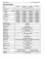
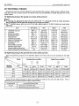
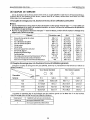
SPEC1
FI
CAT1
0
NS
68 mm STROKE
SERIES
WSM,
01
165
Model
Type
S
P
ECI
Fl
CAT1
0
N
5
2442-8
(E)
I
2482-8
(E)
I
0662-8
(E)
I
0722-8
(E)
Vertical, liquid cooled, 4-cycle diesel engine
2
67
x
68 (2.64
x
2.68)
Number
of
Cylinders
I
2
3
3
64
x
68 (2.52
x
2.68)
67
x
68 (2.64
x
2.68)
Total Displacement
CC
(cu. in.)
Cont. H.P. 10.0 HPB600 rDm
479 (29.23)
8.1 kWI3600 rpm
10.8 HP/3600 rpm
9.3 kW13600 rpm
12.5 HP13600 rpm
10.4
kW/3600 rpm
13.9 HPL3600 rDm
~
656 (40.05) 7 I9 (43.89)
11.2 kWI3600 rpm
15.0 HPB600 rpm
12.9 kWL3600 rpm
17.3 HPB600 rpm
14.3 kWB600 rpm
19.2 HP/3600 rDm
12.2 kWL3600 rpm
16.3 HPB600 rpm
14.0 kWB600 rpm
18.8 HPB600 rpm
15.6 kWB600 rpm
20.9 HPB600 rDm
V
L
,$
SAE Net 8.6 kWB600 rpm
Intermittent H.P.
I I
.5
HPB600 rpm
SAEGross 9.5 kWB600 rprn
intermittent H.P. 12.7 HPn600 ram
1
7.4 kWB600 rpm
10.0 PSB600 rprn
Y
e
7.9 kWI3600 rpm
I
11.0 kW/3600 rpm
1
12.1 kW13600 rpm
10.8 PSB600 rprn 15.0 PSB600 rpm
16.4 PSB600 rpm
I
8.2 kWB600 rpm 8.9 kWB600 rpm
12.3 kW/3600 rpm 13.3 kWB600 rpm
I
I
.I PSB600 rprn 12.1 PSB600 rpm 16.7 PSI3600 rpm
18.1 PSB600 rpm
8.9 kWB600 rpm 9.7 kWB600 rpm
13.5 kWL3600 rpm 14.6 kWB600 rpm
12.1 PSn600 rDm 13.2 PSI3600 rDm
18.3 PSB600 rDm 19.9 PS/3600 rDm
DIN6271-NB
DIN 70020
MaximumBare Speed
Minimum Bare Idling Speed
Combustion Chamber
3800 rpm
9OOto
1000 rpm
Spherical type
Fuel lnjezon Pump
Governor
Direction of Rotation
lniection Nozzle
Bosch MD mini Pump
Centrifugal
Ball
Mechanical Governor
Counter-clockwise (viewed from flywheel)
Bosch Throttle Type
injection Timing
injection Order
Injection Pressure
0.35 to 0.38 rad. (20’to 229 before T.D.C.
1-2
I
1-2
I
1-2-3
I
1-2-3
13.73 MPa (140 kgflcmz, 1991 psi)
~~~ ~ ~ ~~
Compression Ratio
Lubricatinq System
23:l
Forced Lubrication by Pump
I
Diesel Fuel
No.2-D
(ASTM D975)
I
Fuel
I
Oil
Pressure Indication
Lubricating Filter
Cooling system
Starting System
Electrical Type Switch
Full Flow Paper Filter (Cartridge Type)
Pressurized Radiator (not included in the basic model), Forced Circulation with Water Pump
Electric Starting With Cell Starter
12V. 0.8 kW
1
~
Starting Support Device
~ ~~~ ~
by
Glow Plug in Combustion Chamber
Battery
Generator for Charging
12V, 35AH, equivalent
12V,150W
~~
Lubricating Oil
Lubricating Oil Capacity
Weight (Dry)
Application
~-
API Service CD or
CE
2.1
P
(2.2 U.S.qts., 1.85 Imp. qts)
2.5
P
(2.6 U.S.qts., 2.21 Imp. qts)
53.1 kg (1 17.1 Ibs)
I
53.1 kg (117.1 Ibs)
3.21(3.4 U.S.qts.,2.81 Imp.qts)
3.8P(4.0 U.S.qts.,3.31 1rnp.qts)
63.7 kg (140.4 Ibs)
I
63.1 kg (139.1 Ibs)
General Power Sourcc

68mm STROKESERIES VSPJ,01165
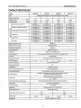
CARACTERlSTlQU
ES
CARACTERISTIQUES
Z442-B
(E)
2482-8
(E)
I
Vlodele
D662-8
(E)
D722-B
(E)
I
rvDe
IyIindr6e totale (cm3)
I
43
7
I
479
I
656
I
71 9
I
Moteur diesel
B
4tem~s,vertical et
8
refroidissement par liquide
~
Uombre de cylindres
Msagexcourse
(mm)
2 2
3
3
64
x
68
67
x
68 64x68 67 x 68
DIN 6271-NA
Puisance continue
SAE,
net
I
7,4 kWB600 tr/mn
7,9 kW/3600 tr/mn
10,O CVB600 tr/mn.
I
10.8 CVB600 tr/mn
7,5 kWB600 trlmn 8.1 kWB6OOtr/mn
10.0
HPB600 tr/mn 10.8 HPB600 tr/mn
Puissance intermittente SAE, net
Puisance intermittente SAE, brut
I
11,2 kWB600 trhn 12,2 kWB600 trlmn
15,0HPB600tr/mn
I
16.3 HPB600tdmn
8,6 kWB600 tr/mn 9,3 kWB600 tdrnn
11,5HPB600tr/mn 12,5 HPB600tr/mn
9,5 kWB600tr/mn 10,4 kWB60Otr/mn
12.7 HPB600 tr/mn 13.9 HPB600 tr/mn
12,9 kWB600tr/mn
17,3 HPB600 tr/mn
DIN 6271-NB
DIN 70020
14,3 kWB600 tr/mn
19,2 HPB600 tr/mn
11
,O
kWn'600 tr/mn
15,O CVB600 tr/mn
8.2 kWB600 tr/mn 8,9 kWB600 tr/mn
1 1,l CVB600 tr/mn 12.1 CVB600 tr/mn
8.9 kWB600 tr/mn 9,7 kWB600 trlmn
12,l CV/3600tr/mn 13,2 CVB600tr/mn
18,8 HPB600tr/mn
RBgime maximum
B
vide
Regime minimum
B
vide
Cham bre de corn bustion
15,6 kWl3600 tr/mn
12,l kWL3600tr/mn
16,4 CVi3600 tr/mn
3800tdmn
900
B
1000 tr/mn
Sphbrique
~~
RBgu lateur
Sens de rotation
lniecteurs
I
Bosch MDType Mini
Pompe d'injection
I
~
MBcanique centrifuge
B
bille
En sens inverse des aiguilles d'une montre (vue du c6t6 volant)
Typ
Bosch
B
jet
Calage de I'injection
Ordre d'injection
Pression d'injection
0,35
B
0.38 rad.
(20"B
22") avant P.M.H,
1-2
I
1-2
I
1-2-3
I
1-2-3
13,73 MPa (140 kgf/cm2)
Taux de compression
I
23:l
I
___~
Lubrification
Indication de pression d'huile
Filtre de lubrification
Forcee, par pompe
Par contact electrique
Filtre
B
element en papier (type
B
cartouche)
~~
Refroidissement
Ddmarrage
Dispositif auxiliaire au demarrage
Alternateur
Radiateur sous pression (non compris dans le moteur de base),
circulation forcee avec pompe
8
eau
Dbmarrage electrique avec dbmarreur
12V, 0,8 kW
Par bougie de prechauffage, dans la chambre de combusion
12V. 35AH.,ou equivalent
~~ ~
Circuit de charge
Carburant
2
12 V, 150 W
Carburant diesel
No
2-D (ASTM D975)
-
~ ~~~
Huile de lubrification--
Capacit6 en huile de lubrification
Poids
(A
sec)
ADDlhtiOn
API Service CD ou CE
2,l
P
3,2
Q
2,5
P
3.8
Q
53.1 kg
I
53,l kg 63,7 kg
I
63,l kg
Source de puissance tout usage

TECHNISCHE
MERKMALE
68
rnrn
STROKE
SERIES
WSM,
01
I
65
2482-B
(E)
D662-B
(E)
TECHNISCHE
MERKMALE
D722-B
(E)
~~~
Zylinderzahl
Bohrung x Hub
(rnrn)
I
TVD
I
Vertikal, wasseraekiihlter Viertakt-Dieselmotor
I
~
._
~
2
2
3
64
x
68 67
x
68 64 x 68
I
Hubrauminhalt (cm3)
SAE Netto-PS kontinuierlich
+
67 x 68
43
7
479 656
719
7.5 kW/3600 UlMin 8,l kWi3600 U/Min 11,2 kW/3600 U/Min 12,2 kW/3600 UlMin
10.0
HPl3600 UlMin 10.8 HPB600 UlMin
15.0 HP13600 UlMin 16.3 HPl3600 UlMin
8,6 kW/3600 UlMin
11,5 HP/3600 U/Min
SAE Netto-PS intermittierend
SAE Brutto-PS intermittierend
E!
9,3 kWi3600 UlMin
12,5 HPB600 UlMin
12,9 kWi3600 UlMin
17,3 HPi3600 UlMin
&i
I
DIN6271-NA
9,5 kWB600 U/Min
12,7 HPn600 UlMin
7,4 kWB600 U/Min
10.0 PSB600 UlMin
10.4 kWB600 UlMin
13,9 HPB600 UlMin
7,9 kWB600 U/Min
10,8 Psi3600 UlMin
14,3 kW/3600 UlMin
19,2 HPl3600 UlMin
11.0
kW/3600 UlMin
15,O PSB600 UlMin
1-
8,9 kWB600 U/Min
12,l PSl3600 UlMin
DIN 70020
I
18,8 HPB600 UlMin
9,7 kWi3600 UlMin 13,5 kWi3600 UlMin 14,6 kW/3600 UlMin
73,2 PSB600 UlMin 18,3 PSl3600 UlMin 19,9 PSB60D UlMin
15'6 kW/3600 UlMin
16,4 Psi3600 UlMin
Max imaldrehzahl
Minimal-Leerlaufdrehza hl
Verbrennungskarnmer
I
8,2 kWB600 UlMin
8,9 kWi3600 UlMin 12,3 kWl3600 UlMin 13,3 kWi3600 U/Min
I
11.1
PSB600 U/Min
I
12,l Psi3600 U/Min
I
16,7 P93600 UlMin
I
18,l PSB600 UlMin
3800 UlMin
900 bis
1000 U/Min
Kugelformig
Drehzahlregler
Drehrichtung
Einspritzdiise
Einspritzta kt
Mechanischer Fliehkraft Kugelregler
Entgegen dem Uhrzeigersinn (von der Schwungradseite aus gesehen)
Bosch mit Drosselklappe
0,35 bis 0,38 rad. (20' bis 22') vor
O.T.
I
Kraftstoff-Einspritzpumpe
I
8osch MD Typ Mini
1
~~
Einspritzdruck
VerdichtunqsverhBltnis
~-
13,73 MPa (140 kplcm2)
23:
1
I
Einspritzfolge
dldruckanzetge
SchmierungsBlfilter
Kiihlunqssvstem
I
1-2
I
1
-2
I
1-2-3
I
1-23
I
Elektrischer Schalter
VollfluB-Papierfilter (Patronentyp)
Druckkuhier (Nicht irn Basismotor enthalten) Zwangsurnlauf mit Wasserpumpe
AnlaRsystern
AnlaR-Unterstiitzunnsvorrichtunq
I
Schrnierungssystern
I
Druckschrnierung durch Getriebepurnpe
I
Elektrisch mit Zellenanlasser
l2V, 0,8kW
Durch Gluhkerze irn Verbrennungskamrner
Batterie
Lichtrnaschine fur Ladung
Kraftstoff
12V, 35AH, gleichwertig
12V,150W
Diesel-Kraftstoff Nr. 2-D (ASTM D975)
SchmierungsBI
SchmierungsBlmenge
Gewicht (trocken)
Anwendung
API-Service CD bzw
CE
2,l
P
3,2
P
2,5
P
3,8
P
53,l kg
I
53,l kg 63,7 kg 63,l kg
Allgerneine Antriebsqucll
3

68
mm
STROKE
SERIES
VJSM,
01
164
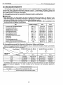
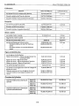
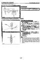
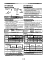
PERFORMANCE
CURVES/
COURBES
DE
PERFORMANCE/ LEISTUNGSKURVEN
PERFORMANCE
COURBES
DE
LEISTUNGSKURVEN
CURVES
PERFORMANCE
I
2442-B
(E)
A1 1
HP
0
Z482-6
(E)
A1 16F003
13-
FE
62
12-
Y
11-
ps
10
09
8-
e
m
210
190
116 18
zb
22 2'4 26
28
30 32
3h
i6
rpmX1OO
@
A1 16F004
(1)
Brake Horsepower (1) Puissance au frein
(2) Engine Speed
(2)
Vitesse de rnoteur
(3)
B.S.F.C.
(3)
B.S.F.C.
(4)
Torque
(4)
Couple
(5)
Gross Intermittent Torque
(5)
Couple intermittent brut
(6)
Net Intermittent Toraue (6) Couple intermittent net
(1)
Bremspferdekraft
(2)
Motorendrehzahl
(3)
B.S.F.C.
(4)
Drehkraft
(5)
GesarntesAussetzdrehmoment
(6) Netto Aussetzdrehmornent
..
(7)
Net Cont. Torque
(8)
Grosslntermittent B.H.P. (8) Puissance au frein intermittent brut
(9)
Net Intermittent B.H.P.
(9)
Puissance au frein intermittent net
(7) Couple continu net
(7)
Netto Dauerdrehmoment
(8)
Gesarnte aussetzende Bremspferdekraft
(9)
Netto aussetzende Bremspferdekraft
(10)
Net Cont
B.H.P.
(1
1)
BS.F-C(Net Intermittent)
(10)
Puissance au frein continue net (10) Netto Dauer-Bremspferdekraft
(1
1)
tonsommation de carburantspgcifique
pour
wai
de moteur sur le banc d'esai
desfreins
(B51.C)
(intermittent net)
(1
1) Spezificher Treibstoffverbrauch der
Bremse (B5F.C) (netto aussetzend)
4

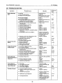
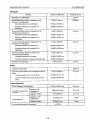
PERFORMANCE CURVES
/
COU
RBES
DE PERFORMANCE
/
LEISTUNGSKURVEN
68 mm
STROKE
SERIES
WSM.
01 164
.32
.28
.2 4
I
D662-B(E)
D722-B
(E)
20
18.
16
HP
0.J
14.
12.
10
8.
+E
mm
2.L
2-v
?
m
-10)
0.45 200
HP
0
20
18.
16.
14.
12.
10.
8
6-
I
I-
2
m
-I
?
2
m
0.45
2
v
A109F006
20-
18.
16.
PS
0.J
14‘
12.
10~
8.
6-
c
mi
Y
5
B
200
m
(1)
Brake Horsepower (1) Puissance au frein
(2)
Engine Speed
(2)
Vitesse de moteur
(3) B.S.F.C. (3)
B.S.F.C.
(4) Torque (4) Couple
(5) Gross intermittent Torque (5) Couple intermittent brut
(6) Net Intermittent Torque (6) Couple intermittent net
(7)
Net Cont. Toraue
(7)
Couple continu net
(1) Bremspferdekraft
(2) Motorendrehzahl
(3)
B.S.F.C.
(4)
Drehkraft
(5)
GesamtesAussetzdrehmoment
(6) Netto Aussetzdrehmoment
(7)
Netto Dauerdrehmoment
(8) Gross Intermittent B.H.P.
(9) Net intermittent B.H.P.
(9)
Puissance au frein Intermittent net (9) Netto aussetzende Bremspferdekraft
(1
0)
Netto Dauer-Brernspferdekraft
(1 1) Spezifischer Treibstoffverbrauch der
8remse (B.S.F.C.) (netto aussetzend)
(8)
Puisiance au frein intermittent brut
(8)
GesamteaussetzendeBremspferdekraft
(IO) Net Cont. B.H.P.
(1 1)
B.S.F.C.
(Net Intermittent)
(10) Puissance au frein continue net
(1 1) Consommation de carburant specifique
pour
essai de moteur sur le banc d‘essai
des freins (B.S.F.C.) (intermittent net)
5

68
mm
STROKE
SERIES
WSM,01164
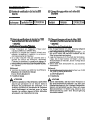
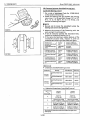
DIMENSIONS
f
DIMENSIONS
f
ABMESSUNGEN
DIMENSIONS
DIMENSIONS
ABMESSUNGEN
'
2442-B
(E),
2482-B
(E)
389(15.31)
376.504.82)
178(7.01) 198.5(7.81)
!
1
16F009
I
D662-B
(E),
D722-B
(E)
376.504.82
Unit, Unite,
Einheit:
rnm
(in.]
351U4.32)
A116F010
426.2(16.78)
83.1(15.08)
/25m
3,
A1
16F011
A1
16M09
6

DIMENSIONS/ DIMENSIONS/ABMESSUNGEN
68
mm
STROKE
SERIES
WSM,
01
164
2442-8
(E),
Z482-B
(E)
D662-B
(E),
D722-8
(E)
Unit, Unit& Einheit: mm (in.)
A: 16 dia.
(0.63
dia.)
B:
25.4 dia.
(1
.OO
dia.)
C:
12 (0.47)
D:
8(0.31)
A116F021
A1
16F022
7

M.
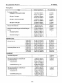
MECHANISM
MECANISME
MECHANISMUS

M.F
FEATURE
68
mm
STROKE
SERIES
WSM,OI
165
I
0109FOll
FEATURE
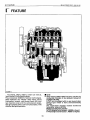
The Z442-B, Z482-B, D662-B,
D722-B
are vertical,
liquid-cooled,
4-cycle
diesel engines.
They incorporate
KUBOTA's
foremost technologies.
With KUBOTA's the
"NTVCS"
(New Three Vortex
Combustion System), well-known Basch MD mini
type injection pump and the well-balanced design,
they give greater power,
low
fuel consumption,
little
vibration and quiet operation.
NOTE
0
Since January
1994,
E-NCS
has been used for the
combustion chamber of our products instead of
traditional N-TVCS.
E-TVCS
was developed with an eye toward clean
exhaust gas which
is
more environmentally
friendly.
The
combustion chamber models mentioned
hereinafter refers to
E-WCS.
Model
of
combustion chamber
:
N-TVCS (Engine Serial Number
;
489290
or lower)
E-TVCS
(Engine Serial Number
;
489291
or higher)
M-l

68mrnSTROKESERIES
WSM,07165
M-F
GENERALiTES/ALLGEMEINES
GENERALITES
ALLGEMEINES
W
0109F012
Les moteurs Z442-B, 2482-8, D662-B D722-B sont
des moteurs diesel
a
4 temps,
A
cylindres veritcaux
et
refroidissement par liquide.
Ils
incorporent
les
technoligies les plus avancees KUBOTA. Le "NTVCS"
(nouveau systerne de combustion
a
trois vortex)
KUBOTA, les fameuses pompes d'injection MD mini,
et une conception bien equilibree donnent
a
ces
moteurs une puissnace accrue, une consommation
tr&s
basse, un faible niveau de vibrations et un
fonctionnement silencieux.
H
NOTA
0
La charnbre d'explosion, auparavant rnodele N-
TVCS, des appareils produits depuis Janvier
1994
a
&e rernplacee par le rnodkle E-TVCS, plus
Bcologique et produisant
des
gaz d'echappernent
rnoins polluants.
Le rnodele des charnbres d'explosion suivantes
sera indique par
E-TVCS.
Modele de
la
charnbre d'explosion
:
N-TVCS (NurnBro de sprie
du
rnoteur
;
anterieur
E-TVCS
(NurnBro de sprie du rnoteur
;
posterieur
5
489290)
5
489291)
Bei
den Motoren Z442-B, Z482-B, D662-B, D722-B
handelt
es
sich
um
verti kale, wassergeekuhlte,
Viertakt-Dieselmotoren. Sie sind nach der neuesten
Technologie KUBOTAS ausgelegt. Das
"
NTVCS"
(neues
Dreiwirbel-Verbrennungssystem
KUBOTA, der
bekannten Einspritzpumpe Typ MD mini von Bosch
und der durchdachten, ausgewogenen Konstruktion
bieten
sie
hohere Leistung, geringen
Kraftstoffvrebrauch sowie vi brationsarmen und
ruhigen Lauf.
H
ANMERKUNG
e
In
allen ab
1.
Januar
1994
produzierten Anlagen
wurde der bisherige Brennkarnrnertyp N-TVCS
durch den neu entwickelten T
p
E-TVCS ersetzt,
der dank reinerer Abruft besonders
urnweltfreundlich ist.
Die folgenden Beschreibungen beziehen
sich
auf
den Brennkarnrnertype
E-TVCS.
Brennkarnrnertyp
:
N-TVCS (Motorseriennurnrnern
489290
und davor)
E-WCS
(Motorseriennurnrnern
489291
und
danach)
M-2

M.l
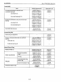
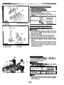
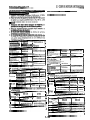
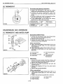
ENGINE BODY
68 mm
STROKE
SERIES
WSM,
01
160
a
ENGINE
BODY
[I]
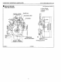
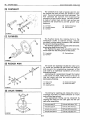
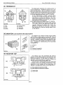
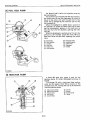
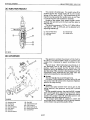
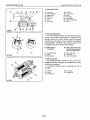
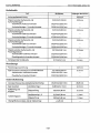
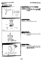
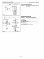
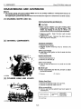
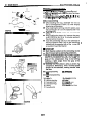
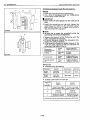
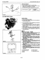
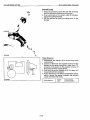
CYLINDER BLOCK
[2]
CYLINDER HEAD
11 09F014
29
3087F009
60
D087F010
The engine has
a
high durability tunnel-type
cylinder block
in
which
the
crank bearing component
is
a
constructed body. Furthermore, liner
less
type,
allow effective cooling,
less
distortion, and greater
wear-resistance.
The noise
level
is
reduced to
a
minimum because each cylinder has
its
own chamber.
The cross-flow type intake/exhaust ports
in
this
engine have their openings
at
both sides of the
cylinder head. Because overlaps of intake/exhaust
ports are smaller
than
in
ports of other types which
have openings on one side, the suction air
can
be
protected from being heated and expanded by
heated exhaust air.
The
cool, high density suction air
has high volume efficiency and raises the power of
the
engine. Furthermore, distortion of the cylinder
head by heated exhaust gas
is
reduced because
intake ports are arranged alternately.
The
combustion chamber
is
of KUBOTA's exclusive New
TVCS
combustion chamber type, Suction air
is
whirled
to
be mixed effectively with fuel, prompting
combustion and reducing fuel consumption.
In
the combustion chamber are installed throttle
type injection nozzle and rapid heating sheathed
type glow plug.
This glow plug assures easier than
ever engine
starts
even at
-15°C
(5°F).
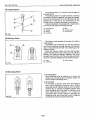
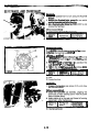
(1)
Combustion Chamber
(2)
Intake Port
(3)
Exhaust Port
(4) Nozzle Assembly
(5)
Glow
Plug
(6) Cylinder Head
(7) Fan-shaped Concave
(8)
Stream
(9)
Air Inlet
Combustion System
These
engine use the "NTVCS" (New Three Vortex
Combustion System) to achieve perfect combustion
for maximum power. The
NTVCS
combustion system
provides unique shape of throat
in
the
air inlet
(9)
for
combustion chamber, to produce three streams
(8)
of
air
in
the
chamber
(1)
when compressing, giving
an
ideal mixture
of
air and fuel.
In addition,
a
fan-shaped concave
(7)
is
provided
on top of
the
piston to allow
a
smooth ejection of
the
exhaust gas, offering highly efficient
com bustion.
M-3

68
rnrn
STROKE
SERIES
WSM,
0
I
160
M-1
CORPS
DU
MOTEUR/MOTOR
KORPER
CORPS
DU
MOTEUR
MOTORKORPER
[I]
BLOC-MOTEUR
Le moteur
est
dote d'un palier de type tunnel, avec
le logement des paliers de vilebrequin faisant corps.
De plus,
les
sans chemises, assurent un
refroidissement efficace, reduisent les risquent de
deformation, et favorisent une meilleure resistance 8
I'usure;
en
outre, le fait que chaque cylindre est dot6
de
sa
propre chambre contribue au silence de
fonctionnement du moteur.
[2]
CULASSE
Ce
moteur est dote d'une culasse 8 flux trans-
versant, dont
les
lumi6res d'admission/echappement
sont placees de part
et
d'autre.
Par suite du fait que
le
chevauchement des lumieres admission/
echappement est moindre que dans les autres types
de moteur 8 lumieres placees du m@me c6t6,
I
air
aspire peut @tre protege du rkchauffement et de
I'expansion causes par la proximiti, des gaz
d'echappement chauds.
L'air frais, aspire 8 haute
densite, possede un rendement volumetriqque
&levee,
ce
qui augmente la puissance du moteur. De
plus,
les
risques de deformation de la culasse
provoquee par les gaz dechappement brQlants sont
moindres, Btant donne que les chapelles d'admission
se trouvent de I'autre
c6tC.
La chambre de
combustion est de type Nouveau TVCS, une
exclusivite KUBOTA. L'air aspire est mis en
turbulance,
ce
ui donne un melange efficace avec le
consom mati on.
Dans
la
chambre de combustion
se
trouvent les
injecteur
3
jet et
les
bougies de prechauffage.
Ces
bougies ameliorent le demarrage 8 des temperatures
pouvant descendre jusqu'8 -15°C.
(1)
Chambrede combustion
(6)
Culasse
(2)
Lumikre d'admission
(7)
Surface concave en
(3)
Lurnikre d'echappement Bventail
(4)
Ensem ble injecteur
(8)
Trois courants
(5)
Bougie de prBchauffage
(9)
Admission d'air
carburant, am6
9
iorant la combustion
et
reduisant la
I
System
de
Combustion
Le moteur utilise le "NTVCS" (nouveau systeme de
combustion
B
trois vortex) permettant une
combustion parfaite pour obtenir la puissance
maximum. Le systeme de combustion NTVCS
presente une forme unique d'btranglement dans
I'entrCe d'air
(9)
pour la chambre de combustion
pour produire trois courants d'air
(8)
dans
la
chambre
(11)
lors de la compression, assurant
un
melange
optimum d'air et de carburant. De
Ius, une surface
pour permettre une ejection rCguliere de gar
d'echappement, offrant une efficacite de
combustion
tr&
Olevee.
concave en Cventail(7) est prevue
S
P
a tGte
du
piston,
[I]
ZYLINDERBLOCK
Der Motor
ist
mit einem hochstabilen, tunnelartig
ausgelegten Zylinderblock ausgerustet. AuRerdem
sorgen ohne Zylinderbuchen, Zylinderlaufbuchsen
fur eine wirksame Kuhlung sowie
fur
eine
verminderte Verformung und eine hohere
VerschleiRfestigkeit. Da fur jeden Zylinder eine
eigene Kammer vorgesehen
ist,
wird die
Larmentwicklung auf ein MindestmaR reduziert.
[2]
ZYLINDERKOPF
Die
in
Querstromausfuhrung vorgesehenen
Ein-
und AuslaBschlitze sind beiderseits des
Zylinderkopfes angeordnet. Da die Uberlappungen
der
Ein-
und AuslaRschlitze kleiner sind, als bei den
Schlitzen anderer Ausfuhrungen, die nur an einer
Seite vorgesehen sind, wird eine Erwarmung der
angesaugten Luft und eine Ausdehnung durch die
erwarmten Abgase vermieden. Die kuhle,
hochdichte Ansaugluft tragt zu einer Verstarkung
der Motorleistung bei. AuRerdem wird die Gefahr
einer Verformung des Zylinderkopfes durch
erwarmte Abgase eingeschrankt, da die
Ansaugoffnungen abwechselnd angeordnet
sind.
Die Verbrenungskammei
ist
ais
Das neue
TVCS,
von
KUBOTA speziell entwickelte, Verbrennungskammer
ausgelegt. Die angesaugte Luft wird durchwirbelt
und
sorgfaltig mit dem Kraftstoff vermischt,
wodurch die Verbrennung begunstigt und der
Kraftstoffverbrauch eingeschrankt
wi
rd.
In
der Verbrennungskammer
ist
die mit einer
Drosselklappe versehene Einspritzduse und die
abgeschirmte, schnell heizende Gluhkerze
untergebracht.
Diese Gluhkerze sorgt fur
ein
noch
schnelleres Anspringen des Motors, selbst bei
-1
5°C.
(1)
Verbrennungskamrner
(6)
Zylinderkopf
(2)
EinlaBkanal
(7)
Fscherformige Austiefung
(3)
AuslaBkanal
(8)
Luftstrom
(4)
Diisen
(9)
LufteinlaB
(5)
Gluhkerze
I
Verbrennungssystem
Dieser Motor verwendet das "NTVCS" (neues
Drei
wi
rbel-Verbren
nu
ngssystem), u m e
i
ne
vollkommene Verbrennung
fur
maximale Leistung
zu erzielen. Das
NTVCS-Verbrennungssystem
sieht
eine einzigartige Halsform im LufteinlaB
(9)
der
Verbrennungskammer vor und erzeugt
in
der
Kamrner
(8)
bei
der Verdichtung drei LuftstrBme
(l),
die ein ideales Luft-Kraftstoffgemisch ergeben.
AuBerdem
ist
am Kolbenboden
(7)
eine
fikherfijrmige Austiefung vorgesehen, wodurch ein
einwandfreies AusstoBen des Auspuffgases bei eine
sehr wirkungsvolle Verbrennung gewiihrt
wird.
M-4

M.l
ENGINE
BODY
68 mm
STROKE
SERIES
WSM,
01
160
I
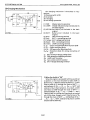
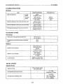
0087F011
I
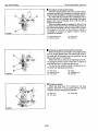
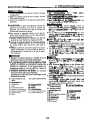
[3]
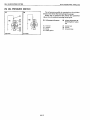
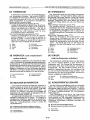
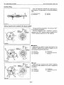
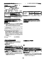
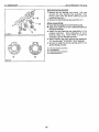
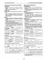
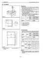
CRANKSHAFT
The crankshaft with the connecting rod converts
the reciprocating motion of the piston into the
rotating motion.
The crankshaft
is
made of tough special alloy
steel,
and the journals, pins and oil
seal
sliding portions are
induction hardened to increase the hardness for
higher wear resistance.
The front journal
is
supported by
a
solid type
bearing, the intermediate journal by
a
split type, and
the rear journal by
a
split type with thrust bearings.
The crankshaft
is
provided with an oil gallery,
through which engine oil
is
fed to the crank pin
portion, and lubricate
it.
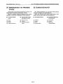
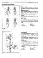
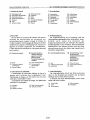
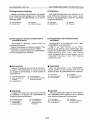
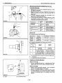
[4] PISTON AND
PISTON
RINGS
0109F017
[5]
CONNECTING ROD
The piston
is
made of aluminum alloy.
Two
recesses for
the
valves
are provided on top of
the piston.
A
fan-shaped depression
is
also given
atop the piston in order to allow combustion gas to
jet smoothly. The piston pin
is
slightly out of the
center of the piston.
In
this
design, the run-out of the
piston
at
the top and bottom dead points
can
be
reduced, thereby resulting in lower operating noise.
The piston has
a
slightly oval shape when cold (in
consideration of thermal expansion) and
a
concave
head.
Three rings are installed in grooves in the piston.
The top ring
(1)
is
a
keystone type, which
can
stand
against heavy loads, and the barrel
face
on the ring
fits well to the cylinder wall.
The second ring
(2)
is
an
undercut type, which
effectively prevents the oil from being carried up.
The
oil
ring
(3)
has chamfered contact
faces
and an
expander ring, which increase the pressure of the oil
ring against the cylinder wall.
Several grooves are cut on
the
topland to help
heat
dissipate and to prevent scuffing.
(1)
TopRing
(2)
Second Ring
(3)
OilRing
(4)
Fan-Shaped Concave
(5)
Valve Recess
Connecting rod
(2)
is
used to connect the piston
with the crankshaft. The big end of the connecting
rod has
a
crank pin bearing
(3)
(split type) and the
small end has
a
small end bushing
(1)
(solid type).
(1)
Small
End
Bushing
(2)
Connecting
Rod
(3)
Crank pin Bearing
0
109F018
M-5
La page est en cours de chargement...
La page est en cours de chargement...
La page est en cours de chargement...
La page est en cours de chargement...
La page est en cours de chargement...
La page est en cours de chargement...
La page est en cours de chargement...
La page est en cours de chargement...
La page est en cours de chargement...
La page est en cours de chargement...
La page est en cours de chargement...
La page est en cours de chargement...
La page est en cours de chargement...
La page est en cours de chargement...
La page est en cours de chargement...
La page est en cours de chargement...
La page est en cours de chargement...
La page est en cours de chargement...
La page est en cours de chargement...
La page est en cours de chargement...
La page est en cours de chargement...
La page est en cours de chargement...
La page est en cours de chargement...
La page est en cours de chargement...
La page est en cours de chargement...
La page est en cours de chargement...
La page est en cours de chargement...
La page est en cours de chargement...
La page est en cours de chargement...
La page est en cours de chargement...
La page est en cours de chargement...
La page est en cours de chargement...
La page est en cours de chargement...
La page est en cours de chargement...
La page est en cours de chargement...
La page est en cours de chargement...
La page est en cours de chargement...
La page est en cours de chargement...
La page est en cours de chargement...
La page est en cours de chargement...
La page est en cours de chargement...
La page est en cours de chargement...
La page est en cours de chargement...
La page est en cours de chargement...
La page est en cours de chargement...
La page est en cours de chargement...
La page est en cours de chargement...
La page est en cours de chargement...
La page est en cours de chargement...
La page est en cours de chargement...
La page est en cours de chargement...
La page est en cours de chargement...
La page est en cours de chargement...
La page est en cours de chargement...
La page est en cours de chargement...
La page est en cours de chargement...
La page est en cours de chargement...
La page est en cours de chargement...
La page est en cours de chargement...
La page est en cours de chargement...
La page est en cours de chargement...
La page est en cours de chargement...
La page est en cours de chargement...
La page est en cours de chargement...
La page est en cours de chargement...
La page est en cours de chargement...
La page est en cours de chargement...
La page est en cours de chargement...
La page est en cours de chargement...
La page est en cours de chargement...
La page est en cours de chargement...
La page est en cours de chargement...
La page est en cours de chargement...
La page est en cours de chargement...
La page est en cours de chargement...
La page est en cours de chargement...
La page est en cours de chargement...
La page est en cours de chargement...
La page est en cours de chargement...
La page est en cours de chargement...
La page est en cours de chargement...
La page est en cours de chargement...
La page est en cours de chargement...
La page est en cours de chargement...
La page est en cours de chargement...
La page est en cours de chargement...
La page est en cours de chargement...
La page est en cours de chargement...
La page est en cours de chargement...
La page est en cours de chargement...
La page est en cours de chargement...
La page est en cours de chargement...
La page est en cours de chargement...
La page est en cours de chargement...
La page est en cours de chargement...
La page est en cours de chargement...
La page est en cours de chargement...
La page est en cours de chargement...
La page est en cours de chargement...
La page est en cours de chargement...
La page est en cours de chargement...
La page est en cours de chargement...
La page est en cours de chargement...
La page est en cours de chargement...
La page est en cours de chargement...
La page est en cours de chargement...
La page est en cours de chargement...
La page est en cours de chargement...
La page est en cours de chargement...
La page est en cours de chargement...
La page est en cours de chargement...
La page est en cours de chargement...
La page est en cours de chargement...
La page est en cours de chargement...
La page est en cours de chargement...
La page est en cours de chargement...
La page est en cours de chargement...
La page est en cours de chargement...
La page est en cours de chargement...
La page est en cours de chargement...
La page est en cours de chargement...
La page est en cours de chargement...
La page est en cours de chargement...
La page est en cours de chargement...
La page est en cours de chargement...
La page est en cours de chargement...
La page est en cours de chargement...
La page est en cours de chargement...
La page est en cours de chargement...
La page est en cours de chargement...
La page est en cours de chargement...
La page est en cours de chargement...
La page est en cours de chargement...
La page est en cours de chargement...
La page est en cours de chargement...
La page est en cours de chargement...
La page est en cours de chargement...
La page est en cours de chargement...
La page est en cours de chargement...
La page est en cours de chargement...
La page est en cours de chargement...
La page est en cours de chargement...
La page est en cours de chargement...
La page est en cours de chargement...
La page est en cours de chargement...
La page est en cours de chargement...
La page est en cours de chargement...
La page est en cours de chargement...
La page est en cours de chargement...
La page est en cours de chargement...
La page est en cours de chargement...
La page est en cours de chargement...
La page est en cours de chargement...
La page est en cours de chargement...
La page est en cours de chargement...
La page est en cours de chargement...
La page est en cours de chargement...
La page est en cours de chargement...
La page est en cours de chargement...
La page est en cours de chargement...
La page est en cours de chargement...
La page est en cours de chargement...
La page est en cours de chargement...
La page est en cours de chargement...
La page est en cours de chargement...
La page est en cours de chargement...
La page est en cours de chargement...
La page est en cours de chargement...
La page est en cours de chargement...
La page est en cours de chargement...
La page est en cours de chargement...
La page est en cours de chargement...
La page est en cours de chargement...
La page est en cours de chargement...
La page est en cours de chargement...
La page est en cours de chargement...
La page est en cours de chargement...
La page est en cours de chargement...
La page est en cours de chargement...
La page est en cours de chargement...
La page est en cours de chargement...
La page est en cours de chargement...
La page est en cours de chargement...
La page est en cours de chargement...
La page est en cours de chargement...
La page est en cours de chargement...
-
 1
1
-
 2
2
-
 3
3
-
 4
4
-
 5
5
-
 6
6
-
 7
7
-
 8
8
-
 9
9
-
 10
10
-
 11
11
-
 12
12
-
 13
13
-
 14
14
-
 15
15
-
 16
16
-
 17
17
-
 18
18
-
 19
19
-
 20
20
-
 21
21
-
 22
22
-
 23
23
-
 24
24
-
 25
25
-
 26
26
-
 27
27
-
 28
28
-
 29
29
-
 30
30
-
 31
31
-
 32
32
-
 33
33
-
 34
34
-
 35
35
-
 36
36
-
 37
37
-
 38
38
-
 39
39
-
 40
40
-
 41
41
-
 42
42
-
 43
43
-
 44
44
-
 45
45
-
 46
46
-
 47
47
-
 48
48
-
 49
49
-
 50
50
-
 51
51
-
 52
52
-
 53
53
-
 54
54
-
 55
55
-
 56
56
-
 57
57
-
 58
58
-
 59
59
-
 60
60
-
 61
61
-
 62
62
-
 63
63
-
 64
64
-
 65
65
-
 66
66
-
 67
67
-
 68
68
-
 69
69
-
 70
70
-
 71
71
-
 72
72
-
 73
73
-
 74
74
-
 75
75
-
 76
76
-
 77
77
-
 78
78
-
 79
79
-
 80
80
-
 81
81
-
 82
82
-
 83
83
-
 84
84
-
 85
85
-
 86
86
-
 87
87
-
 88
88
-
 89
89
-
 90
90
-
 91
91
-
 92
92
-
 93
93
-
 94
94
-
 95
95
-
 96
96
-
 97
97
-
 98
98
-
 99
99
-
 100
100
-
 101
101
-
 102
102
-
 103
103
-
 104
104
-
 105
105
-
 106
106
-
 107
107
-
 108
108
-
 109
109
-
 110
110
-
 111
111
-
 112
112
-
 113
113
-
 114
114
-
 115
115
-
 116
116
-
 117
117
-
 118
118
-
 119
119
-
 120
120
-
 121
121
-
 122
122
-
 123
123
-
 124
124
-
 125
125
-
 126
126
-
 127
127
-
 128
128
-
 129
129
-
 130
130
-
 131
131
-
 132
132
-
 133
133
-
 134
134
-
 135
135
-
 136
136
-
 137
137
-
 138
138
-
 139
139
-
 140
140
-
 141
141
-
 142
142
-
 143
143
-
 144
144
-
 145
145
-
 146
146
-
 147
147
-
 148
148
-
 149
149
-
 150
150
-
 151
151
-
 152
152
-
 153
153
-
 154
154
-
 155
155
-
 156
156
-
 157
157
-
 158
158
-
 159
159
-
 160
160
-
 161
161
-
 162
162
-
 163
163
-
 164
164
-
 165
165
-
 166
166
-
 167
167
-
 168
168
-
 169
169
-
 170
170
-
 171
171
-
 172
172
-
 173
173
-
 174
174
-
 175
175
-
 176
176
-
 177
177
-
 178
178
-
 179
179
-
 180
180
-
 181
181
-
 182
182
-
 183
183
-
 184
184
-
 185
185
-
 186
186
-
 187
187
-
 188
188
-
 189
189
-
 190
190
-
 191
191
-
 192
192
-
 193
193
-
 194
194
-
 195
195
-
 196
196
-
 197
197
-
 198
198
-
 199
199
-
 200
200
-
 201
201
-
 202
202
-
 203
203
-
 204
204
-
 205
205
-
 206
206


Kubota D722-E Workshop Manual
- Catégorie
- Moteur
- Taper
- Workshop Manual
dans d''autres langues
- English: Kubota D722-E
- Deutsch: Kubota D722-E
Documents connexes
Autres documents
-
Power Fist 8242471 Le manuel du propriétaire
-
Simplicity 020333-0 Manuel utilisateur
-
Agria 5500 Le manuel du propriétaire
-
Lincoln Electric Ranger 305D Mode d'emploi
-
Miller ENPAK Le manuel du propriétaire
-
-
-
-
LG 55EF5F-L Guide de démarrage rapide
-
Husqvarna L 77 Le manuel du propriétaire