
NOTE: THIS INSTRUCTION
BOOKLET CONTAINS IMPORTANT
SAFETY INFORMATION.
PLEASE READ AND KEEP FOR
FUTURE REFERENCE.
English pg 1-28
Français pg 29-32
Español pg 33-36
Lot # 372657 05/13/15
Purchased: __________________
Be sure to give us a ring before
making any returns. 1-800-523-3987
Desk
Registry Row Collection | 412267
Need help? Visit Sauder.com to view video assembly tips or chat with a live rep.
Prefer the phone? Call 1-800-523-3987.
Share your journey!
sauder.com
The original desktop.

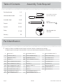
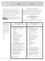
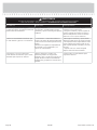
Table of Contents Assembly Tools Required
2-3
4-5
6-28
29-32
33-36
37-38
39
Part Identifi cation
Hardware Identifi cation
Assembly Steps
Français
Español
Safety
Warranty
Hammer
Not actual size
No. 2 Phillips Screwdriver
Tip Shown Actual Size
Skip the power trip.
This time.
412267 www.sauder.com/servicesPage 2
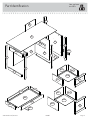
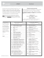
Part Identifi cation
å While not all parts are labeled, some of the parts will have a label or an inked letter on the edge
to help distinguish similar parts from each other. Use this part identifi cation to help identify similar parts.
A RIGHT END (1)
B UPPER LEFT END (1)
C LOWER LEFT END (1)
D UPRIGHT (1)
D34 PENCIL DRAWER RIGHT SIDE (1)
D35 PENCIL DRAWER LEFT SIDE (1)
D36 SMALL DRAWER RIGHT SIDE (1)
D37 SMALL DRAWER LEFT SIDE (1)
D48 FILE DRAWER RIGHT SIDE (1)
D49 FILE DRAWER LEFT SIDE (1)
D77 SMALL DRAWER BACK (1)
D78 FILE DRAWER BACK (1)
D121 PENCIL DRAWER BACK (1)
D716 DRAWER BOTTOM (2)
D991 PENCIL DRAWER BOTTOM (1)
E TOP (1)
F BOTTOM (1)
G MODESTY PANEL (1)
H BACK (1)
I BRACE (1)
J UPPER DRAWER FRONT (1)
N LOWER DRAWER FRONT (1)
R2 PENCIL DRAWER FRONT (1)
U RIGHT FRONT LEG (1)
V LEFT FRONT LEG (1)
W RIGHT REAR LEG (1)
X LEFT REAR LEG (1)
Y CENTER LEG (1)
Z EXTENSION BLOCK (1)
M67 DRAWER BRACE (1)
M74 END MOLDING (1)

Part Identifi cation
Now you know
our ABCs.
412267www.sauder.com/services
Page 3
A
B
C
D
E
F
G
H
U
W
X
V
I
Z
Y
D34
D35
D121
D716
D716
D991
D36
D48
D49
D77
D78
D37
R2
N
J
M67
M74

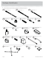
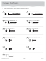
Hardware Identifi cation
å Screws are shown actual size. You may receive extra hardware with your unit.
GLUE - 1
KK
CAM COVER - 4
II
TACK GLIDE - 5
LL
WOOD DOWEL - 9
PP
FILE DRAWER
FRONT BRACKET - 2
MM
METAL BRACE - 1
TT
FOOT - 5
QQ
PULL - 2
SS
KNOB - 2
VV
WW
BACKPLATE - 2
CORNER ACCENT - 3
UU
40CB
CABINET LEFT - 3
40CA
CABINET RIGHT - 3
40CC
DRAWER RIGHT - 3
40CD
DRAWER LEFT - 3
HIDDEN CAM - 24
1F
CAM SCREW - 13
8F
CAM DOWEL- 11
2F
412267 www.sauder.com/servicesPage 4
FILE GLIDE - 2
4B
PENCIL DRAWER
FRONT BRACKET - 1
OO
DRAWER FRONT
BRACKET - 1
NN

Hardware Identifi cation
å Screws are shown actual size. You may receive extra hardware with your unit.
412267www.sauder.com/services
Page 5
EEE
SILVER 1/2" MACHINE SCREW - 5
AAA
GOLD 1" MACHINE SCREW - 2
SILVER 1-1/8" FLAT HEAD SCREW -2
ZZ
BLACK 2-1/4" FLAT HEAD SCREW - 3
XX
SILVER 2" FLAT HEAD SCREW - 4
YY
BBB
BLACK 7/8" MACHINE SCREW - 2
FFF
GOLD 5/16" FLAT HEAD SCREW - 24
CCC
BLACK 9/16" FLAT HEAD SCREW - 2
DDD
BROWN 9/16" LARGE HEAD SCREW - 14
GGG
NAIL - 20
30S
BLACK 1-9/16" FLAT HEAD SCREW - 13

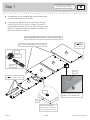
Step 1
Look for this icon. It means a
video assembly tip is available at
www.sauder.com/services/tips
å
Assemble your unit on a carpeted fl oor or on the empty carton
to avoid scratching your unit or the fl oor.
å
Push twenty-four HIDDEN CAMS (1F) into the ENDS (A and C),
UPRIGHT (D), BOTTOM (F), MODESTY PANEL (G), BRACE (I)
and DRAWER BRACE (M67) Then, insert the metal end of a CAM
DOWEL (2F) into each HIDDEN CAM, except in the LOWER LEFT
END (C) and MODESTY PANEL (G).
412267 www.sauder.com/servicesPage 6
I
C
A
D
F
G
Arrow
1F
2F
Insert the metal end of the CAM
DOWEL into the HIDDEN CAM.
Arrow
Do not tighten the HIDDEN CAMS in this step.
Do not insert CAM DOWELS into these edges.
Do not insert
CAM DOWELS
into this edge.
Do not insert CAM
DOWELS into these edges.
Arrow
The arrow in the HIDDEN
CAM must point toward the
hole in the edge of the board.
Hole
(11 used)
(24 used)
M67

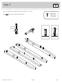
å
Turn thirteen CAM SCREWS (8F) into the LEGS (U, V, X, and Y).
å
NOTE: Be sure to use the exact holes shown.
Step 2
412267www.sauder.com/services
Page 7
Y
U
V
X
8F
8F
(13 used)
Remember:
Righty tighty.
Lefty loosey.

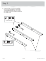
Step 3
å
Fasten the CORNER ACCENTS (UU) to the FRONT
LEGS (U, V, and Y). Use two BLACK 7/8" MACHINE
SCREWS (BBB) through the FRONT LEGS (U and Y).
Use a SILVER 1/2" MACHINE SCREW (EEE) through the
LEFT FRONT LEG (V).
412267 www.sauder.com/servicesPage 8
V
Y
U
UU
UU
Angled edge
BLACK 7/8" MACHINE SCREW
(2 used in this step)
BBB
SILVER 1/2" MACHINE SCREW
(1 used in this step)
EEE

å
Fasten the RIGHT FRONT LEG (U) to the RIGHT END (A)
and the CENTER LEG (Y) to the UPRIGHT (D). Tighten six
HIDDEN CAMS.
Step 4
412267www.sauder.com/services
Page 9
U
A
D
Y
Angled edge
Angled edge
Edge with CAM DOWELS
1
2
Surface with
HIDDEN CAMS
Surface with
HIDDEN CAMS

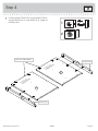
Step 5
å
Carefully turn the RIGHT END (A) over.
å
Turn two BLACK 9/16" FLAT HEAD SCREWS (CCC) into
the END (A) until the shoulders of the SCREWS rest on
the surface of the END.
å
Slide the END MOLDING (M74) onto the END (A). Line
up the groove in the MOLDING over the heads of the
SCREWS in the END and slide it until it is against the
RIGHT FRONT LEG (U).
å
Fasten the RIGHT REAR LEG (W) to the RIGHT END (A).
Use three BLACK 2 1/4" FLAT HEAD SCREWS (XX).
412267 www.sauder.com/servicesPage 10
W
A
U
Angled edge
Apply pressure with your hands
as you guide the MOLDINGS over
the SCREWS and onto the END.
Shoulder
BLACK 2-1/4" FLAT HEAD SCREW
(3 used in this step)
XX
BLACK 9/16" FLAT HEAD SCREW
(2 used in this step)
CCC
M74
M74

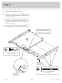
å
First, fi ll the holes in one end of the UPPER LEFT END (B) 1/4 to
1/2 full with GLUE (KK). Then, insert two WOOD DOWELS (PP)
into these holes. Wipe away the excess GLUE.
å
Repeat this step for the other end of the UPPER LEFT END (B)
and both ends of the LOWER LEFT END (C) and BRACE (I).
å
Now, fasten the BRACE (I) to UPPER LEFT END (B). Use two
SILVER 1-1/8" FLAT HEAD SCREWS (ZZ).
Step 6
412267www.sauder.com/services
Page 11
Surface with
HIDDEN CAMS
I
+
+
Surface with
HIDDEN CAMS
C
B
KK
KK
PP
PP
Fill the holes 1/4 to 1/2 full with GLUE.
Inspect the parts thoroughly before
assembling. Disassembly of glued
parts is extremely di cult.
Caution
!
Edge with HIDDEN CAMS
(8 used)
SILVER 1-1/8" FLAT HEAD SCREW
(2 used in this step)
ZZ
The holes should be
closer to this edge.
If the UPPER LEFT END (B) has an
unfi nished surface, it should be facing up.

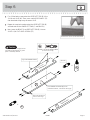
Step 7
å
First, fi ll the four holes in the edge of the LEFT REAR LEG (X)
1/4 to 1/2 full with GLUE (KK). Then, insert the WOOD DOWELS
in the ENDS (C and B) and BRACE (I) into the holes of the LEG.
Wipe away the excess GLUE.
å
NOTE: Be sure the CAM SCREWS insert into the holes in the
short edges of the LOWER LEFT END (C) and BRACE (I).
å
Fasten the LEFT REAR LEG (X) to the LOWER LEFT END (C)
and BRACE (I). Tighten two HIDDEN CAMS.
å
Repeat this step for the LEFT FRONT LEG (V) making sure all
HIDDEN CAMS are tight.
412267 www.sauder.com/servicesPage 12
V
I
C
B
X
KK
Fill the holes 1/4 to 1/2 full with GLUE.
Inspect the parts thoroughly before
assembling. Disassembly of glued
parts is extremely di cult.
Caution
!
Surface with
HIDDEN CAMS
Surface with
HIDDEN CAMS
Angled edge
Angled edge

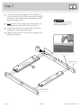
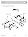
å
Fasten two CABINET RIGHTS (40CA) and two CABINET
LEFTS (40CB) to the RIGHT END (A) and UPRIGHT (D). Use
eight GOLD 5/16" FLAT HEAD SCREWS (FFF) through holes
#1 and #3.
Step 8
412267www.sauder.com/services
Page 13
A
D
1
2
3
4
4
3
2
1
Angled edge
Angled edge
Edge with CAM DOWELS
Roller end
Roller end
GOLD 5/16" FLAT HEAD SCREW
(8 used in this step)
FFF
4
3
2
1
1
2
3
4

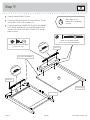
Step 9
å
Carefully fl ip the UPRIGHT (D) over.
å
Fasten the EXTENSION BLOCK (Z) to the UPRIGHT (D). Use
two SILVER 2" FLAT HEAD SCREWS (YY).
å
Fasten the remaining CABINET RIGHT (40CA) and CABINET
LEFT (40CB) to the BRACE (I) and EXTENSION BLOCK (Z).
Use four GOLD 5/16" FLAT HEAD SCREWS (FFF) through
holes #1 and #3.
412267 www.sauder.com/servicesPage 14
Z
Finished
surface
D
I
1
2
3
4
4
3
2
1
Angled edge
Angled edge
Edge with CAM DOWELS
Roller end
GOLD 5/16" FLAT HEAD SCREW
(4 used in this step)
FFF
SILVER 2" FLAT HEAD SCREW
(2 used for the EXTENSION BLOCK)
YY
Roller end
Don't worry. It isn't
Rome. This can be built
in a day.

å
Insert a WOODEN DOWEL (PP) into the hole in
the TOP (E).
å
Fasten the BRACE (I) to the TOP (E). Tighten two
HIDDEN CAMS.
å
NOTE: Be sure the WOODEN DOWEL inserts into
the hole in the LEG.
å
Fasten the MODESTY PANEL (G) to the LEFT
REAR LEG (X). Tighten three HIDDEN CAMS.
Step 10
412267www.sauder.com/services
Page 15
X
G
E
I
PP
Surface
with
HIDDEN
CAMS
Start Tighten
Arrow
Minimum
190 degrees
Caution
Risk of damage or
injury. HIDDEN CAMS
must be completely
tightened. HIDDEN
CAMS that are not
completely tightened
may loosen, and parts
may separate. To
completely tighten:
Arrow
Maximum
210 degrees
Curved edge
Do not stand the unit upright without the
BACK fastened. The unit may collapse.
Caution
Surface with holes

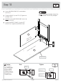
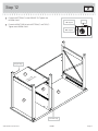
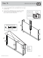
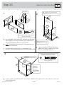
Step 11
å
Fasten the UPRIGHT (D) to the TOP (E). Tighten two
HIDDEN CAMS.
å
Fasten the UPRIGHT (D) to the MODESTY PANEL (G). Use
two SILVER 2" FLAT HEAD SCREWS (YY).
å
Fasten the METAL BRACE (TT) to the LEFT LEGS (V and X).
Use four BROWN 9/16" LARGE HEAD SCREWS (DDD).
412267 www.sauder.com/servicesPage 16
TT
D
G
E
V
X
Arrow
Minimum
190 degrees
Maximum
210 degrees
SILVER 2" FLAT HEAD SCREW
(2 used in this step)
YY
BROWN 9/16" LARGE HEAD SCREW
(4 used for the METAL BRACE)
DDD

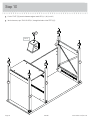
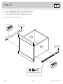
å
Fasten the BOTTOM (F) to the UPRIGHT (D). Tighten two
HIDDEN CAMS.
å
Fasten the RIGHT END (A) to the BOTTOM (F) and TOP (E).
Tighten four HIDDEN CAMS.
Step 12
412267www.sauder.com/services
Page 17
D
E
F
A
Surface with
HIDDEN CAMS
Finished edge
Angled edge
Arrow
Minimum
190 degrees
Maximum
210 degrees

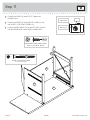
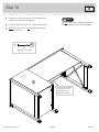
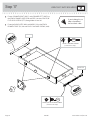
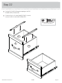
Step 13
å
Push a FOOT (QQ) over the bottom edge of each LEG (U, V, W, X, and Y).
å
With a hammer, tap a TACK GLIDE (LL) through the holes of the FEET (QQ).
412267 www.sauder.com/servicesPage 18
U
V
W
X
Y
LL
QQ
(5 used)

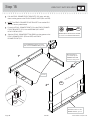
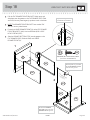
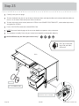
å
Carefully turn your unit over onto its front edge and lay
the BACK (H) over the large opening.
å
Fasten the BACK (H) to your unit using the NAILS (GGG).
å
NOTE: Be sure the BACK is not hanging over the top
surface of the TOP.
Step 14
412267www.sauder.com/services
Page 19
The edge of the BACK
should be even with
the BOTTOM and
UPRIGHT surfaces.
H
Finished
surface
NAIL
(20 used in this step)
GGG
Do not stand the unit upright without the
BACK fastened. The unit may collapse.
Caution

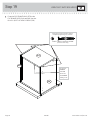
Step 15
å
Pull the PENCIL DRAWER FRONT BRACKETS (OO) apart and slide
them into the grooves in the PENCIL DRAWER SIDES (D34 and D35).
å
NOTE: The PENCIL DRAWER FRONT BRACKETS are marked "RH"
and "LH" for easy identifi cation.
å
Fasten the PENCIL DRAWER FRONT (R2) to the PENCIL DRAWER
FRONT BRACKETS (OO). Use two BROWN 9/16" LARGE
HEAD SCREWS (DDD).
å
Slide the PENCIL DRAWER BOTTOM (D991) into the grooves in the
PENCIL DRAWER SIDES (D34 and D35) and PENCIL
DRAWER FRONT (R2).
412267 www.sauder.com/servicesPage 20
Pull the BRACKETS apart and slide
them into the DRAWER SIDE grooves.
Unfi nished surface
With the palm of
your hand, tap the
DRAWER BOTTOM
down into the groove.
1
st
2
nd
OO
R2
R2
OO
D34
D238
D35
Groove
BROWN 9/16" LARGE HEAD SCREW
(2 used for the FRONT BRACKETS)
DDD
D34
D991
D35
Be sure the DRAWER
BOTTOM inserts into the
DRAWER FRONT groove.
VIEW THE T-SLOT BOX VIDEO
La page est en cours de chargement...
La page est en cours de chargement...
La page est en cours de chargement...
La page est en cours de chargement...
La page est en cours de chargement...
La page est en cours de chargement...
La page est en cours de chargement...
La page est en cours de chargement...
La page est en cours de chargement...
La page est en cours de chargement...
La page est en cours de chargement...
La page est en cours de chargement...
La page est en cours de chargement...
La page est en cours de chargement...
La page est en cours de chargement...
La page est en cours de chargement...
La page est en cours de chargement...
La page est en cours de chargement...
La page est en cours de chargement...
La page est en cours de chargement...
-
 1
1
-
 2
2
-
 3
3
-
 4
4
-
 5
5
-
 6
6
-
 7
7
-
 8
8
-
 9
9
-
 10
10
-
 11
11
-
 12
12
-
 13
13
-
 14
14
-
 15
15
-
 16
16
-
 17
17
-
 18
18
-
 19
19
-
 20
20
-
 21
21
-
 22
22
-
 23
23
-
 24
24
-
 25
25
-
 26
26
-
 27
27
-
 28
28
-
 29
29
-
 30
30
-
 31
31
-
 32
32
-
 33
33
-
 34
34
-
 35
35
-
 36
36
-
 37
37
-
 38
38
-
 39
39
-
 40
40


Sauder 412267 Manuel utilisateur
- Taper
- Manuel utilisateur
- Ce manuel convient également à
dans d''autres langues
- English: Sauder 412267 User manual
- español: Sauder 412267 Manual de usuario
Documents connexes
-
Sauder 423408 Mode d'emploi
-
-
-
-
Unbranded 426152 Mode d'emploi
-
 Sauder Woodworking 420267 Manuel utilisateur
-
-
-
-
