
NOTE: THIS INSTRUCTION
BOOKLET CONTAINS IMPORTANT
SAFETY INFORMATION.
PLEASE READ AND KEEP FOR
FUTURE REFERENCE.
Enlish p 1-19
Français p 20-22
Español p 23-25
Lot # 387426 12/29/15
Purchased: __________________
Be sure to ive us a rin before
makin any returns. 1-800-523-3987
Utility Stand
Shoal Creek Collection | Model 409944
Need help? Visit Sauder.com to view video assembly tips or chat with a live rep.
Prefer the phone? Call 1-800-523-3987.
Share your journey!
sauder.com
For things 'n such.

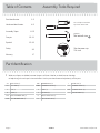
Table of Contents Assembly Tools Required
2-3
4-5
6-19
20-22
23-25
26
27
Part Identifi cation
Hardware Identifi cation
Assembly Steps
Français
Español
Safety
Warranty
Hammer
Not actual size
No. 2 Phillips Screwdriver
Tip Shown Actual Size
Skip the power trip.
This time.
409944 www.sauder.com/servicesPae 2
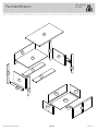
Part Identifi cation
å While not all parts are labeled, some of the parts will have a label or an inked letter on the ede
to help distinuish similar parts from each other. Use this part identifi cation to help identify similar parts.
A2 RIGHT END (1)
B2 LEFT END (1)
C TOP (1)
D BACK (1)
D14 RIGHT DRAWER SIDE (1)
D15 LEFT DRAWER SIDE (1)
D61 DRAWER BACK (1)
D985 DRAWER BOTTOM (1)
E SHELF (1)
F BOTTOM (2)
G RIGHT FRONT LEG (1)
H LEFT FRONT LEG (1)
I REAR LEG (2)
J2 DRAWER FRONT (1)
M67 DRAWER BRACE (1)
O END MOLDING (2)

Part Identifi cation
Now you know
our ABCs.
409944www.sauder.com/services
Pae 3
A2
B2
C
D
E
F
G
H
I
J2
O
O
I
F
M67
D61
D14
D15
D985

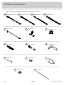
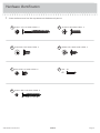
Hardware Identifi cation
å Screws are shown actual size. You may receive extra hardware with your unit.
409944 www.sauder.com/servicesPae 4
FILE GLIDE - 2
4B
FILE BRACKET - 1
57G
HIDDEN CAM - 17
1F
CAM COVER - 1
BB
METAL PIN - 4
W
PULL - 2
Z
CAM SCREW - 4
8F
SLIDE CAM - 2
X
CAM DOWEL - 13
2F
FILE ROD - 2
CC
FILE BRACKET - 1
12B
40CA
CABINET RIGHT - 1
40CB
CABINET LEFT - 1
40CC
DRAWER RIGHT - 1
40CD
DRAWER LEFT - 1

Hardware Identifi cation
å Screws are shown actual size. You may receive extra hardware with your unit.
409944www.sauder.com/services
Pae 5
SILVER 3/4" MACHINE SCREW - 4
FF
BROWN 7/16" LARGE HEAD SCREW - 4
HH
BLACK 2-1/4" FLAT HEAD SCREW - 4
EE
GOLD 5/16" FLAT HEAD SCREW - 8
II
NAIL - 20
JJ
BLACK 9/16" FLAT HEAD SCREW - 4
GG
30S
BLACK 1-9/16" FLAT HEAD SCREW - 5

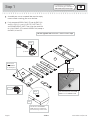
Step 1
Look for this icon. It means a
video assembly tip is available at
www.sauder.com/services/tips
å
Assemble your unit on a carpeted fl oor or on the empty
carton to avoid scratchin your unit or the fl oor.
å
Push seventeen HIDDEN CAMS (1F) into the ENDS (A2
and B2), LEGS (G, H, and I), SHELF (E), BOTTOMS (F),
and DRAWER BRACE (M67). Then, insert the metal end
of a CAM DOWEL (2F) into each HIDDEN CAM, except in
the ENDS (A2 and B2).
409944 www.sauder.com/servicesPae 6
(17 used)
(12 used)
Arrow
1F
2F
Do not tihten the HIDDEN CAMS in this step.
Do not insert
CAM DOWELS
into these parts.
A2
B2
E
F
G
H
I
I
F
M67
Arrow
Arrow
1F
The arrow in the HIDDEN
CAM must point toward the
hole in the ede of the board.
Hole
Insert the metal end of the CAM
DOWEL into the HIDDEN CAM.
Arrow

å
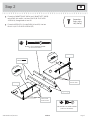
Fasten the CABINET RIGHT (40CA) and CABINET LEFT (40CB)
to the ENDS (A2 and B2). Use four GOLD 5/16" FLAT HEAD
SCREWS (II) throuh holes #1 and #3.
å
Fasten the REAR LEGS (I) to the ENDS (A2 and B2). Use four
BLACK 2-1/4" FLAT HEAD SCREWS (EE).
Step 2
409944www.sauder.com/services
Pae 7
1
2
3
4
A2
B2
I
I
BLACK 2-1/4" FLAT HEAD SCREW
(4 used for the LEGS)
EE
Anled ede
These holes
must be here.
Roller end
Roller end
Surface without
HIDDEN CAMS
These holes
must be here.
1
2
3
4
Remember:
Rihty tihty.
Lefty loosey.
GOLD 5/16" FLAT HEAD SCREW
(4 used for the RAILS)
II

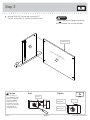
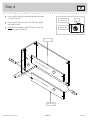
Step 3
å
With the REAR LEG (I) on the fl oor, fasten the LEFT
END (B2) to the SHELF (E). Tihten two HIDDEN CAMS.
409944 www.sauder.com/servicesPae 8
B2
E
I
Finished ede
Start Tighten
Arrow
Minimum
190 derees
Caution
Risk of damae or
injury. HIDDEN CAMS
must be completely
tihtened. HIDDEN
CAMS that are not
completely tihtened
may loosen, and parts
may separate. To
completely tihten:
Arrow
Maximum
210 derees
Do not stand the unit upriht without the
BACK fastened. The unit may collapse.
Caution
Surface with HIDDEN CAMS

å
Insert a METAL PIN (W) into the holes of each short ede
of the BOTTOMS (F).
å
Fasten the BOTTOMS (F) to the LEFT END (B2). Tihten
two HIDDEN CAMS.
å
NOTE: Be sure the PINS in the BOTTOMS (F) insert into
the holes in the LEFT END (B2).
Step 4
409944www.sauder.com/services
Pae 9
Surface with HIDDEN CAMS
B2
W
F
W
Finished ede
Finished ede
Surface with HIDDEN CAMS
F
Arrow
Minimum
190 derees
Maximum
210 derees

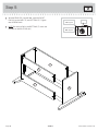
Step 5
å
With the REAR LEG (I) on the fl oor, fasten the RIGHT
END (A2) to the SHELF (E) and BOTTOMS (F). Tihten
four HIDDEN CAMS.
å
NOTE: Be sure the PINS in the BOTTOMS (F) insert into
the holes in the RIGHT END (A2).
409944 www.sauder.com/servicesPae 10
A2
E
F
F
I
Arrow
Minimum
190 derees
Maximum
210 derees

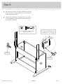
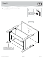
å
Turn four BLACK 9/16" FLAT HEAD SCREWS (GG) into the
ENDS (A2 and B2) until the shoulders of the SCREWS rest
on the surfaces of the ENDS.
å
Slide the END MOLDINGS (O) onto the ENDS (A2 and B2).
Line up the rooves in the MOLDINGS over the heads of
the SCREWS in the ENDS.
Step 6
409944www.sauder.com/services
Pae 11
Apply pressure with your hands
as you uide the MOLDINGS over
the SCREWS and onto the ENDS.
O
A2
B2
GG
GG
O
Shoulder
Shoulder
BLACK 9/16" FLAT HEAD SCREW
(4 used in this step)
GG

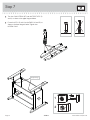
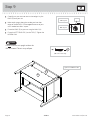
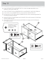
Step 7
å
Turn four CAM SCREWS (8F) into the FRONT LEGS (G
and H) as shown in the upper diaram below.
å
Fasten the LEGS (G and H) to the ENDS (A2 and B2) as
shown in the lower diaram below. Tihten four
HIDDEN CAMS.
409944 www.sauder.com/servicesPae 12
8F
G
H
A2
B2
G
H
Anled ede
1
2

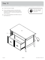
å
Fasten the TOP (C) to the LEGS (G, H, and I). Tihten
three HIDDEN CAMS.
Step 8
409944www.sauder.com/services
Pae 13
C
G
H
I
The HIDDEN CAM in this LEG
will be tihtened in the next step.
Finished ede
Arrow
Minimum
190 derees
Maximum
210 derees
Surface with holes

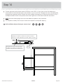
Step 9
å
Carefully turn your unit over onto its front edes. Lay the
BACK (D) over your unit.
å
Make equal marins alon the two lon and two short
edes of the BACK (D). Push on opposite corners of your
unit if needed to make it "square".
å
Fasten the BACK (D) to your unit usin the NAILS (JJ).
å
Fasten the LEFT REAR LEG (I) to the TOP (C). Tihten the
HIDDEN CAM.
409944 www.sauder.com/servicesPae 14
Tihten this HIDDEN CAM.
C
D
I
Arrow
Minimum
190 derees
Maximum
210 derees
Do not stand the unit upriht without the
BACK fastened. The unit may collapse.
Caution
NAIL
(20 used in this step)
JJ

Step 10
409944www.sauder.com/services
Pae 15
å
Insert the DRAWER SIDES (D14 and D15) at an angle
into the slot at each end of the DRAWER FRONT (J2).
å
Slide the DRAWER BOTTOM (D985) into the
grooves in the DRAWER SIDES (D14 and D15) and
DRAWER FRONT (J2).
å
Fasten the DRAWER BRACE (M67) to the DRAWER
FRONT (J2). Tighten one HIDDEN CAM.
å
Fasten the DRAWER BACK (D61) to the DRAWER
SIDES (D14 and D15) and DRAWER BRACE (M67). Use
five BLACK 1-9/16" FLAT HEAD SCREWS (30S).
Surface with
HIDDEN CAM
12
34
Be sure the DRAWER
BOTTOM inserts into the
DRAWER FRONT roove.
Groove
Arrow
Maximum
210 derees
Minimum
190 derees
Start each screw a few turns before
completely tihtenin any of them.
BLACK 1-9/16" FLAT HEAD SCREW
(5 used in this step)
J2
J2
M67
J2
M67
VIEW THE T-LOCK BOX VIDEO
D15
D14
D15
D985
D14
D14
D15
D61
Unfi nished
surface
30S
Be sure the
DRAWER
BOTTOM
inserts into
the DRAWER
BACK roove.
The tabs should insert freely
into the slots. Gently tilt the
DRAWER SIDES side to side
until the tabs slip into the slots.
With the palm of your hand,
tap the DRAWER BOTTOM
down into the roove.

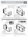
Step 11
å
Insert a SLIDE CAM (X) into the DRAWER SIDES (D14 and D15).
å
Fasten the DRAWER RIGHT (40CC) and DRAWER LEFT (40CD)
to the DRAWER SIDES (D14 and D15). Use four GOLD 5/16"
FLAT HEAD SCREWS (II) throuh holes #2 and #4.
å
NOTE: The screw head in the CAM must be visible throuh the
slotted hole in the SLIDE.
409944 www.sauder.com/servicesPae 16
X
X
D14
D15
Roller end
Roller end
1
2
3
4
1
2
3
4
GOLD 5/16" FLAT HEAD SCREW
(4 used in this step)
II
Screw head - turn CAM to line up holes in
the SLIDES with holes in DRAWER SIDES

å
Fasten a FILE BRACKET (57G) to the DRAWER FRONT (J2) as shown in the upper diaram below. Use two
BROWN 7/16" LARGE HEAD SCREWS (HH).
å
Fasten a FILE BRACKET (12B) to the DRAWER BACK (D61). Use two BROWN 7/16" LARGE HEAD SCREWS (HH).
å
Fasten two PULLS (Z) to the DRAWER FRONT (J2). Use four SILVER 3/4" MACHINE SCREWS (FF).
å
Press one of the FILE GLIDES (4B) over the RIGHT DRAWER SIDE (D14) as shown in the lower diaram below. The
FILE GLIDES are necessary to han fi les.
å
Slide the FILE RODS (CC) throuh the holes in the FILE BRACKETS (57G and 12B) and into the FILE GLIDE (4B) on
the RIGHT DRAWER SIDE (D14).
å
Slide another FILE GLIDE (4B) onto the other end of the FILE RODS (CC), then press this FILE GLIDE over the
LEFT DRAWER SIDE (D15).
Step 12
409944www.sauder.com/services
Pae 17
J2
Z
12B
12B
CC
4B
4B
D61
D15
57G
57G
SILVER 3/4" MACHINE SCREW
(4 used for the PULLS)
FF
BROWN 7/16" LARGE HEAD SCREW
(4 used for the FILE BRACKETS)
HH
CC
D14
Want options? Customize
your item with add-on
hardware kits available
on sauder.com.

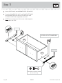
Step 13
å
Carefully stand your unit upriht.
å
To insert the drawer into your unit, tip the front of the
drawer down and drop the rollers on the drawer behind
the rollers on the unit. Lift the front of the drawer up and
slide it into the unit.
å
Push a CAM COVER (BB) onto the HIDDEN CAM on the
RIGHT REAR LEG (I).
409944 www.sauder.com/servicesPae 18
I
BB
50 lbs.
25 lbs.
35 lbs.
Pro Tip: Lift with your
les. And, you know,
your arms.

å
To make adjustments to the drawers, loosen SCREW #4 in the SLIDES a 1/4 turn, then turn the CAM clockwise or
counter-clockwise. Notice how the drawer raises or lowers as you turn the CAM. The hiher the screw in the oblon hole,
the hiher your drawer front will be. The lower the screw, the lower the drawer front. By adjustin the drawers this way, it
will help the DRAWER FRONTS line up better when closed. Tihten the SCREW when fi nished with adjustments.
å
NOTE: Please read the back paes of the instruction booklet for important safety information.
å
This completes assembly. Clean with your favorite furniture polish or a damp cloth. Wipe dry.
Step 14
409944www.sauder.com/services
Pae 19
And to celebrate, why not share your success story?
The hiher the screw in the oblon hole,
the hiher your drawer front will be. The
lower the screw, the lower the drawer front.
Loosen screw #4 a 1/4 turn, turn the cam a 1/4 turn
maximum in both the clockwise and counter-clockwise
directions to make adjustments, and then tihten screw #4.
Cam
43

A l’usae exclusif du
Canada Noter la date
d’achat de cet élément
et conserver le livret
pour future référence.
Pour contacter Sauder
en ce qui concerne cet
élément, faire référence
au numéro de lot et
numéro de modèle en
appelant notre numéro
sans frais.
Lot nº : ____________
Date de
l’achat: ____________
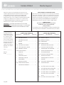
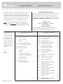
LISTE DE PIÈCES
REFERENCE DESCRIPTION QUANTITÉ
LISTE DE PIÈCES
REFERENCE DESCRIPTION QUANTITÉ
NOUS SOMMES LA POUR VOUS AIDER!
Nous faisons de notre mieux pour nous assurer que votre meuble
arrive dans d’excellentes conditions. Nos représentants du service
Clientèle sont aimables et prêts à vous aider au cas où une pièce
aurait été endommaée ou manquerait (ou si vous aviez besoin
d’aide pour l’assemblae). NE RAMENEZ PAS LE MEUBLE AU
MAGASIN. Au Canada, composez ce numéro d’appel ratuit:
1-800-523-3987
Du lundi au vendredi, de 9 heures du matin à
5:30 heures du soir (horaire Côte Est)
(sauf jours fériés)
Si une pièce a besoin d’être remplacée, la pièce de remplacement
sera envoyée dans les 48 heures. (Sauf week-ends et jours fériés)
Utilisez les instructions d’assemblae en français avec les
schémas étape par étape du manuel d’instruction en anlais.
Chaque étape en français correspond à la même étape
en anlais. La pièce devant être attachée à l’élément est
représentée en ris sur les schémas de chaque étape pour plus
de précision. Comparer la “Liste de pièces” ci-dessous avec
la “PART IDENTIFICATION” du manuel en anlais pour vous
familiariser avec les pièces avant l’assemblae.
REMARQUE : CE MANUEL D’INSTRUCTIONS CONTIENT
D’IMPORTANTES INFORMATIONS RELATIVES À LA SÉCURITÉ.
À LIRE ET CONSERVER POUR TOUTE RÉFÉRENCE FUTURE.
Meuble d'appointModèle 409944
40CA
ÉLÉMENT DROITE.......................................................1
40CB
ÉLÉMENT GAUCHE ...................................................1
40CC
TIROIR DROIT .................................................................1
40CD
TIROIR GAUCHE ...........................................................1
4B ARMATURE POUR DOSSIERS .........................2
12B CONSOLE POUR DOSSIERS .............................1
1F EXCENTRIQUE ESCAMOTABLE ...................17
2F CHEVILLE D'EXCENTRIQUE ........................... 13
8F VIS D'EXCENTRIQUE ...............................................4
57G CONSOLE POUR DOSSIERS .............................1
W GOUPILLE EN MÉTAL .............................................4
X EXCENTRIQUE DE COULISSE .........................2
Z POIGNÉE ............................................................................2
BB COUVERCLE D'EXCENTRIQUE ........................1
CC TIGE DE DOSSIER ......................................................2
EE VIS TÊTE PLATE 57 mm NOIRE .....................4
FF VIS À MÉTAUX 19 mm ARGENTÉE ..............4
GG VIS TÊTE PLATE 14 mm NOIRE ......................4
HH VIS TÊTE LARGE 11 mm MARRON ..............4
II VIS TÊTE PLATE 8 mm DORÉE ......................8
JJ CLOU ................................................................................20
30S VIS TÊTE PLATE 40 mm NOIRE ....................5
A2 EXTRÉMITÉ DROITE ..................................................1
B2 EXTRÉMITÉ GAUCHE ...............................................1
C DESSUS ...............................................................................1
D ARRIÈRE ..............................................................................1
D14 CÔTÉ DROIT DE TIROIR ........................................1
D15 CÔTÉ GAUCHE DE TIROIR ..................................1
D61 ARRIÈRE DE TIROIR ...................................................1
D985
FOND DE TIROIR ..........................................................1
E TABLETTE ..........................................................................1
F DESSOUS ..........................................................................2
G PIED AVANT DROIT ....................................................1
H PIED AVANT GAUCHE .............................................1
I PIED ARRIÈRE ................................................................2
J2 DEVANT DE TIROIR ....................................................1
M67 ENTRETOISE DE TIROIR ........................................1
O MOULURE D’EXTRÉMITÉ .....................................2
409944 www.sauder.com/servicesPae 20
La page est en cours de chargement...
La page est en cours de chargement...
La page est en cours de chargement...
La page est en cours de chargement...
La page est en cours de chargement...
La page est en cours de chargement...
La page est en cours de chargement...
La page est en cours de chargement...
-
 1
1
-
 2
2
-
 3
3
-
 4
4
-
 5
5
-
 6
6
-
 7
7
-
 8
8
-
 9
9
-
 10
10
-
 11
11
-
 12
12
-
 13
13
-
 14
14
-
 15
15
-
 16
16
-
 17
17
-
 18
18
-
 19
19
-
 20
20
-
 21
21
-
 22
22
-
 23
23
-
 24
24
-
 25
25
-
 26
26
-
 27
27
-
 28
28


dans d''autres langues
- English: Sauder 409944 User manual
- español: Sauder 409944 Manual de usuario
Documents connexes
-
Sauder 409942 Assembly Instructions Manual
-
-
-
-
-
-
-
-
-
