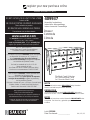
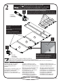
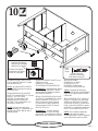
Sauder 409937 Assembly Instructions Manual
- Taper
- Assembly Instructions Manual

Mon-Fri - 9am-5:30pm ET
United States and Canada (except holidays)
Consumer Services 1-800-523-3987
Pour obtenir une service immédiate, notre site Internet
est disponible 24 heures sur 24, 7 jours sur 7,
pour commander des pièces de rechange,
des conseils d’assemblage, enregistrer tout produit
ou visualiser des produits Sauder.
Du lundi au vendredi de 9 h 00 à 17 h 30
(heure normale de l’est)
Aux États-Unis et au Canada (sauf jours fériés)
Services aux consommateurs 1-800-523-3987
Para el servicio inmediata, nuestro sitio Web está
disponible las 24 horas al día,
7 días a la semana para pedir piezas de repuesto,
consejos de ensamblaje, registrar su producto y
ver los productos Sauder.
De lunes a viernes de 9 a.m. a 5:30 p.m. (hora del este)
Estados Unidos y Canadá (salvo días festivos)
Servicios del consumidor 1-800-523-3987
register your new purchase online
www.sauder.com
DO NOT RETURN YOUR UNIT TO THE STORE
Contact us fi rst
NE PAS RAPPORTER L’ÉLÉMENT AU MAGASIN
Nous contacter en premier
NO DEVUELVA SU UNIDAD A LA TIENDA
Comuníquese con nosotros primero
Most replacement parts ship from our
facility in one or two business days.
Les pièces de rechange sont, pour la plupart, expédiées de
notre établissement dans les un à deux jours ouvrables.
La mayoría de piezas de repuesto son enviadas desde
nuestra instalación en uno o dos días laborables.
www.sauder.com
For immediate service, our website is available
24 hours a day, 7 days a week
to order replacement parts, access assembly tips,
register your product, and view Sauder products.
NOTE
This instruction booklet contains IMPORTANT safety information.
Please read and keep for future reference.
REMARQUE
Ce manuel d’instructions contient D’IMPORTANTES informations
relatives à la sécurité.
À lire et conserver pour toute référence future.
NOTA
Este folleto de instrucciones contiene información IMPORTANTE sobre
la seguridad. Por favor lea y guárdelo para referencia en
el futuro.
409937
Assembly Instructions
Instructions d’assemblage
Instrucciones de Ensamblaje
Dresser
Commode
Cómoda
Lot #: 352388
Date Purchased: ____________
04 / 12 / 13
The Shoal Creek Collection
La Collection Shoal Creek
La Colección Shoal Creek

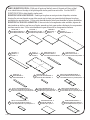
PARTS IDENTIFICATION: While not all parts are labeled, some of the parts will have a label
or an inked letter on the edge to help distinguish similar parts from each other. Use this PARTS
IDENTIFICATION to help identify similar parts.
IDENTIFICATION DES PIÈCES : Tandis que les pièces ne sont pas toutes étiquetées, certaines
d’entre elles ont une étiquette ou une lettre encrée sur le chant pour permettre de distinguer les pièces
semblables les unes des autres. Utiliser cette identifi cation de pièces pour identifi er les pièces semblables.
IDENTIFICACIÓN DE LAS PARTES: Si bien no todos los componentes están rotulados, algunos de
éstos tendrán un rótulo o una letra en el borde, marcado en tinta, para ayudar a distinguir los componentes
similares unos de otros. Utilice esta identifi cación para diferenciar los componentes similares.
F
BACK - 1
ARRIÈRE - 1
DORSO - 1
E
BOTTOM - 2
DESSOUS - 2
FONDO - 2
J
END MOLDING - 2
MOULURE D’EXTRÉMITÉ - 2
MOLDURA DE EXTREMO - 2
B
LEFT END - 1
EXTRÉMITÉ GAUCHE - 1
EXTREMO IZQUIERDO - 1
H
LEFT FRONT LEG - 1
PIED AVANT GAUCHE - 1
PATA DELANTERA IZQUIERDA - 1
I
REAR LEG - 2
PIED ARRIÈRE - 2
PATA POSTERIOR - 2
A
RIGHT END - 1
EXTRÉMITÉ DROITE - 1
EXTREMO DERECHO - 1
RIGHT FRONT LEG - 1
PIED AVANT DROIT - 1
PATA DELANTERA DERECHA - 1
G
TOP - 1
DESSUS - 1
PANEL SUPERIOR - 1
DC
UPRIGHT - 1
MONTANT - 1
PARAL - 1
K
SMALL RIGHT DRAWER FRONT - 1
DEVANT DROIT DE PETIT TIROIR - 1
CARA DERECHA DE CAJÓN PEQUEÑO - 1
L
SMALL LEFT DRAWER FRONT - 1
DEVANT GAUCHE DE PETIT TIROIR - 1
CARA IZQUIERDA DE CAJÓN PEQUEÑO - 1
M
SMALL DRAWER BACK - 2
ARRIÈRE DE PETIT TIROIR - 2
DORSO DE CAJÓN PEQUEÑO - 2
N
SMALL RIGHT DRAWER SIDE - 2
CÔTÉ DROIT DE PETIT TIROIR - 2
LADO DERECHA DE CAJÓN PEQUEÑO - 2
O
SMALL LEFT DRAWER SIDE - 2
CÔTÉ GAUCHE DE PETIT TIROIR - 2
LADO IZQUIERDO DE CAJÓN PEQUEÑO - 2
P
DRAWER BOTTOM - 6
FOND DE TIROIR - 6
FONDO DE CAJÓN - 6
Q
RIGHT DRAWER FRONT - 2
DEVANT DROIT DE TIROIR - 2
CARA DERECHA DE CAJÓN - 2
409937

R
LEFT DRAWER FRONT - 2
DEVANT GAUCHE DE TIROIR - 2
CARA IZQUIERDA DE CAJÓN - 2
HARDWARE IDENTIFICATION:
IDENTIFICATION DES PIÈCES DE QUINCAILLERIE :
IDENTIFICACIÓN DE HERRAJES:
PARTS IDENTIFICATION (CONTINUED):
IDENTIFICATION DES PIÈCES (SUITE) :
IDENTIFICACIÓN DE LAS PARTES (CONTINUACIÓN):
S
DRAWER BACK - 4
ARRIÈRE DE TIROIR - 4
DORSO DE CAJÓN - 4
T
RIGHT DRAWER SIDE - 4
CÔTÉ DROIT DE TIROIR - 4
LADO DERECHO DE CAJÓN - 4
U
LEFT DRAWER SIDE - 4
CÔTÉ GAUCHE DE TIROIR - 4
LADO IZQUIERDO DE CAJÓN - 4
V
DRAWER BRACE - 6
ENTRETOISE DE TIROIR - 6
RIOSTRA DE CAJÓN - 6
CABINET RIGHT - 6
ÉLÉMENT DROITE - 6
GABINETE DERECHO - 6
CABINET LEFT - 6
ÉLÉMENT GAUCHE - 6
GABINETE IZQUIERDO - 6
DRAWER RIGHT - 6
TIROIR DROITE - 6
CAJÓN DERECHO - 6
DRAWER LEFT - 6
TIROIR GAUCHE - 6
CAJÓN IZQUIERDO - 6
AA2
HIDDEN CAM - 22
EXCENTRIQUE ESCAMOTABLE - 22
EXCÉNTRICO ESCONDIDO - 22
BB2
CAM SCREW - 12
VIS D’EXCENTRIQUE - 12
BIELA DE EXCÉNTRICO - 12
CC2
CAM DOWEL - 10
CHEVILLE D’EXCENTRIQUE - 10
PASADOR DE EXCÉNTRICO - 10
DD
CLIP - 24
CLIP - 24
GRAPA - 24
PULL - 8
POIGNÉE - 8
TIRADOR - 8
EE
KNOB - 4
BOUTON - 4
MANILLA - 4
FF
SLIDE CAM - 12
EXCENTRIQUE DE COULISSE - 12
EXCÉNTRICO DE CORREDERA - 12
HH
METAL PIN - 4
GOUPILLE EN MÉTAL - 4
ESPIGA DE METAL - 4
GG
DRAWER BOTTOM BRACKET - 6
CONSOLE DE FOND DE TIROIR - 6
SOPORTE DEL FONDO DE CAJÓN - 6
II
409937
JJ
WARNING LABEL - 1
ÉTIQUETTE DE MISE EN GARDE - 1
ETIQUETA DE ADVERTENCIA - 1
WARNING
!
Serious or fatal crushing injuries can
occur from furniture tip-over. To help
prevent tip-over:
• Place heaviest items in the lowest drawers.
• Unless specifi cally designed to accommodate, do not
set TVs or other heavy objects on top of this product.
• Never allow children to climb or hang on drawers,
doors, or shelves.
• Never open more than one drawer at a time.
• If equipped with a drawer interlock system, do not
defeat or remove it.
Use of tip-over restraints may only reduce,
but not eliminate, the risk of tip-over.
This is a permanent label. Do not attempt to remove!
04/10 332296
SS
BRACE - 1
ENTRETOISE - 1
RIOSTRA - 1
FOOT - 1
PIED - 1
PATA - 1
TT
FOOT BASE - 1
BASE DE PIED - 1
BASE DE PATA - 1
UU
WW
SAFETY BRACKET - 1
CONSOLE DE SÉCURITÉ - 1
MÉNSULA DE SEGURIDAD - 1
40CB40CA 40CC
40CD

NOTE / REMARQUE / NOTA
NOTE / REMARQUE / NOTA
:
:
Using a SCREW that is too long will caus
Using a SCREW that is too long will caus
e
e
d
d
a
a
mage. Before beginning assembly, separate
mage. Before beginning assembly, separate
each type of SCREW. Carefully study the SCREW diagrams below
each type of SCREW. Carefully study the SCREW diagrams below
(
(SHOWN ACTUAL SIZE
)
)
.
.
Pay close attention to the color of each SCREW. You may receive extra hardware with your unit.
Pay close attention to the color of each SCREW. You may receive extra hardware with your unit.
L
L
’usage d’une VIS trop longue peut endommager l’élément. Avant de commencer l’assemblage, séparer chaque
’usage d’une VIS trop longue peut endommager l’élément. Avant de commencer l’assemblage, séparer chaque
type de VIS. Attentivement, réviser les schémas des VIS ci-dessous
type de VIS. Attentivement, réviser les schémas des VIS ci-dessous
(
(VIS ILLUSTRÉES GRANDEUR NATURE
)
)
.
.
Faire attention à la couleur de chaque VIS. Il est possible que unes pièces supplémentaires sont incluses avec l’élément.
Faire attention à la couleur de chaque VIS. Il est possible que unes pièces supplémentaires sont incluses avec l’élément.
E
E
l uso de un TORNILLO demasiado largo causará daño. Antes de comenzar el ensamblaje, separe cada tipo de TORNILLO.
l uso de un TORNILLO demasiado largo causará daño. Antes de comenzar el ensamblaje, separe cada tipo de TORNILLO.
Atentamente estudie los diagramas de TORNILLO abajo
Atentamente estudie los diagramas de TORNILLO abajo
(
(TORNILLOS MOSTRADOS EN TAMAÑO REAL
)
)
.
.
Preste cuidadosa atención al color de cada TORNILLO. Es posible que se incluyen unas piezas de herraje suplementarias
Preste cuidadosa atención al color de cada TORNILLO. Es posible que se incluyen unas piezas de herraje suplementarias
con la unidad.
con la unidad.
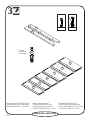
1
HAMMER
MARTEAU
MARTILLO
BLACK 2-1/4” FLAT HEAD SCREW - 6
VIS NOIRE TÊTE PLATE 57 mm - 6
TORNILLO NEGRO DE CABEZA PERDIDA de 57 mm - 6
KK
BLACK 1-7/8” FLAT HEAD SCREW - 3
VIS NOIRE TÊTE PLATE 48 mm - 3
TORNILLO NEGRO DE CABEZA PERDIDA de 48 mm - 3
LL
BLACK 1-1/8” MACHINE SCREW - 4
VIS NOIRE À MÉTAUX 28 mm - 4
TORNILLO NEGRO PARA METAL de 28 mm - 4
MM
SILVER 3/4” MACHINE SCREW - 16
VIS ARGENTÉE À MÉTAUX 19 mm - 16
TORNILLO PLATEADO PARA METAL de 19 mm - 16
NN
BLACK 9/16” FLAT HEAD SCREW - 4
VIS NOIRE TÊTE PLATE 14 mm - 4
TORNILLO NEGRO DE CABEZA PERDIDA de 14 mm - 4
OO
BROWN 7/16” LARGE HEAD SCREW - 6
VIS MARRON TÊTE LARGE 11 mm - 6
TORNILLO MARRÓN DE CABEZA GRANDE de 11 mm - 6
PP
GOLD 5/16” FLAT HEAD SCREW - 48
VIS DORÉE TÊTE PLATE 8 mm - 48
TORNILLO DORADO DE CABEZA PERDIDA de 8 mm - 48
QQ
NAIL - 71
CLOU - 71
CLAVO - 71
RR
ASSEMBLY TOOLS REQUIRED
OUTILS D’ASSEMBLAGE REQUIS
HERRAMIENTAS DE ENSAMBLAJE REQUERIDAS
TIP SHOWN ACTUAL SIZE
POINTE GRANDEUR NATURE
PUNTA MOSTRADA EN TAMAÑO REAL
NO. 2 PHILLIPS SCREWDRIVER
TOURNEVIS À TÊTE CRUCIFORME PHILLIPS n°2
DESTORNILLADOR PHILLIPS (CRUZ) No. 2
409937
BLACK 1-1/4” FLAT HEAD SCREW - 4
VIS NOIRE TÊTE PLATE 32 mm - 4
TORNILLO NEGRO DE CABEZA PERDIDA de 32 mm - 4
VV
BLACK 9/16” LARGE HEAD SCREW - 1
VIS NOIRE TÊTE LARGE 14 mm - 1
TORNILLO NEGRO DE CABEZA GRANDE de 14 mm - 1
XX
Adult Assembly Required
L’assemblage doit être effectué par un adulte
El ensamblaje debe hacerlo una persona adulta

www.sauder.com/services
2
Do
Do
not
not
tighten the HIDDEN CAMS in this step.
tighten the HIDDEN CAMS in this step.
Ne pas
Ne pas
serrer les EXCENTRIQUES ESCAMOTABLES à cette étape.
serrer les EXCENTRIQUES ESCAMOTABLES à cette étape.
No
No
apriete los EXCÉNTRICOS ESCONDIDOS en este paso.
apriete los EXCÉNTRICOS ESCONDIDOS en este paso.
(10 used)
(10 utilisées)
(10 utilizados)
Look for this icon. It means a video assembly tip is available at:
Repérer cette icône. Elle signifi e qu’un conseil de montage vidéo est disponible à :
Busque este icono. Signifi ca que un consejo práctico para ensamble de muebles, grabado en video, está disponible en:
www.sauder.com/services/tips
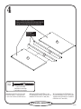
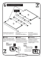
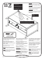
Assemble your unit on a carpeted
floor or on the empty carton to
avoid scratching your unit or
the floor.
Push twenty-two HIDDEN CAMS (AA2)
into the ENDS (A and B), UPRIGHT (C),
BOTTOMS (E), and DRAWER
BRACES (V). Then, insert ten CAM
DOWELS (CC2) into the HIDDEN CAMS.
Assembler l’élément sur un sol à
moquette ou sur le carton vide pour
éviter d’endommager l’élément ou le sol.
Enfoncer vingt-deux EXCENTRIQUES
ESCAMOTABLES (AA2) dans les
EXTRÉMITÉS (A et B), le MONTANT
(C), les DESSOUS (E) et les
ENTRETOISES DE TIROIR (V).
Insérer ensuite dix CHEVILLES
D’EXCENTRIQUE (CC2) dans les
EXCENTRIQUES ESCAMOTABLES.
Ensamble la unidad sobre un piso
alfombrado o sobre el cartón vacío para
evitar rayar la unidad o el piso.
Empuje veintidós EXCÉNTRICOS
ESCONDIDOS (AA2) dentro de los
EXTREMOS (A y B), del PARAL (C),
de los FONDOS (E) y de las RIOSTRAS
DE CAJÓN (V). A continuación,
inserte diez PASADORES DE
EXCÉNTRICO (CC2) dentro de los
EXCÉNTRICOS ESCONDIDOS.
Arrow
Flèche
Flecha
Arrow
Flèche
Flecha
Insert the CAM DOWEL into the HIDDEN CAM.
Insérer la CHEVILLE D’EXCENTRIQUE dans
l’EXCENTRIQUE ESCAMOTABLE.
Inserte el PASADOR DE EXCÉNTRICO dentro
del EXCÉNTRICO ESCONDIDO.
A
B
C
E
E
V
V
V
V
V
V
(22 used)
(22 utilisées)
(22 utilizados)
Do not insert CAM DOWELS into these parts.
Ne pas insérer les CHEVILLES D’EXCENTRIQUE dans ces pièces.
No inserte los PASADORES DE EXCÉNTRICO dentro de estas partes.
Do not insert CAM DOWELS into
these edges.
Ne pas insérer VIS D'EXCENTRIQUE
dans ces chants.
No inserte los PASADORES DE
EXCÉNTRICO dentro de estos bordes.
409937
Arrow
Flèche
Flecha
AA2
AA2
CC2

www.sauder.com/services
3
Turn twelve CAM SCREWS (BB2)
into the FRONT LEGS (G and H) and
DRAWER FRONTS (K, L, Q and R).
Faire tourner douze VIS
D'EXCENTRIQUE (BB2) dans
les PIEDS AVANT (G et H) et les
DEVANTS DE TIROIR (K, L, Q et R).
Atornille doce BIELAS DE
EXCÉNTRICO (BB2) dentro de las
PATAS DELANTERAS (G y H) y de las
CARAS DE CAJÓN (K, L, Q y R).
(12 used)
(12 utilisées)
(12 utilizados)
G
H
K
L
Q
Q
R
R
409937
BB2

www.sauder.com/services
4
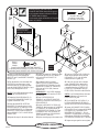
Fasten the REAR LEGS (I) to the
ENDS (A and B). Use six BLACK
2-1/4" FLAT HEAD SCREWS (KK).
Fixer les PIEDS ARRIÈRE (I) aux
EXTRÉMITÉS (A et B). Utiliser six VIS
NOIRES TÊTE PLATE 57 mm (KK).
Fije las PATAS POSTERIORES (I)
a los EXTREMOS (A y B). Utilice seis
TORNILLOS NEGROS DE CABEZA
PERDIDA de 57 mm (KK).
Black
Noire
Negro
6 used in this step
6 utilisées à cette étape
6 utilizados en este paso
KK
409937
A
I
B
I
Surface without HIDDEN CAMS
Surface sans EXCENTRIQUES ESCAMOTABLES
Superfi cie sin EXCÉNTRICOS ESCONDIDOS
Straight edge
Bord droit
Borde alineado

www.sauder.com/services
5
A
B
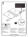
Turn four BLACK 9/16” FLAT
HEAD SCREWS (OO) into the
ENDS (A and B) until the shoulder of
the SCREWS rest on the surface of the
ENDS.
Slide the END
MOLDINGS (J) onto the
ENDS (A and B). Line up the
groove in the MOLDINGS over the
head of the SCREWS in the ENDS.
Faire tourner quatre VIS NOIRES
TÊTE PLATE 14 mm (OO) dans les
EXTRÉMITÉS (A et B) jusqu'à ce que
l'épaulement des TROUS repose sur la
surface des EXTRÉMITÉS.
Enfiler les MOULURES
D'EXTRÉMITÉ (J) sur les
EXTRÉMITÉS (A et B). Aligner la
rainure des MOULURES sur les têtes
des VIS dans les EXTRÉMITÉS.
Atornille cuatro TORNILLOS
NEGROS DE CABEZA PERDIDA de
14 mm (OO) dentro de los
EXTREMOS (A y B) hasta que el resalto
de los TORNILLOS repose sobre la
superficie de los EXTREMOS.
Deslice las MOLDURAS DE
EXTREMO (J) sobre los
EXTREMOS (A y B). Alinee la ranura
de las MOLDURAS sobre la cabeza de
los TORNILLOS de los EXTREMOS.
Black
Noire
Negro
4 used in this step
4 utilisées à cette étape
4 utilizados en este paso
OO
J
J
Apply pressure with your hands as you guide the
MOLDINGS over the SCREWS and onto the ENDS.
Avec les mains, appliquer une certaine pression
pour guider les MOULURES sur les VIS et sur les
EXTRÉMITÉS.
Con las manos, aplique presión sobre las
MOLDURAS mientras guía las MOLDURAS sobre
los TORNILLOS y los EXTREMOS.
Shoulder
Épaulement
Resalto
409937

www.sauder.com/services
6
Fasten the FRONT LEGS (G and H)
to the other surface of the ENDS (A
and B). Tighten six HIDDEN CAMS.
Fixer les PIEDS AVANT (G et H) sur
l'autre surface des
EXTRÉMITÉS (A et B). Serrer six
EXCENTRIQUES ESCAMOTABLES.
Fije las PATAS
DELANTERAS (G y H) a la otra
superficie de los EXTREMOS (A
y B). Apriete seis EXCÉNTRICOS
ESCONDIDOS.
409937
A
G
B
H
Surface with HIDDEN CAMS
Surface avec les EXCENTRIQUES ESCAMOTABLES
Superfi cie con EXCÉNTRICOS ESCONDIDOS
Curved edge
Chant arrondi
Borde redondeado
Caution
Risk of damage or injury. Hidden Cams
must be completely tightened. Hidden
Cams that are not completely tightened
may loosen, and parts may separate. Turn
the hidden cam 210 degrees to completely
tighten it.
Attention
Risque des dégâts ou blessures. Les
Excentriques Escamotables doivent
être serrés à bloc. Les Excentriques
Escamotables que ne sont pas serrées à
bloc peuvent desserrer et les pièces peuvent
séparer. Pour serrer à bloc, faire tourner
l'excentrique escamotable de 210 degrés.
Precaución
Riesgo de daños o heridas. Los
Excéntricos Escondidos deben apretarse
completamente. Los Excéntricos
Escondidos que no se aprieten
completamente se afl ojarán y las
partes pueden separarse. Para apretar
completamente, atornille el excéntrico
escondido 210 grados.
Tighten
Serrer
Apriete
Maximum 210 degrees
Maximum de 210 degrés
Máximo de 210 grados
Minimum 190 degrees
Minimum de 190 degrés
Mínimo de 190 grados
Arrow
Flèche
Flecha
Start
Commencer
Comience
Arrow
Flèche
Flecha

www.sauder.com/services
7
Fasten the CABINET
RIGHTS (40CA) and CABINET LEFTS
(40CB) to the ENDS (A and B) and
UPRIGHT (C). Use twenty-four GOLD
5/16" FLAT HEAD SCREWS (QQ).
Fixer les ÉLÉMENTS
DROITE (40CA) et les ÉLÉMENTS
GAUCHE (40CB) aux EXTRÉMITÉS
(A et B) et au MONTANT (C). Utiliser
vingt-quatre VIS DORÉES TÊTE
PLATE 8 mm (QQ).
Fije los GABINETES
DERECHO (40CA) y los GABINETES
IZQUIERDO (40CB) a los EXTREMOS
(A y B) y al PARAL (C). Utilice
veinticuatro TORNILLOS DORADOS DE
CABEZA PERDIDA de 8 mm (QQ).
C
Gold
Dorée
Dorado
24 used in this step
24 utilisées à cette étape
24 utilizados en este paso
QQ
Surface with HIDDEN CAMS
Surface avec les EXCENTRIQUES ESCAMOTABLES
Superfi cie con EXCÉNTRICOS ESCONDIDOS
Finished edge
Chant fi ni
Borde con acabado
Roller end
Extrémité à roulette
Extremo con rodillo
409937
A
Roller end
Extrémité à roulette
Extremo con rodillo
G
B
H

www.sauder.com/services
8
Fasten the LEFT END (B) and
UPRIGHT (C) to the TOP (D). Tighten
four HIDDEN CAMS.
Fixer l'EXTRÉMITÉ
GAUCHE (B) et le
MONTANT (C) au DESSUS (D).
Serrer quatre EXCENTRIQUES
ESCAMOTABLES.
Fije el EXTREMO
IZQUIERDO (B) y el PARAL (C) al
PANEL SUPERIOR (D). Apriete cuatro
EXCÉNTRICOS ESCONDIDOS.
B
C
D
Unfi nished surface
Surface non fi nie
Superfi cie sin acabado
H
Long fi nished edge
Long chant fi ni
Borde largo con acabado
Finished edge
Chant fi ni
Borde con acabado
409937
Maximum 210 degrees
Maximum de 210 degrés
Máximo de 210 grados
Minimum 190 degrees
Minimum de 190 degrés
Mínimo de 190 grados
Arrow
Flèche
Flecha

www.sauder.com/services
9
B
C
E
E
Insert four METAL PINS (GG) into
the BOTTOMS (E).
Insert the METAL PINS (GG) in one
end of the BOTTOMS (E) into the holes
in the LEFT END (B).
Fasten the BOTTOMS (E) to the
LEFT END (B). Tighten two HIDDEN
CAMS. Use a STRAIGHT EDGE
SCREWDRIVER.
Fasten the BOTTOMS (E) to the
UPRIGHT (C). Use two BLACK 1-7/8"
FLAT HEAD SCREWS (LL).
Insérer quatre GOUPILLES EN
MÉTAL (GG) dans les DESSOUS (E).
Enfoncer les GOUPILLES EN
MÉTAL (GG) située sur l'une extrémité
des DESSOUS (E) dans les trous dans
l'EXTRÉMITÉ GAUCHE (B).
Fixer les DESSOUS (E) à
l'EXTRÉMITÉ GAUCHE (B).
Serrer deux EXCENTRIQUES
ESCAMOTABLES. Utiliser un
TOURNEVIS À POINTE DROITE.
Fixer les DESSOUS (E) au
MONTANT (C). Utiliser deux VIS
NOIRES TÊTE PLATE 48 mm (LL).
Inserte cuatro ESPIGAS DE
METAL (GG) dentro de los FONDOS (E).
Inserte las ESPIGAS DE
METAL (GG) sujetada a un extremo de
los FONDOS (E) dentro de los agujeros
del EXTREMO IZQUIERDO (B).
Fije los FONDOS (E) al EXTREMO
IZQUIERDO (B). Apriete dos
EXCÉNTRICOS ESCONDIDOS.
Utilice un DESTORNILLADOR CON
PUNTA RECTA.
Fije los FONDOS (E) al PARAL (C).
Utilice dos TORNILLOS NEGROS DE
CABEZA PERDIDA de 48 mm (LL).
Arrow
Flèche
Flecha
210 degrees
210 degrés
210 grados
GG
Black
Noire
Negro
2 used in this step
2 utilisées à cette étape
2 utilizados en este paso
LL
Finished edge
Chant fi ni
Borde con acabado
Finished edge
Chant fi ni
Borde con acabado
409937
Surface with HIDDEN CAMS
Surface avec EXCENTRIQUES ESCAMOTABLES
Superfi cie con EXCÉNTRICOS ESCONDIDOS

www.sauder.com/services
10
Fasten the RIGHT END (A) to the
TOP (D) and BOTTOMS (E). Tighten
four HIDDEN CAMS.
NOTE: Be sure the METAL PINS in
the BOTTOMS insert into the holes in
the RIGHT END.
Fasten the BRACE (SS) and FOOT
BASE (UU) to the BOTTOM (E). Use four
BLACK 1-1/4” FLAT HEAD
SCREWS (VV) through the BASE,
through the BRACE, and into the
BOTTOM. Then, push the FOOT (TT)
into the FOOT BASE (UU).
NOTE: Turn the screw end of the
FOOT completely in. Adjustments will
be made to the FOOT after the unit is
standing upright.
Fixer l'EXTRÉMITÉ DROITE (A) au
DESSUS (D) et aux
DESSOUS (E). Serrer quatre
EXCENTRIQUES ESCAMOTABLES.
REMARQUE : S'assurer de bien insérer
les GOUPILLES EN MÉTAL situées
sur les DESSOUS dans les trous dans
l'EXTRÉMITÉ DROITE.
Fixer l’ENTRETOISE (SS) et la BASE
DE PIED (UU) au DESSOUS (E). Utiliser
quatre VIS NOIRES TÊTE PLATE 32
mm (VV) à travers la BASE, à travers
l’ENTRETOISE et dans le DESSOUS.
Enfoncer ensuite le PIED (TT) dans la
BASE DE PIED (UU)
.
REMARQUE :
Tourner l’extrémité
vis du PIED jusqu’à ce qu’il soit inséré
jusqu’au fond. Les ajustements au PIED se
feront une fois que l’unité sera à la verticale.
Fije el EXTREMO
DERECHO (A) al PANEL
SUPERIOR (D) y a los
FONDOS (E). Apriete cuatro
EXCÉNTRICOS ESCONDIDOS.
NOTA: Asegúrese de insertar las
ESPIGAS DE METAL de los FONDOS
dentro de los agujeros del EXTREMO
DERECHO.
Fije la RIOSTRA (SS) y la BASE DE
PATA (UU) al FONDO (E). Pase cuatro
TORNILLOS NEGROS DE CABEZA
PERDIDA de 32 mm (VV) a través de la
BASE, a través de la RIOSTRA y dentro
del FONDO. A continuación, introduzca la
PATA (TT) en la BASE DE PATA (UU).
NOTA:
Gire el extremo e inserte por
completo del tornillo de la PATA.
Se realizarán ajustes a la PATA después de
que la unidad esté en posición vertical.
E
E
A
D
G
409937
Black
Noire
Negro
4 used in this step
4 utilisées à cette étape
4 utilizados en este paso
VV
TT
UU
SS
Maximum 210 degrees
Maximum de 210 degrés
Máximo de 210 grados
Minimum 190 degrees
Minimum de 190 degrés
Mínimo de 190 grados
Arrow
Flèche
Flecha

www.sauder.com/services
11
Carefully turn your unit over onto its
front edges. Unfold the BACK (F) and
lay it over your unit.
Make equal margins along all four
edges of the BACK (F). Push on
opposite corners of your unit if needed to
make it “square”.
Fasten the BACK (F) to your unit
using the NAILS (RR).
NOTE:
Be sure to tap NAILS into the
holes that line up over the UPRIGHT (C).
NOTE: Perforations have been provided
for access through the BACK. Carefully
cut out the holes needed.
Avec précaution, retourner l’élément sur
ses chants avant. Déplier l’ARRIÈRE (F)
et le placer sur l’élément.
Veiller à avoir des marges égales le
long des quatre chants de
l’ARRIÈRE (F). Si besoin est, enfoncer
sur les coins opposés de l’élément pour
s’assurer d’être « d’équerre ».
Fixer l’ARRIÈRE (F) à l’élément en
utilisant les CLOUS (RR).
REMARQUE :
S'assurer de bien
enfoncer les CLOUS dans les trous qui
sont alignés au-dessus le MONTANT (C).
REMARQUE : Des lignes perforées ont
été prévues pour accéder facilement à
l’ARRIÈRE. Découper avec précaution
les trous nécessaires.
Cuidadosamente voltee la unidad para
que repose sobre los bordes delanteros.
Desdoble el DORSO (F) y colóquelo
sobre la unidad.
Fije el DORSO (F) de manera que los
márgenes son iguales a lo largo de los
cuatro bordes. Empuje sobre las esquinas
opuestas de la unidad si es requerido
para hacerla “cuadrada.”
Fije el DORSO (F) a la unidad
utilizando los CLAVOS (RR).
NOTA: Asegúrese de clavar ligeramente
los CLAVOS dentro de los agujeros que
se alinean sobre el PARAL (C).
NOTA: Hay perforaciones provistas
para el acceso a través del DORSO.
Cuidadosamente corte los agujeros
requeridos.
RR
47 used in this step
47 utilisés à cette étape
47 utilizados en este paso
Do not stand the unit upright without the
BACK fastened. The unit may collapse.
Ne pas relever l’élément dans sa position
verticale avant d’avoir fi xé l’ARRIÈRE.
L’élément risque de s’effondrer.
No coloque la unidad en posición vertical
hasta que se fi je el DORSO. La unidad
podría caerse.
Caution
Attention
Attention
Precaución
F
Cut-out
Découpe
Sección pre-recortada
409937
These holes must line up over
the UPRIGHT (C).
Ces trous doivent être alignés
au-dessus du MONTANT (C).
Estos agujeros deben alinearse
sobre el PARAL (C).
Printed information must be facing up.
Information imprimée doit être dirigée vers le haut.
La información impresa debe mirar hacia arriba.

www.sauder.com/services
12
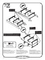
Insert the DRAWER SIDES (T
and U) at an angle into the slot at each end
of the RIGHT DRAWER FRONT (Q).
Slide the DRAWER BACK (S) into
the grooves in the DRAWER SIDES (T
and U) until the edge of the BACK is
even with the SIDES.
Repeat this step for the other drawers.
*U.S. Patent No. 6,413,007
Insérer les CÔTÉS DE TIROIR (T
et U) en biseau dans la fente dans chaque
extrémité du DEVANT DROIT DE
TIROIR (Q).
Enfiler l'ARRIÈRE DE
TIROIR (S) dans les rainures des
CÔTÉS DE TIROIR (T et U) jusqu'à ce
que le chant de l'ARRIÈRE soit à fleur
des CÔTÉS.
Répéter cette étape pour les autres
tiroirs.
* Brevet État Unis n° 6.413.007
Inserte los LADOS DE CAJÓN (T
y U) en ángulo dentro del encaje en cada
extremo de la CARA DERECHA DE
CAJÓN (Q).
Deslice el DORSO DE CAJÓN (S)
dentro de las ranuras de los LADOS DE
CAJÓN (T y U) hasta que el borde del
DORSO esté nivelado con los LADOS.
Repita este paso para los otros
cajones.
* No. de Pantente EE.UU. 6,413,007
These edges should be even.
Ces chants devraient être à fl eur.
Estos bordes deben estar nivelados.
The tabs should insert freely into the slots. Gently tilt the
DRAWER SIDES side to side until the tabs slip into the slots.
Les pattes devraient s’insérer librement dans les fentes.
Légèrement incliner les CÔTÉS DE TIROIR d’un côté vers
l’autre jusqu’à ce que les pattes s’enfi lent dans les fentes.
Las lengüetas deben insertarse sin problemas dentro de los
encajes. Ligeramente incline los LADOS DE CAJÓN de un lado
al otro hasta que las lengüetas se deslicen dentro de los encajes.
Groove
Rainure
Ranura
Groove
Rainure
Ranura
1
st
2
nd
Q
T
U
T
U
S
409937

www.sauder.com/services
13
Slide a DRAWER BOTTOM (P)
into the grooves in the DRAWER
SIDES (T and U) and RIGHT DRAWER
FRONT (Q).
Flip the drawer over and insert four
CLIPS (DD) into the groove in the
DRAWER BACK (S) and wrap them
over the DRAWER BOTTOM (P). Tap a
NAIL (RR) through each CLIP.
NOTE: The CLIPS should set in about
1” from the DRAWER SIDES.
Fasten the DRAWER BRACE (V)
to the RIGHT DRAWER FRONT (Q).
Tighten a HIDDEN CAM.
Insert the DRAWER BOTTOM
BRACKET (II) into the groove in the
DRAWER BACK (S) and wrap it over
the DRAWER BRACE (V). Fasten the
BRACKET to the DRAWER BRACE
using a BROWN 7/16" LARGE HEAD
SCREW (PP).
Repeat this step for the other drawers.
Enfiler un FOND DE TIROIR (P) dans
les rainures des CÔTÉS DE TIROIR (T
et U) et du DEVANT DROIT DE
TIROIR (Q).
Retourner le tiroir et insérer
quatre CLIPS (DD) dans la rainure
de l'ARRIÈRE DE TIROIR (S) et les
enrober sur le FOND DE TIROIR (P).
Enfoncer un CLOU (RR) à travers
chaque CLIP.
REMARQUE : Les CLIPS devraient
être situés environ 25 mm des CÔTÉS
DE TIROIR.
Fixer l’ENTRETOISE DE
TIROIR (V) au DEVANT DROIT DE
TIROIR (Q). Serrer un EXCENTRIQUE
ESCAMOTABLE.
Insérer la CONSOLE DE FOND DE
TIROIR (II) dans la rainure de l’ARRIÈRE
DE TIROIR (S) et l’enrober autour de
l’ENTRETOISE DE TIROIR (V). Fixer
la CONSOLE sur l’ENTRETOISE DE
TIROIR à l’aide d’une VIS MARRON
TÊTE LARGE 11 mm (PP).
Répéter cette étape pour les autres tiroirs.
Deslice el FONDO DE CAJÓN (P)
dentro de las ranuras de los LADOS
DE CAJÓN (T y U) y de la CARA
DERECHA DE CAJÓN (Q).
Vuelva el cajón al revés e inserte
cuatro GRAPAS (DD) dentro de la
ranura del DORSO DE CAJÓN (S)
y envuélvalas sobre el FONDO DE
CAJÓN (P). Ligeramente clave un
CLAVO (RR) a través de cada GRAPA.
NOTA: Las GRAPAS deben colocarse
aproximadamente a 25 mm de los
LADOS DEL CAJÓN.
Fije la RIOSTRA DE CAJÓN (V) a
la CARA DERECHA DE CAJÓN (Q).
Apriete un EXCÉNTRICO ESCONDIDO.
Inserte el SOPORTE DEL FONDO
DE CAJÓN (II) en la ranura del DORSO
DE CAJÓN (S) y envuélvalo en la
RIOSTRA DE CAJÓN (V). Fije el
SOPORTE a la RIOSTRA DE CAJÓN
utilizando un TORNILLO MARRÓN
DE CABEZA GRANDE de 11 mm (PP).
Repita este paso para los otros cajones.
With the palm of your hand, tap the
DRAWER BOTTOM down into the groove.
Avec la paume de main, enfoncer le FOND
DE TIROIR dans la rainure.
Con la mano, golpee el FONDO DE CAJÓN
dentro de la ranura.
Unfi nished surface
Surface non fi nie
Superfi cie sin acabado
1
st
Groove
Rainure
Ranura
2
nd
24 used in this step
24 utilisés à cette étape
24 utilizados en este paso
RR
Brown
Marron
Marrón
6 used for the DRAWER BOTTOM BRACKET
6 utilisées pour la CONSOLE DE FOND DE TIROIR
6 utilizados para el SOPORTE DEL FONDO DE CAJÓN
PP
DD
RR
II
Q
T
U
S
P
T
Q
P
V
409937

www.sauder.com/services
14
Insert a SLIDE CAM (HH) into the
DRAWER SIDES (T and U).
Fasten the DRAWER RIGHT (40CC)
and DRAWER LEFT (40CD) to the
DRAWER SIDES (T and U). Use four
GOLD 5/16” FLAT HEAD
SCREWS (QQ).
NOTE: The screw head in the CAM
must be visible through the slotted hole
in the SLIDE.
Repeat this step for the other drawers.
Insérer un EXCENTRIQUE DE
COULISSE (HH) dans les CÔTÉS DE
TIROIR (T et U).
Fixer le TIROIR DROITE (40CC) et le
TIROIR GAUCHE (40CD) aux CÔTÉS
DE TIROIR (T et U). Utiliser quatre VIS
DORÉES TÊTE PLATE 8 mm (QQ).
REMARQUE : La tête de vis dans
l’EXCENTRIQUE doit être visible à
travers le trou fendu dans la COULISSE.
Répéter cette étape pour les autres tiroirs.
Inserte un EXCÉNTRICO DE
CORREDERA (HH) dentro de los
LADOS DE CAJÓN (T y U).
Fije el CAJÓN DERECHO (40CC) y
el CAJÓN IZQUIERDO (40CD) (Y y Z)
a los LADOS DE CAJÓN (T y U). Utilice
cuatro TORNILLOS DORADOS DE
CABEZA PERDIDA de 8 mm (QQ).
NOTA: La cabeza de tornillo del
EXCÉNTRICO debe ser visible a través
del agujero alargado de la
CORREDERA.
Repita este paso para los otros cajones.
Gold
Dorée
Dorado
24 used in this step
24 utilisées à cette étape
24 utilizados en este paso
QQ
HH
Roller end
Extrémité à roulette
Extremo con rodillo
Roller end
Extrémité à roulette
Extremo con rodillo
T
U
409937
Screw head -- turn CAM to line up holes in
SLIDES with holes in DRAWER SIDES.
Tête de vis -- faire tourner l’EXCENTRIQUE
pour aligner les trous des COULISSES sur les
trous des CÔTÉS DE TIROIR.
Cabeza de tornillo -- gire el EXCÉNTRICO
para alinear los agujeros de las CORREDERAS
con los agujeros de los LADOS DE CAJÓN.

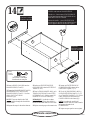
www.sauder.com/services
15
Fasten the KNOBS (FF) to the
SMALL RIGHT DRAWER FRONT (K).
Use two BLACK 1-1/8" MACHINE
SCREWS (MM).
NOTE: Repeat this step for the other
small drawer.
Fasten the PULLS (EE) to the RIGHT
DRAWER FRONT (Q). Use four
SILVER 3/4" MACHINE
SCREWS (NN).
NOTE: Repeat this step for the other
drawers.
Fixer les BOUTONS (FF) au DEVANT
DROIT DE PETIT TIROIR (K). Utiliser
deux VIS NOIRES À MÉTAUX
28 mm (MM).
REMARQUE : Répéter cette étape
pour l'autre petit tiroir.
Fixer les POIGNÉES (EE) au
DEVANT DROIT DE TIROIR (Q).
Utiliser quatre VIS ARGENTÉES À
MÉTAUX 19 mm (NN).
REMARQUE : Répéter cette étape
pour les autres tiroirs.
Fije las MANILLAS (FF) a la CARA
DERECHA DE CAJÓN PEQUEÑO (K).
Utilice dos TORNILLOS NEGROS PARA
METAL de 28 mm (MM).
NOTA: Repita este paso para el otro
cajón pequeño.
Fije los TIRADORES (EE) a la
CARA DERECHA DE
CAJÓN (Q). Utilice cuatro TORNILLOS
PLATEADOS PARA METAL de
19 mm (NN).
NOTA: Repita este paso para los otros
cajones.
MM
Black
Noire
Negro
4 used for the Small Drawers
4 utilisées pour les Petits Tiroirs
4 utilizados para los Cajones Pequeños
Silver
Argentée
Plateado
16 used in this step
16 utilisées à cette étape
16 utilizados en este paso
NN
K
Q
EE
FF
409937

www.sauder.com/services
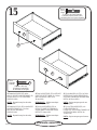
16
409937
20 lbs.
9 kg
20 lbs.
9 kg
Carefully stand your unit upright.
To insert the drawers into your unit,
tip the front of the drawer down and
drop the rollers on the drawer behind the
rollers on the unit. Lift the front of the
drawer up and slide it into the unit.
Apply the WARNING
LABEL (JJ) to the upper LEFT
DRAWER SIDE (O). You should
be able to read the label when the
drawer is open. When the drawer is
closed, it will hide the label. Peel
off the backing and apply the label
as shown in the diagram.
NOTE: This is a permanent label
intended to last for the life of the
product. Once applied, do not try
to remove it.
Avec précaution, placer l'élément dans
sa position verticale.
Pour insérer les tiroirs dans l’élément,
abaisser le devant du tiroir et faire passer
les roulettes situées sur le tiroir derrière les
roulettes situées sur l’élément. Relever le
devant du tiroir et l’enfiler dans l’élément.
Apposer l’ÉTIQUETTE DE MISE EN
GARDE (JJ) sur le CÔTÉ GAUCHE
DE TIROIR SUPÉRIEUR (O). Cette
étiquette doit pouvoir être lisible lorsque
le tiroir est ouvert. Lorsque le tiroir est
fermé, il doit la dissimuler. Décoller le
film protecteur et apposer l’étiquette
comme l’indique le schéma.
REMARQUE : Cette étiquette
permanente est prévue pour durer
pendant toute la vie du produit. Une fois
apposée ne pas essayer de la retirer.
Cuidadosamente ponga la unidad en
posición vertical.
Para insertar los cajones dentro de la
unidad, incline la parte delantera del
cajón hacia abajo y deje que los rodillos
del cajón caigan detrás de los rodillos de
la unidad. Levante la parte delantera del
cajón y deslícelo dentro de la unidad.
Aplique la ETIQUETA DE
ADVERTENCIA (JJ) al LADO
IZQUIERDO DE CAJÓN SUPERIOR (O).
Usted debe poder leer la etiqueta cuando
el cajón está abierto. Cuando el cajón está
cerrado, éste ocultará la etiqueta. Quite el
material protector y aplique la etiqueta tal
como se muestra en el diagrama.
NOTA:
Esta etiqueta es permanente e
intencionada a durar por la vida del producto.
Una vez aplicada, no intente quitarla.
40 lbs.
18 kg
35 lbs. each
15 kgs chaque
15 kg cada
JJ
Q
Q
R
K
L
R
O
WARNING
Serious or fatal crushing injuries can
occur from furniture tip-over. To help
prevent tip-over:
-Place heaviest items in the lowest drawers.
-Unless specifi cally designed to
accommodate, do not set TVs or other heavy
objects on top of this product.
-Never allow children to climb or hang on
drawers, doors, or shelves.
-Never open more than one drawer at a time.
-If equipped with a drawer interlock system,
do not defeat or remove it.
Use of tip-over restraints may only reduce,
but not eliminate, the risk of tip-over.

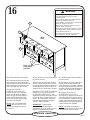
www.sauder.com/services
17
409937
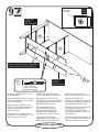
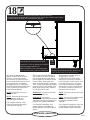
We recommend using the SAFETY
BRACKET (WW) for added stability.
Use a BLACK 9/16” LARGE HEAD
SCREW (XX) into the top of the unit
and a BLACK 1-7/8” FLAT HEAD
SCREW (LL) into a stud in your wall.
Il est recommandé d'utiliser la
CONSOLE DE SÉCURITÉ (WW) pour
renforcer la stabilité. Utiliser une VIS
NOIRE TÊTE LARGE 14 mm (XX)
dans le haut de l'élément et une VIS
NOIRE TÊTE PLATE 48 mm (LL) dans
un montant du mur.
Se recomienda que utilice la MÉNSULA
DE SEGURIDAD (WW) para aumentar
la estabilidad. Utilice un TORNILLO
NEGRO DE CABEZA GRANDE de
14 mm (XX) a través de la parte superior
de la unidad y un TORNILLO NEGRO DE
CABEZA PERDIDA de 48 mm (LL) dentro
de un montante de la pared.
Black
Noire
Negro
1 used into a stud in your wall
1 utilisée dans un poteau mural
1 utilizado en un montante de la pared
LL
XX
Black
Noire
Negro
1 used for the SAFETY BRACKET
1 utilisée pour la CONSOLE DE SÉCURITÉ
1 utilizado para la MÉNSULA DE SEGURIDAD
WW
La page est en cours de chargement...
La page est en cours de chargement...
La page est en cours de chargement...
La page est en cours de chargement...
-
 1
1
-
 2
2
-
 3
3
-
 4
4
-
 5
5
-
 6
6
-
 7
7
-
 8
8
-
 9
9
-
 10
10
-
 11
11
-
 12
12
-
 13
13
-
 14
14
-
 15
15
-
 16
16
-
 17
17
-
 18
18
-
 19
19
-
 20
20
-
 21
21
-
 22
22
-
 23
23
-
 24
24


Sauder 409937 Assembly Instructions Manual
- Taper
- Assembly Instructions Manual
dans d''autres langues
- English: Sauder 409937
- español: Sauder 409937
Documents connexes
-
Sauder 409942 Assembly Instructions Manual
-
-
-
-
-
-
-
-
-
