GE ZV42ISH1SS Guide d'installation
- Catégorie
- Hottes
- Taper
- Guide d'installation
Ce manuel convient également à

installation
®
Instr ct
Island Vent Hoods
Models:
ZV421
ZV541

SafetyInformation
READ AND SAVE THESE INSTRUCTIONS
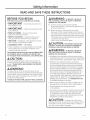
BEFORE YOU BEGIN
Read these instructions completelg and carefullg.
"IMPORTANT- Savetheseinstructionsfor
local inspector's use.
"IMPORTANT- Observeallgoverningcodes
and ordinances.
. Note to Installer - Besure to leave these
instructions with the Consumer.
. Note to Consumer - Keepthese instructions
with gour Owner's Manual for future reference.
* Skill Level -Installation of this appliance requires
basic mechanical and electrical skills.
. Completion Time - i to 3 Hours.
. Proper installation isthe responsibilitg of the installer.
Product failure due to improper installation is not
covered under the warrantg.
ForMonogram localservicein gour area,call 1.800.4443845.
For Monogram service in Canada, call 1.800.561.3344.
For Monogram Parts and Accessories, call 1.800.626.2002.
CAUTION:
Due to the weight and size of these vent hoods and
to reduce the risk of personal injurg or damage to the
product, THREEPEOPLEAREREQUIREDFORPROPER
INSTALLATION.
AWARNING:
To reducetheriskoffireorelectricalshock,do not
usethisrangehoodwithang externalsolid-statespeed
control device. Any such alteration from original factorg
wiring could result in damage to the unit and/or create
an electrical safetg hazard.
TO REDUCETHERISKOFFIRE,USEONLYMETALDUCTWORK.
WARNING: To REDUCE THE RISK OF
FIRE, ELECTRICAL SHOCK OR INJURY TO PERSONS,
OBSERVE THE FOLLOWING:
A. Use this unit onlg in the manner intended
bg the manufacturer. If gou hove ang questions, con-
tact the manufacturer.
B.
Before servicing or cleaning the unit, switch
the power off at the service panel and lock the ser-
vice disconnecting means to prevent the power from
being switched on accidentallg. When the service dis-
connecting means cannot belocked, securelg fasten
a prominent warning device,
such as a tag, to the service panel.
ACAUTION: FORGENERALVENTILATING
USE ONLY. DO NOT USE TO E×HAUST HAZARDOUS
MATERIALS,E×PLOSIVEMATERIALSOR VAPORS.
AWARNING: TO REDUCE THE RISK OF
FIRE, ELECTRICAL SHOCK OR INJURY TO PERSONS,
OBSERVE THE FOLLOWING:
. Installation work and electrical wiring must be done
bg qualified person(s)in accordance with all applicable
codes and standards, including fire-rated construction.
* Sufficient air is needed for proper combustion
and exhausting of gases through the flue (chimneg)
of fuel burning equipment to prevent back-drafting.
Follow the heating equipment manufacturer's guide-
lines and safetg standards, such as those published
bg the National Fire Protection Association (NFPA),
the American Societg for Heating, Refrigeration and
Air Conditioning Engineers (ASHRAE)and the local
code authorities. When applicable, install any makeup
(replacement) air system in accordance with local
building code requirements. Visit GEAppliances.com
for available makeup air solutions,
* When cutting or drilling into walls or ceilings, do not
damage electrical wiring and other hidden utilities.
* Ducted systems must always be vented
to the outdoors.
Local codes vary. Installation of electrical connections
and grounding must comply with applicable codes.
In the absence of local codes, the vent should be
installed in accordance with National Electrical Code
ANSI/NFPA70-1990 or latest edition.
A CAUTION: TOreduceriskoffireand to
properlyexhaustair,be suretoductairoutside-donot
ventexhaustairintospaceswithinwallsorceilingsor
intoattics,crawlspacesorgarages.
49 80209 5

Consignes de S@curit_
LISEZ ETCONSERVEZ
AVANT DE COMMENCER
Lisez ces instructions enti_rement et attentivement.
"IMPORTANT- Conservezces instructions
pour I'inspecteur 61ectrique local.
" IMPORTANT- Respecteztouslescodeset
r_glementsen vigueur.
. Remarque pour I'installateur - Assurez-vous
de remettre ces instructions 5 I'utilisateur.
@
@
Remarque pour I'Utilisateur - Conservez ces
instructions avec votre notice d'utilisation pour toute
r6f@ence future.
Niveau de comp@tence - L'installation de cet
appareil demande des connaissances de base en
m6canique et en 61ectricit_.
D@lai d'ex@cution - 1 6 3 heures.
L'installateur est responsable de I'installation
correcte de I'appareil. La panne de I'appareil due a
une mauvaise installation n'est pas couverte par la
garantie.
Pour les services Ioceux Monogram dans votre secteur,
appelez le 1.800.444.1845.
Pour lesservicesMonogram au Canada, appelezle
1.800.561.3344.
Pour les Pi_ces et Accessoires Monogram, appelez
1.800.626.2002.
_,MISE EN GARDE :
A cause de la taille et du poids de ces hottes d'extraction
ainsi que pour r_duire le risque de blessure corporelle
ou de dommage au produit, TROISPERSONNESSONT
REQUISESPOURUNE INSTALLATIONCORRECTE.
_AVERTISSEMENT :
Pour r6duire le risque d'incendie ou de choc 61ectrique,
n'utilisez pas cette hotte avec un dispositif de contr61e
de la vitesse 5 semi-conducteurs. Toute alt@ation du
c(3blage61ectrique d'origine peut endommager I'appareil
et/ou cr6er un risque 61ectrique.
POURREDUIRELERISQUED'INCENDIE,N'UTILISEZQUEDES
CONDUITSMErALLIQUES.
ZkAVERTISSEMENT: POURR_DU,RE
LE RISQUED'INCENDIE, DE CHOCELECTRIQUEOU DE
BLESSURECORPORELLE,SUIVEZLESINSTRUCTIONS
SUIVANTES:
A. Cet appareil doit uniquement _tre utilis6 aux fins
pr6vues par le fabricant. Si vous avez des questions,
contactez le fabricant.
CES INSTRUCTIONS
B.
Avant de r6parer ou de nettoger un appareil, coupez
I'alimentation 61ectrique au niveau du tableau de
distribution et verrouillez le disjoncteur pour _viter
que I'alimentation 61ectrique ne soit accidentellement
r6tablie. Quand il n'est pas possible de verrouiller le
disjoncteur, attachez un moLlen d'avertissement, une
@iquette par exemple, au panneau de distribution.
A M ISE EN GA RD E :UNIQUEMENT
POUR UNE I:VACUATIONDE TYPE GI:NI_RALN'UTILISEZ
PAS CET APPAREILPOUR F!VACUERDES SUBSTANCES
OU DES VAPEURS NOCIVES OU EXPLOSIVES.
AAVERTISSEMENT : POURR_DU,RE
LERISQUED'INCENDIE, DECHOC I_LECTRIQUEOU DE
BLESSURECORPORELLE,SUIVEZLESINSTRUCTIONS
SUIVANTES:
. L'installation et le c(3blage61ectrique doivent _tre
effectu6s par une ou plusieurs personnes qualifi6es,
conform6ment (3tousles codes et toutes les normes
applicables, dont ceux concernant la r6sistance au feu
des constructions.
, Une quantit6 d'air suffisante est n6cessaire (3une
combustion et une _vacuation appropri6es des
gaz par le conduit d'_vacuation (chemin_e) de
1'6quipement (3combustible pour 6viter tout refoule-
ment. Suivez les directives et normes de s6curit6 du
fabricant de I'appareil chauffant, comme celles pub-
li6es par la National Fire Protection Association (NFPA),
par I'American Societg for Heating, Refrigeration and
Air Conditioning Engineers (ASHRAE)et par les auto-
rit6s locales. Le cos 6ch6ant, installez un sgst_me de
compensation d'air (remplacement) conform_ment
aux conditions des codes Iocaux du b(3timent. Visitez
le site GEApplionces.com pour connaTtre les solutions
offertes en mati@e de sLIst_me de compensation d'air.
, Lorsque vous effectuez des d6coupes ou que vous
percez un mur ou un plafond, n'endommagez pas le
c(3blage61ectrique ou tout autre r6seau d'alimentation
cach&
L'air des ventilateurs disposant de conduits d'a@ation
doit toujours @tre6vacu6 vers I'ext@ieur.
Les codes Iocaux peuvent varier. L'installation de
branchements 61ectriques et la mise (3la terre doivent
@treconformes aux codes en vigueur. Les6vacuations
doivent @treinstall6es conform@ment (3la derni@re@di-
tion du Code Electrique National ANSI/NFPANo
70-1990.
_,MISE EN GARDE :Pourr@duire
le risque d'incendie et @vacuercorrectement l'air en
I'@vacuantvers I'ext@ieur-n'@vacuez pas I'air vers un
espace entre deux murs ou dans le plafond ou encore
dans un grenier, un vide sanitaire ou un garage.
49 80209 5 3

Design Information
CONTENTS
Design Information
Product Dimensions ............................................................................4
Duct Cover Accessories .....................................................................5
Product Clearances .............................................................................5
Advance Planning
Ductwork Planning .............................................................................6
Ceiling Framing for Support ............................................................6
Accessorg Frames and Duct Covers .........................................6
Mounting the hood without a support frame .......................6
Power Supplg ........................................................................................6
Installation Height ...............................................................................7
Duct Fittings ..........................................................................................8
Installation Preparation
Tools and Materials Required.........................................................9
Remove the Packaging ....................................................................9
Parts, Hardware, Accessorg Packages .................................10
Installation Instructions
Step !, Construct Ceiling Support .....................................11-13
Step
Step
Step
Step
Step
Step
Step
Step
Step
Step
Step
Step
Step
Step
2, Mount Template .................................................................14
3, Sizeand Install Ductwork ..............................................14
4, Install Support Frame and Duct Covers.................15
5, Install Duct Transition and Damper ........................16
6, Install Hood to Support...................................................16
7, Connect Duct ......................................................................16
8, Connect Electrical..............................................................17
9, Install the Motor .................................................................17
10,Slide Duct Cover Down ................................................18
11,Install Filters.......................................................................18
12,Install Rods.........................................................................18
13,Install Supplied Duct Cover, Top Cover................19
14,Finalize Installation .........................................................19
15,Installation Checklist ....................................................19
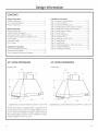
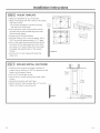
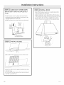
42" HOOD DIMENSIONS 54" HOOD DIMENSIONS
Model ZV421
20"
14"
Supplied duct covers dimensions: 16"W x 12"D x 9"H
These vent hoods are supplied with a support frame
and decorative duct cover for ceiling heights of 7'11"
to 8'5". The hood installation height is determined bg
the ceiling height. Accessories are available to reach
ceiling heights from 8'6" to 10'4".
Model ZV541
16"
......[............... 33" •.....
/
24"
_36-1/4"_ _ ....... 54 ......................
/
Supplied duct covers dimensions: 20-1/4"W x 12"D x 5"H
49 80209 5

Design Information
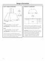
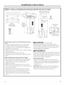
DUCT COVER ACCESSORIES
_]_ *Height
to Ceiling
_L_3
20" F0!ZV42I
ForZV54I
ZV421
* 9" for ceiling heights 7'11" to 8'5" using the
supplied support frame and duct cover.
Order ZX42DC10 for ceiling heights of 8"6" to 10'4".
ZV541
* 5" for ceiling heights 7'11" to 8'5" using the
supplied support frame and duct cover.
Order ZX54DC10 for ceiling heights of 8"6" to 10'4".
These accessories include telescoping support
frames and decorative covers. Order the accessory
for your model at the same time as the vent hood
and have on site before installation begins.
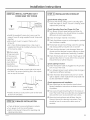
PRODUCT CLEARANCES
[
o
36" Min.
o
o
o
These vent hoods must be installed 30" min. to 36"
max. above the cooking surface. Exact installation
height is determined by ceiling height. The cooking
surface should be at least 36" above the floor.
IMPORTANT: Clearances may vary due to type of
cooking product and local codes. Check with local
inspectors to be sure standard is applicable.
, When installing these Island Hoods above a
Monogram Professional Range or Cooktop,
installation clearance must be at least 30".
Z_9 80209 5 5

Advance Planning
ADVANCE PLANNING
Ductwork Planning
,These vent hoods are equipped for 10" round
ductwork.
, Determine the exact location of the vent hood.
, Plan the route for venting exhaust to the outdoors.
, Use the shortest and straightest duct route
possible. For sotisfoctorg performance, duct run
should not exceed 150 ft. equivalent length for ang
duct configurations.
, Refer to "Duct Fittings" chart to compute the
maximum permissible length for duct runs to the
outdoors.
, Use rigid metal ductwork onlg.
, Install o roof cop with damper at the exterior
opening. Order the cop and ang transitions needed
in advance.
,When applicable, install ong makeup (replacement)
air sgstem in accordance with local building code
requirements. Visit GEAppliances.com for available
makeup air solutions.
Ceiling Framing for Adequate Support
,These vent hoods are heavg. Adequate structural
support must be provided. The ceiling structure
must be capable of supporting the weight of the
hood and ong inadvertent user contact loads
(approximatelg 300 pounds). The hood support
frame will be supported bg 2 x 4 cross framing.
Accessorg Frames and Duct Covers
,All models ere shipped with a support frame and
duct covers for ceilings heights of 7'11" to 8'5".
,Optional accessories include telescoping support
frames and duct covers to reach 8'6" and up to
10'4" ceiling heights.
,Optional accessories must be ordered with the
hood and be on site before final framing and wall
finishing.
Mounting the hood without a support frame
The distance between the cooking surface and the
bottom of the hood must be 30" to 36". In situations
where the ceiling is low, the hoods meg be secured
directlg to the ceiling without the supplied frame.
Use the bottom of the supplied support frame as
a template to locate the mounting holes in the top
of the hood. Use shims on the ceiling joists or cross
framing in the mounting hole locations. This will
allow the mounting screws to engage the recessed
keghole slots in the top of the hood. See Step 2.
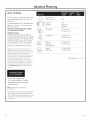
POWER SUPPLY
IMPORTANT - (Please read carefully)
-&WARNING:
FOR PERSONAL SAFETY,THIS APPLIANCE MUST BE
PROPERLYGROUNDED.
AATTENTION - POURDES
RAISONS DE SECURITE,CET APPAREIL DOIT ETRE
CORRECTEMENT MIS A LA TERRE
Remove house fuse or open circuit breaker before
beginning installation.
Do not use an extension cord or adapter plug with
this appliance. Follow National Electrical Code or
prevailing local codes and ordinances.
Electrical Supplg
This vent hood must be supplied with 120V, 60Hz,
and connected to an individual, properlg grounded
branch circuit, and protected bg a 15 or 20 amp
circuit breaker or time delag fuse.
, Wiring must be 2 wire with ground.
, If the electrical supplg does not meet the above
requirements, call a licensed electrician before
proceeding.
, Route house wiring in the ceiling, as close to the
installation location as possible. Allow additional
length from ceiling joists to reach the junction box
on the bottom of the hood support frame.
, Connect the wiring to the house wiring in
accordance with local codes.
Grounding Instructions
The grounding conductor must be connected to
a ground metal, permanent wiring sgstem, or an
equipment-grounding terminal or lead on the hood.
AWARN ING: The improper connectionof
equipment-grounding conductor can result in a risk
of electric shock. Check with a qualified electrician
or service representative if gou are in doubt
whether the appliance is properlg grounded.
AAVERTISSEMENT
Le mauvais branchement du fil de mise (_la terre
peut causer un choc 61ectrique. En cas de doute,
consulter un 61ectricien qualifi6 ou un technicien
pour d6terminer si I'appareil est (_la terre.
49 80209 5

Advance Planning
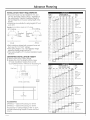
INSTALLATIONHEIGHTREQUIREMENTS
• Thesevent hoods must be installed 30" min. and
36" max. above the cooking surface - regardless of
the ceiling height. Therefore, installation height of
the hood depends on the exact ceiling height of the
kitchen.
• Accessories are available for ceiling heights 8'6" and
up to 10'4".
Example: Hood installation height with 8 ft. ceilings.
8 ft. Ceiling 8 ft. Ceiling
9" s" II II
Supplied Supplied/
Duct Duct {_= ,,,,,_
Cover Cover t -
31" 31"
i
ZV421 ZV541
• Bothmodelsare shippedwith a supportframe and
ductcoverfor 7'11"to 8'5"ceilings.
• Ifthe ceilingheightis7'1r', the installationheight
abovethe cookingsurfacewillbe30".
• Ifthe ceiling height is8'5%the hood installation height
will be 36".
DETERMINE INSTALLATION HEIGHT
1. Heasure the exact ceiling height.
2. Review the chart to determine the range
of hood installation heights that can be
accomplished with or without an accessorg kit.
Duct Cover t _i_ ....
,'"" L 20"forZV42I'"',,
/" / 24" for ZV54I ",,,
30" Min. and 36"Max.
II II
3@"
to
Countertop
Ceiling
Heicht
ACCESSORIES
ZX42DC10 - Optional Accessory for ZV421.
ZX54DC10 - Optional Accessory for ZV541.
Accessories for ceiling heights of 8'6" to 10'4".
Includes telescoping support frames and duct
cove rs.
Actual Chimney Length at
Ceiling Hood Insta!tgtion H_igh!
Height 30" 3r' 32 33 | 34' 35
10'4" 36 35 34 33
10'3" 36 35 34 33 32
I
10'2" 36 35 34 33 32 31
iO'i" 35 34 33 32 31 30
10' 34 33 32 31 30 29
9'11" 33 32 31 30 29 28
9'10" 32 31 30 29 28 27
9'9" 31 30 29 28 27 26
9'8" 30 29 28 27 26 25
9'7" 29 28 27 26 25 24
9'6" 28 27 26 25 24 23
9'5" 27 26 25 24 23 22
9'4" 26 25 24 23 22 21
I
9'3" 25 24 23 22 21 20
9'2" 24 23 22 21 20 19
9'1" 23 22 21 20 19 18
I
9' 22 21 20 19 18 17
8'11" 21 20 19 18 17 16
8'10" 20 19 18 17 16 15
8'9" 19 18 17 16 15
8'8" 18 17 16 15
8'7" 17 16 15
8'6" 16 15
8'5" 15
8'4" 9
8'3" 9
8'2" 9
8'1" 9
8' 9
7'11" 9
Duct
Cover
36" Kit
32
31 Order
30 ZX42DC10
29 Use Long
28 Support
27 and
26 Duct Cover
25
24
23
22
21 Order
20 ZX42DCI0
19 Use Short
18 Support
17 and
16 Duct Cover
15
I
2
Use
Supplied
Support
and
Duct Cover
_,ctuat Chimney Length at Duct
:eiling Hood Insta,!tationHeight Cover
30" 3r' 32" 33 34' 35 J36" KitHeight
10'4" 28
10'3" 28 27 Order
10'2" 28 27 26 ZXS4DClO
10'1" 28 27 26 25 Use Long
10' 28 27 26 25 24 Support
9'lr' 28 27 26 25 24 23 and
9'10" 28 27 26 25 24 23 22 Duct Cover
9'9" 27 26 25 24 23 22 21
9'8" 26 25 24 23 22 21 20
9'7" 25 24 23 22 21 20 19
9'6" 24 23 22 21 20 19 18
9'5" 23 22 21 20 19 18 17
9'4" 22 21 20 19 18 17 16 Order
9'3" 21 20 19 18 17 16 15 ZX54DC10
9'2" 20 19 18 17 16 15 14 Use Short
9'2" 29 28 27 16 15 14 13 Support
9' 18 17 16 15 14 13 12 and
B'I 2" 27 26 25 24 23 22 Duct Cover
B'IO" 16 15 14 13 12
B'9" 15 14 13 12
I
B'8" 14 13 12
B'7" 13 12
B'6" 12
B'5" 5 Use
9'4" 5 Supplied
B3" 5 Support
B'2" 5_ and
B'2" 5 Duct Cover
9' 5
7'11" i 5
49 80209 S 7

Advance Planning
DUCT FITTINGS
Use this chart to compute maximum
permissible lengths for duct runs to
outdoors.
For best results, use 10" diameter duct.
Note: Do not exceed maximum permissible
equivalent lengths!
Maximum recommended duct length
for these hoods: 150 feet
Flexible ducting:
If flexible metal ducting is used, all
the equivalent feet values in the table
should be doubled. The flexible metal
duct should be straight and smooth
and extended as much as possible.
Do NOT use flexible plastic ducting.
Note: Ang home ventilation sgstem, such as a
ventilation hood, mug interrupt the proper flow of
combustion air and exhaust required bg fireplaces,
gas furnaces, gas water heaters and other
noturallg vented sgstems. To minimize the chance
of interruption of such naturallg vented sgstems,
follow the heating equipment manufacturer's
guidelines and safetg standards such as those
published bg NFPAand ASHRAE.When applicable,
install ang makeup (replacement) air sgstem in
accordance with local building code requirements.
Visit GEAppliances.cam for available makeup air
solutions.
*Hoods are supplied with a
10" round transition. A Iocallg
supplied transition is required
for other sizes.
Note: Outlet on top of hood is
8-!/8" x 8".
*Actuallengthofstraightductplusductfittingequivalent.
Equivalentlengthofductpiecesarebasedonactual
testsconductedbgGEEvaluationEngineeringandreflect
requirementsforgoodventingperformancewithang
ventilationhood.
10" round
to 8" round
%
5 ft.
Round, 1 ft.
straight (per foot
length)
90° elbow 8" Dia. 52 ft.
10" Dia. 24 ft.
45° elbow 8" Dia. 31 ft.
10" Dia. 14 ft.
C_ Round 8" Dia. 99 ft.wall cap 10" Dia. 41 ft.
with damper
Round 8" Dia. 136 ft.
roof cap 10" Dia. 56 ft.
Total Duct Run
49 80209 5

Installation Preparation
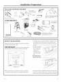
TOOLS AND MATERIALS REQUIRED
(NOT SUPPLIED} 7/16" Pivoting
hex socket with 4"
_sions
Wire cutter/ U
Duct tape
Pencil and tape measure
Spirit level
/
Step ladder
Carpenter's square
stripper
Safetg glasses
Sabersaw
or Sawsall
Pliers Metal Snips
Keg Hole Saw
Wire nuts
Flashlight
Electric or batterg operated drill
and 3/16", bits, Phillips and Flat
Blade Screwdriver bits.
10" round metal
duct, length to
suit installation.
Phillips and flat
screwdrivers
©
Strain relief for
junction cover.
120V 60Hz. 15 or 20 Amp,
2-wire with ground. Properlg
grounded branch circuit.
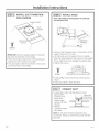
REMOVE THE PACKAGING
, Remove the parts packages and packing materials.
, Lift the hood out of the box.
IMPORTANT: Lift the hood bg grasping the
outside edges of the exhaust opening on the top.
" i Parts ,,
iParts/,
-,
i i
,,,,,/ Hood
Motor
7',' Mounted
' on Skid
J
ShippingCarton
J
Partsl
,i", _
J
, Place the hood on a protective surface to prevent
scratches and damage to the stainless steel finish.
Carefullg, lag the hood on its side. A support frame
is secured to the inside top of the hood. Remove
the attachment screws at the outside top. Discard
screws.
,Grasp the support
frame inside the
hood with both \
\
hands and
carefullg rotate
out of the open-
ing.
Be careful not to
scratch the hood,
,The hood motor is shipped secured to the skid with
a screws. Locate and remove 2 screws on each side
of the motor. Discard the shipping skid and screws.
Z_9 80209 5 9

Installation Preparation
PARTS PROVIDED
Locate the parts packed with the hood.
Allen Wrench
Implement rods with standoffs
0000
Duct collar
2Grease trags (3with 54" hood)
Transition with Damper
2-piece decorative duct cover
2 Filters (3 with 54" hood)
Support frame for 8 ft. ceiling
with 4 large pan head screws
installed on the bottom corners.
Decorative top cover
HAR DWAR E PACKAG E
Locate and check
contents. Screws
shown actual size.
i_s "",
2Templates
if
Screws C:
8 blunt point
Phillips
screws
Screws A
4 (7/16")
hex head
wood
screws
Screws B
2 (!/8" x !-!/2")
Phillips
pan head
screws.
Screw F
Blower safetg screw and lock washer,
Phillips head Ivl6 x 16.
Note: Hardware appearance mag varg slightlg.
EZ]3
T
Screws D
2 small
Phillips
head
screws
?
Screws E
2 Phillips
head wood
screws
ACCESSO RY PACKAG E
Check accessorg package.
Select the taller set for 9'6" to 10'8" ceilings.
Select the shorter set for 8'6" to 9'6" ceilings.
Discard unused set.
I
i
"_- L_ J
2 Support Frames
with 8 height
adjustment
screws
2 Sets of Duct Covers
S
i
4 Attachment Screws
0 49 80209 5

Installation instructions
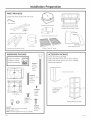
ISTEP 11 CONSTRUCT CEILING SUPPORT
Plan the Location of the Hood and Ductwork
, Use a plumb bob to check the location. The
countertop/cooktop below the hood must be centered
with the hood.
Ceiling
Hood
.......Ducting
Centerline
Front
i
31-3/4" ,:
Align With
Center of ................... i
Cooktop
_ Cooktop
i /j
_____________ Countertop
42" HoodSide View
, The hood should extend beyond the front and rear
edge of the cooking appliance.
, The duct in the ceiling must be centered over the
cooktop.
Ceil.ing
i Hood
i J.........Ducting
i'-l Centerline
Mp i , ,
1
Align With _36-1/4'i _"
I
Center of ................. i CooktoF
Cooktop _
........ Counter
54" Hood Side View
Ceiling Support Structure
, At the hood location, install 2 x 4 cross framing
between ceiling joists as shown. (2x4's are required to
support the weight of the hood.)
EXAMPLE A
12-3/4" (42" Hood)
17" (54" Hood)Install
Cross-Framing
Sgmmetricallg About -_
Duct/Cooktop Centerline
, Arrange cross framing in the ceiling to suit the exist-
ing structure.
, Your ceiling joists will be like one of the following
examples.
I
i
_'Cooktop
Outline
Top View - Ceiling Joists Parallel to Front of Hood

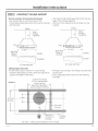
Installation instructions
ISTEP iI CONSTRUCT CEILING SUPPORT
CONTINUED
EXAMPLE B
16" Jois
Spacing
12-3/4" (42"
Hood) 17" (54"
Hoodt Install
Cross-Framing
Sgmmetricallg
About Duct/ -_
Cooktop Centerline
2x4 Cross
g
Align duct
to center
of Cooktop
\
Cooktop
Outline
Top View - Ceiling Joists Run Perpendicular to Front of Hood
EXAMPLE C
Z2-3/z_" (42" Hood)
17" (54" Hood)Install Cross-Framin(
Sgmmetricallg About Duct/Cooktop
Centerline
2x4 Cross
Framing
16" Joist
Spacing
_'_ Align duct \
to center Cooktop
of Cooktop Outline
Top View - Ceiling Joists at Angle with Front of Hood
12 49 80209 5

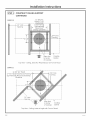
Installation instructions
ISTEP 11 CONSTRUCT CEILING SUPPORT
CONTINUED
, Secure each 2 x 4 block with at least four (4),#10
wood screws, 3" long (not supplied). Use 8 wood
screws total for the two supports.
, The cross framing must be accurately aligned to
assure correct positioning of the hood.
, The cross framing must be level in all directions.
Check with a spirit level and adjust if necessarg.
IMPORTANT: The ceiling structure must be capable
of supporting the weight of the hood (approximatelg
300 pounds) and ang inadvertent user contact loads.
The hood support frame will be supported bg the 2 x
4 cross framing.
Ductwork
, Use the shortest and straightest duct route possible.
For satisfactorg performance, duct run should not
exceed 150 feet equivalent length for ang duct
configuration.
, Refer to "Duct Fittings" chart to compute the
maximum permissible length for duct runs to the
outdoors.
, This vent hood must use 10" round rigid duct.
, Install the house ductwork to run horizontallg
between ceiling joists or straight up through the
roof.
2x 4 Min.
Cross Framing
Ceiling .,7 ':-
/8.......8-5
(54" Hoo(
12-3/4"
(42"Hoo(
Height
Adjustmen
Screw Hole
_zZZZZZ_
= i
= i
= =
i =
i
/
10"
Duct
VentStraight Up
ThroughThe Ceiling
Ceiling Joint
/
/
2x4
Finish the Ceiling
, Finish the ceiling surface. Be sure to mark location
of the ceiling joists and cross framing. Check to be
sure the ceiling is level, use shims if necessary.

Installation instructions
ISTEP2J MOUNT TEMPLATE
. Select the template for gour hood size. _;_ !ff-_"_ F"
"andAligntapetheintemplateplace,with the marks on the ceiling _ UI_
l
- Be sure the template is oriented correctlg, [][][]
with the front of the hood.
. Use a plumb to check to be sure the mount- ".
ing holes will provide parallel alignment with
the countertop below, cr ....
. Center punch all hole locations.
. Drill pilot holes in the 4 screw locations. Use a
3/16" bit and drill approximatelg 1-1/2" deep.
. Drive 4 Hex head wood screws (Screws A)into
the center of the ceiling joists and cross fram-
ing. Leave a 1/4" gap to allow the screw head
to engage the keghole slots on the support
frames.
, Cut the 10-1/2" duct opening through the
sheet rock.
STEP 31 SIZE AND INSTALL DUCTWORK
. Measure from house duct flange to bottom of
support frame. Subtract 4-3/8" for clearance to the
bottom of the support frame.
. Cut the 10" duct length to size.
. Secure duct to house ducting with sheet metal
screws.
. Seal all connections with duct tape.
. Attach the duct collar Iooselg, about 1" from the
bottom of the duct using Screws B.
.....................i...........
i_-!l I" Duct
Duct::):1 14
c°llar"i"-i-._:!::_'
•-;.......... : 4-3/8" Clearance
II/'
_o___ o, to Bottom of Fran
_4 49 80209 5

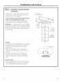
Installation Instructions
STEP 4] INSTALL ACCESSORY (OR SUPPLIED) SUPPORT AND DUCT COVERS
i'
/
/
Install
Safetg Screw
on Each Side
?
Screws E
Adjust
Frame to
nstallation
Height
Install Small Pan Hea
Screws on Each Side
/
iF
Screws D
Install Stop
Screw \
Stop Screw
Storage Location
Install supplied support frame OR telescoping accessorg
frame
, Hang the supplied support frame or telescoping
accessory frame to the ceiling joists and cross
framing on the 4 hex head screws by engaging the
keyhole slots on the frame.
, Check to be sure the support frame is level, vertically
and horizontally.
, Tighten the hex head screws securely.
, Install safety screws, (Screws E)on each side of the
frame.
Adjust telescoping accessorg frame to length
, Remove the 8 frame adjustment screws. Adjust the
lower support up or down to the pre-determined
length. Reinstall and securelg tighten the 8
adjustment screws.
, Slide the top (inner) accessorg duct cover up and
over the frame. Secure the duct cover to the frame as
shown using Screws D.
, Locate and remove the safetg stop screw. Slide
bottom duct cover up and over the top duct cover.
Align bottom duct screw hole to the hole in the
frame. Hold the duct cover in place while installing
screw.
_L,/_V|lVl_: The stop screw
must be installed. Failure to do so could result in
personal injurg or damage to the duct cover. The stop
screw will prevent the lower duct from sliding down
while completing the installation.
APRUDENCE
II faut mettre en place la vis de but6e afin d'6viter des
blessures ou d'endommager I'enceinte du conduit. La
vis de but6e emp_che I'enceinte inf@ieure du conduit
de descendre pendant I'installation.
Secure house wiring
, Route house wiring through the ceiling and pull a
length to reach the hood junction box, approximatelg
6" below the support. Tape to the right side of the
support frame.
IMPORTANT: Again, check to be sure the support is
level in both directions. There is no wag to level the
hood after the hood is secured to the frame.

Installation instructions
ISTEP5J
INSTALL DUCT TRANSITION
WITH DAMPER
Pads
i
/
Duct
Transition
Screws C
Attachmen
Screws
INPORTANT: Remove shipping tape from damper
and check that damper moves freelg.
, Place the transition piece over the hood exhaust
and secure with 4 Screws C provided.
, Use duct tape to seal the connection. Check to be
sure the damper moves freelg.
ISTEP6J INSTALL HOOD
Note: THREE PEOPLE ARE REQUIRED TO COMPLETE
THIS INSTALLATION!
/
Attachment /
Keyholes_
, Back out the hanging screws on the bottom of the
support frame to a 1/4" gap.
, Lift the hood up to the support frame. Carefullg
align the hood keghole to the screws on the support
frame. Slide the hood to engage the keghole slots.
, Tighten the screws.
Screws C
Install
I-2Safetg I
I Screws
, Install safetg screws into the top of the hood as
shown.
, Check hood level in both directions.
[STEP7J CONNECT DUCT
, Loosen duct collar and slide down to cover
gap between
transition and
house duct.
Tighten collar
screws and tape _. _...o:
alljoints.
, Seal all k
connections with
duct tape.
Slide Duct
Collar Down
to Cover Gap
Note: Do not drive screws through this duct
connection. Doing so will prevent proper damper
operation.
16 49 80209 5

Installation Instructions
STEP 8 ! CONNECT ELECTRICAL
Verifg thot power is turned off ot the source.
WARNING: housewiringisnot2-wire
with o ground wire, o ground must be provided bg
the installer. When house wiring is aluminum, be
sure to use UL approved anti-oxidant compound
and aluminum-to-copper connectors.
ATTENTION - silec_blagede la
maison n'estpas du tgpe (_deu× filsavec un filde
terre, I'installateur dolt fournir un circuit de terre.
Quond les ills de Io moison sont en oluminium,
il prendre soin d'utiliser de Io p_te ontioxido-
tion opprouv6e par UL et des connecteurs pour
I'oluminium-cuivre.
, Install strain relief onto the knockout of the
junction box.
, Insert house wiring through strain relief and tighten.
, Use wire nuts to connect incoming ground to green,
white to white and block to block.
, Push wires into junction box and replace cover. Be
sure wires ore not pinched.
STEP 91 INSTALL THE MOTOR
Screw F
Outlet
\
Attachment
Slot
;I
/
€--
Spring
Clip
©
Attochment Screw
ond Wosher
/_,
f--
Attachment Spring
Slot Clip
, From the inside of the hood, slip motor into the
attachment slot on the left.
, Rotate motor upwards until it snaps into the spring
clip on the right.
, Secure the motor to the hood with the machine
screw and lock washer (Screw is marked with red
point.)
, Plug blower cable into the connector on the blower.
IMPORTANT: Connector
ends ore designed to
mote onlg one wag.
Hatch flat and round
connectors us shown.
¢ ....", ¢
, Plug cable at the top of the hood into the junction
box connector. Route cable so it won't be pinched
or damaged when the duct cover is lowered.

installation instructions
ISTEP i0] SLIDE DUCT COVER DOWN
SKIP THIS STEP IF USING THE SUPPLIED DUCT
COVER
, Hold the duct cover in place and remove the
temporGrg stop screw. Return the screw to the
storage location for future use.
, Slide the lower duct cover down onto the hood.
t Remove \
Ductt _ _ \
Storage Location
STEP 11 INSTALL FILTERS
, Place filter drip trags into the rear of the hood.
, Insert the filter into the upper opening and drop
into the trags.
, To remove the filters, grasp the knobs and push
the filter up and lift out.
ISTEP 12] INSTALL RODS
, Use a flat blade screwdriver to install stand-offs
into the bottom of the hood.
, Align implement rod to stand-offs with the screw
hole towards the inside of the hood. Secure the rod
to the stand-offs with the supplied Allen wrench.
, Follow the same procedure on the opposite side.
.\
Screw
Stand-offs
Into Hood
J
/
Allen ....
Wrench to /'
",,, Secure Rod /
\
\_to Stand-offsf
18 49 80209 5

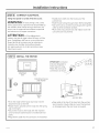
Installation Instructions
STEP 13 INSTALL SUPPLIED DUCT
COVER AND TOP COVER
iF
Screws O
lnstall Duct
CoverScrew
n EachSide
, Install the supplied 2-piece duct cover over the
support frame (if using supplied frame). Snap ends
together.
, Secure duct covers to support frame with 2
Screws D.
, For o more finished appearance, a top cover is
supplied and should be installed whenever the top
of the hood is visible.
TIP:Place pieces
of tape over ends
of the cover to
prevent scratch-
ing the duct
cover. Remove
tape before
installing screws.
,,Tab.<
, Engage tabs into slots on each side at the top of
the hood. The covers should lag flat in the impres-
sion on top of the hood.
Screws C
ove
/
Install Screws t\
Front and Back
, Install 2 Screws C to secure the cover to the hood
at the front and back.
[STEP 14] FINALIZE INSTALLATION
, Check all lamps to assure tightness in sockets.
, Turn power on at the circuit breaker.
, Refer to the Owner's Hanual for operating and
cleaning instructions.
STEP 151 INSTALLATION CHECKLIST
Check Blower Safetg Screw
[] Ensure that blower safetg screw is securelg tight-
ened. See page 16, Step 9. If screw is missing, order
replacement ports bag.
Check Operating Sound and Proper Air-Flow
[] Turn blower to each speed setting and listen for
rattles and vibration. You should notice an audible
difference at each speed setting.
[] Check for foreign material in transition.
[] Check that blower screen is not damaged or pushed
into the blower impeller.
[] The damper should move freely. Listen for opening
and closing while turning the unit on and off.
[] Check that the damper is not damaged, does not
vibrate and that damper bumper pads are in place.
Order a damper replacement assembly if needed.
[] Check that ductwork is 10" round. If duct type is not
rigid and less than 10" round, inform the consumer
that performance will be reduced.
Check Lighting Function
[] Check that power cable is plugged into the junction
box on top of the hood.
[] Turn halogen lamps to each setting. Note change in
brightness at different settings.
[] Check that each lamp bezel is secure. Turn to the
right to tighten. Order replacement lamp bezel and
socket assemblies if needed.
Check appearance and installation
[] Use a spirit level to check that the hood is level.
Review installation instructions to determine source
of problem.
[] Top covers (if used) should lay flat in the recess on
top of the hood. Hake sure side tabs are engaged in
slots and the cover is secured with two screws.
[]
Clean the hood surfaces and all filters. See the
Owner's Hanual for cleaning instructions. They
should be free of construction debris such as
sawdust.

Note: While performing instollotions described in this book,
sofetg glosses or goggles should beworn.
For Monogrom ®/oco/service in your oreo, co//
1.800.¢¢¢.18¢5.
Note: Product improvement is mcontinuing endemvor mt
Generol Electric. Therefore, moteriols, oppeoronce ond sped-
ficotions ore subject to chonge without notice.
149-80209-5 1
02-13 GE
Printed in Mexico
GE Appliances & Lighting
Applionces
Gener(]l Electric Comp(]ny
Louisville, KY/40225
GEApplionces.com
-
 1
1
-
 2
2
-
 3
3
-
 4
4
-
 5
5
-
 6
6
-
 7
7
-
 8
8
-
 9
9
-
 10
10
-
 11
11
-
 12
12
-
 13
13
-
 14
14
-
 15
15
-
 16
16
-
 17
17
-
 18
18
-
 19
19
-
 20
20


GE ZV42ISH1SS Guide d'installation
- Catégorie
- Hottes
- Taper
- Guide d'installation
- Ce manuel convient également à
dans d''autres langues
- English: GE ZV42ISH1SS Installation guide
Documents connexes
-
GE ZV850SP1SS Guide d'installation
-
-
-
-
-
GE Monogram ZV855SPSS Guide d'installation
-
 GE Monogram ZV755SPSS Guide d'installation
-

Autres documents
-
Monogram GEZV925SLSS Guide d'installation
-
-
-
-
 GE Monogram ZV855SPSS Installation Instructions Manual
-
 GE Monogram GEZV925SLSS Guide d'installation
-
Monogram ZV900SLSS Guide d'installation
-
Fakro 869719 Guide d'installation
-
Ryobi P2760-SS Manuel utilisateur

