Hobart HL600, HL662, HL800, HL1400 Legacy+ Mixers Manuel utilisateur
- Catégorie
- Mélangeurs
- Taper
- Manuel utilisateur

701 S. RIDGE AVENUE
TROY, OHIO 45374-0001
937 332-3000
www.hobartcorp.com
INSTRUCTIONS
MANUAL
MODELS
HL600
HL600C
HL662
HL800
HL800C
HL1400
HL1400C
Page 1 - English
Page 25 - Spanish
Page 49 - French F48154 (May 2021)

– 2 –
ITW Food Equipment Group © HOBART 2021
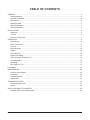
TABLE OF CONTENTS
GENERAL .................................................................................................................................................................3
Safety Guidelines ................................................................................................................................................4
Operation Guidelines ..........................................................................................................................................4
Dust Hazard ........................................................................................................................................................5
Warning Symbol ..................................................................................................................................................5
Warranty Disclaimer ............................................................................................................................................5
General Information ............................................................................................................................................5
INSTALLATION ........................................................................................................................................................6
Unpacking ...........................................................................................................................................................6
Location ..............................................................................................................................................................6
Electrical Connections ........................................................................................................................................7
OPERATION ............................................................................................................................................................8
Initial Checks .......................................................................................................................................................8
Mixer Components ..............................................................................................................................................9
Controls .............................................................................................................................................................12
Bowl Placement ................................................................................................................................................13
Agitator ..............................................................................................................................................................14
Power Bowl Lift .................................................................................................................................................14
Prepare For Mixing ...........................................................................................................................................15
Timer Operation (SmartTimer™).......................................................................................................................15
Operating Notes ................................................................................................................................................16
Unloading ..........................................................................................................................................................17
Wire Cage (Fig. 13) ...........................................................................................................................................17
CLEANING .............................................................................................................................................................19
MAINTENANCE .....................................................................................................................................................20
Interlock Safety System ...................................................................................................................................20
Lubrication ........................................................................................................................................................20
Transmission Belt ..............................................................................................................................................21
Adjustments ......................................................................................................................................................21
TROUBLESHOOTING ..........................................................................................................................................23
Troubleshooting Guide ......................................................................................................................................23
Service ..............................................................................................................................................................23
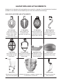
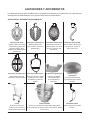
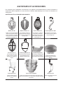
AGITATORS AND ATTACHMENTS ......................................................................................................................24
Available Agitators and Attachments .................................................................................................................24

– 3 –
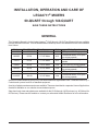
INSTALLATION, OPERATION AND CARE OF
LEGACY+® MIXERS
60-QUART through 140-QUART
SAVE THESE INSTRUCTIONS
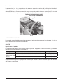
GENERAL
This Operation Manual is for the Hobart Legacy+® 60-Qt through 140-Qt Floor Mixers which are available
LQWKUHHGLႇHUHQWERZOVL]HV9LVLWWKHZHEVLWHZZZKREDUWFRUSFRPWRVHHDGGLWLRQDOPL[HUVL]HVDYDLODEOH
from Hobart.
Device Bowl Size (Qt) Motor Horsepower Hub Mixing Speeds
HL600 60-Qt 2.7 HP Motor #12 STIR, plus four mixing speeds
HL600C 60-Qt 2.7 HP Motor #12 Correctional Mixer, STIR, plus
four mixing speeds
HL662 60-Qt 2.7 HP Motor #12 Pizza Mixer, two mixing
speeds
HL800 80-Qt 3.0 HP Motor N/A STIR, plus four mixing speeds
HL800C 80-Qt 3.0 HP Motor N/A Correctional Mixer, STIR, plus
four mixing speeds
HL1400 140-Qt 5.0 HP Motor N/A STIR, plus four mixing speeds
HL1400C 140-Qt 5.0 HP Motor N/A Correctional Mixer, STIR, plus
four mixing speeds
All sizes of Hobart Maximum Heavy Duty Floor Mixers feature a digital SmartTimer™ with Shift-on-the-Fly™
Controls and a power bowl lift as standard equipment.
A variety of agitators and accessories are available. These are described in a separate Use and Applications
Handbook available on our website at www.hobartcorp.com.
Step down bowl sizes and agitators are available for the 60-Qt through 140-Qt mixers (e.g. 40-Qt bowl for
60-Qt mixer). Please see the website or contact you authorized Hobart Distributor for more information.

– 4 –
SAFETY GUIDELINES
• All operators must be properly trained in the safe operation of the mixer and attachments.
• To avoid risk of serious injury follow all precautions and instructions in this manual when installing,
operating, and servicing the mixer.
• To avoid risk of serious injury, keep hands, feet, clothing, and utensils away from the bowl, bowl
support, slideways, and agitator when the mixer is in operation or any of the components are
moving.
• Do not operate the mixer if it is not in proper operating condition.
• Disconnect power to the mixer and follow lockout-tagout procedures before moving or servicing
the mixer.
• Do not operate the mixer if parts are disassembled.
• Do not override safety switches on the mixer.
• When moving the mixer make sure it is stable to avoid tipping and keep hands and feet clear of
the bottom of the mixer to avoid pinching.
• Use the STOP button to stop the mixer. Never open the wire cage or use the power bowl lift to
stop the mixer.
• Do not wear loose clothing around the mixer.
'RQRWLQKDOHGXVWSDUWLFOHVIURPPL[LQJLQJUHGLHQWV([SRVXUHWRGXVWLQFOXGLQJÀRXUPD\EH
harmful to health. When mixing ingredients that develop dust use the STIR speed until the dust is
eliminated and follow the instructions in the DUST HAZARD section below.
• Do not install or leave an agitator on the mixer without a bowl in place.
'RQRWXVHH[FHVVLYHIRUFHZKHQRSHUDWLQJZKLFKFRXOGDႇHFWWKHVWDELOLW\RIWKHPL[HU
OPERATION GUIDELINES
• Use the correct sized bowl only with agitators for that sized bowl. Double check the sizes
when using a reduced sized bowl, by consulting the mixer accessories chart available
at www.hobartcorp.com.
(QVXUHWKHERZODJLWDWRUDQGZLUHFDJHDUHFRUUHFWO\¿WWHGWRWKHPL[HU
• Stop the mixer before adding more ingredients unless using a food chute.
• Have your mixer regularly serviced; at least twice a year for typical usage. Mixers may require
more or less service depending on frequency of use.
• Use the mixer in a well-lit area.
• Ensure this manual is kept in an easily accessible place near the mixer for future reference.
• Do not clean the mixer with scouring powder or a scouring pad.
• Do not clean aluminum agitators in dishwashers.
• Do not hose or pressure clean the mixer. It is important to adhere to the cleaning instructions
detailed in the CLEANING section of the manual.

– 5 –
DUST HAZARD
In order to minimize any dust hazard, follow the instructions detailed below.
:KHQPL[LQJLQJUHGLHQWVFDUHPXVWEHWDNHQWRDYRLGWKHLQKDODWLRQRIGXVWSDUWLFOHVHJÀRXU5HIHUHQFH
should be made to the product supplier’s data sheets to ensure adequate precautions and protections
are taken.
,QJUHGLHQWVVXFKDVÀRXUPXVWEHDGGHGFDUHIXOO\WRPLQLPL]HDLUERUQHGXVWSDUWLFOHV
Carefully slit the bag while holding it in the lower part of the bowl. When mixing dry ingredients use the
lowest speed and a splash cover to minimize dust emission. Mix the ingredients in the bowl using the
lowest speed until the risk of producing any dust is eliminated. Fit suitable dust extraction equipment.
WARNING SYMBOL
To identify the safety messages in this manual, the following symbol has been used.
The WARNING symbol is located in the manual before information corresponding
to the safe use of the mixer.
WARRANTY DISCLAIMER
,QVWDOODWLRQVDQGUHSDLUVFDUULHGRXWE\QRQDXWKRUL]HGVHUYLFHWHFKQLFLDQVPD\DႇHFWWKHPL[HUZDUUDQW\
8VLQJRWKHUWKDQRULJLQDOUHSODFHPHQWSDUWVPD\DႇHFWWKHPL[HUZDUUDQW\7HFKQLFDODOWHUDWLRQVWRWKH
PL[HUPD\DႇHFWWKHPL[HUZDUUDQW\
For warranty information, please contact Hobart Customer Care.
GENERAL INFORMATION
Hobart reserves the right to alter the design of its products without prior notice. If you have questions
UHJDUGLQJPL[HUGHWDLOVQRWLQFOXGHGLQWKLVPDQXDOFRQWDFW\RXUORFDO+REDUW6HUYLFH2ႈFH

– 6 –
INSTALLATION
UNPACKING
The mixer was inspected before leaving the factory. The carrier assumes full responsibility for the safe
delivery of the mixer upon acceptance of the mixer for shipping. The customer must check for possible
shipping damage immediately upon receipt before moving, installing, or modifying the mixer.
If damage is found, keep all original packaging materials for inspection purposes. The customer must
complete the following steps to report the damage.
&DUULHU¶VORFDOWHUPLQDOPXVWEHQRWL¿HGZLWKLQEXVLQHVVGD\VRIVKLSPHQWUHFHLSWQRWHWLPH
GDWHDQGZKRZDVVSRNHQWRDQGIROORZXSDQGFRQ¿UPZLWKZULWWHQRUHOHFWURQLFFRPPXQLFD-
tion.
2. Notify Hobart customer care at (800) 333-7447 within 5 business days of shipment receipt.
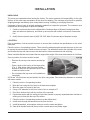
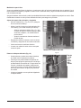
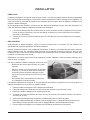
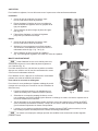
LOCATION
3ULRUWRLQVWDOODWLRQWHVWWKHHOHFWULFDOVHUYLFHWRHQVXUHWKDWLWPDWFKHVWKHVSHFL¿FDWLRQVRQWKHPL[HU
data plate.
Place the mixer in its operating location. There should be adequate space around the mixer for the user
to operate the controls and to install and remove bowls. The area above and to the right side of the mixer
should allow the top and side covers to be removed for routine maintenance and servicing.
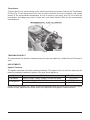
6HOHFWDVXLWDEOHÀDWDQGOHYHOVXUIDFHWKDWFDQVXSSRUWWKHZHLJKWRIWKHPL[HUDQGFRQWHQWVRIDIXOOERZO
Once in position, the mixer must be leveled:
• Remove the two top cover screws and the top
cover.
• Place a level on the top rim of the large pulley
(Fig. 1). Slide shims under the base contact
surface of the mixer as required to level it front-
to-back and side-to-side.
• Do not replace the top cover until installation is
completed.
4WDQG4WPL[HUVPD\EHEROWHGWRWKHÀRRUXVLQJVWXGV)ORRUDQFKRULQJKDUGZDUHLVLQFOXGHG
with some models.
1. Place the mixer in its operating location.
0DUNWKHÀRRUXVLQJWKHIRXUKROHVLQWKHEDVHDVDWHPSODWH
0RYHWKHPL[HUIRUDFFHVVWRWKHÀRRU
8VLQJDGLDPHWHUELWGULOOIRXUKROHVLQÀRRUWRDGHSWKRI
'ULYHÀRRUDQFKRUVÀXVKZLWKWKHVXUIDFHRIWKHFRQFUHWH
6. Expand the anchor with the setting tool provided. Anchor is properly expanded when shoulder of
VHWWLQJWRROLVÀXVKZLWKWKHWRSRIWKHDQFKRU
7. Place the mixer in its operating location over the drilled holes.
,QVWDOOVWXGVWKURXJKWKHEDVHDQGLQWRWKHÀRRUDQFKRUV
,QVWDOOÀDWZDVKHUVORFNZDVKHUVDQGQXWVRQWRWKHVWXGVDQGWLJKWHQ
6DZRႇDOOWKUHDGVÀXVKZLWKWKHWRSRIWKHQXWDQGUHPRYHDQ\VKDUSHGJHV
Fig. 1

– 7 –
ELECTRICAL CONNECTIONS
Electrical and grounding connections must comply with the applicable portion
of the National Electrical Code and/or other local electrical codes.
Disconnect the electrical power to the mixer and follow lockout / tagout
procedures.
A hole for 3/4"-trade-size conduit is located at the top of the pedestal. Make electrical connections per the
wiring diagram located on the inside of the top cover.
Single-Phase Mixer:
&RQQHFW¿HOGVXSSO\OHDGZLUHVWR/DQG/
• Connect ground wire to ground lug on the mixer.
&XWRႇVWULSSHGSRUWLRQRI/RQ/HJDF\® Mixer and wrap securely with electrical tape to insulate
the exposed conductor.
Three-Phase Mixer:
&RQQHFW¿HOGVXSSO\OHDGZLUHVWR//DQG/
• Connect ground wire to ground lug on the mixer.

– 8 –
OPERATION
INITIAL CHECKS
To avoid risk of serious injury, keep hands, feet, clothing, and utensils away from
the bowl, bowl support, slideways, and agitator when the mixer is in operation or when any of
the components are moving.
This food mixer is only for professional use by properly trained persons.
Ensure operators have read and understood this manual and have received
proper training.
Do not use the mixer without the interlocked wire cage in place.
The Legacy+® mixer is equipped with SmartTimer™ controls and a power bowl lift. Other operating parts
(Fig. 3, Fig. 4, and Fig. 5) and their functions are described throughout the Operation section.
The wire cage must be in position or the mixer will not operate.
The bowl must stay in the locked position on the bowl support or the mixer will not operate.
If the bowl support is not all the way up (mix position), the mixer will not operate unless the START button
is pressed and held.
If the bowl support is not in the mix position and the START button is pressed and held, the mixer will
operate only in STIR speed.
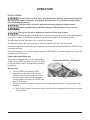
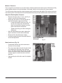
Check Lubrication Before Use
This mixer is shipped with oil in the transmission.
Check oil level before starting mixer (Fig. 2). Refer
to the Lubrication section for applicable lubrication
procedures.
Wiring Check
1. Turn the SPEED dial pointer to STIR.
2. Apply power to the mixer. With the bowl
locked into place, the bowl support all the
way up and wire cage closed, momentarily
run the machine by pushing the START and
then STOP buttons.
9HULI\WKDWWKHERZOOLIWUDLVHVDQGORZHUVSHUWKHVZLWFKGLUHFWLRQDUURZV,IQRWSURFHHGWRVWHS
3a below.
a. Refer to the Electrical Connections section and follow all warnings and instructions to correct
the lead wires.
Fig. 2
Transmission Fill Plug / Oil Dipstick

– 9 –
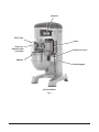
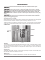
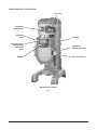
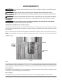
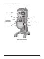
MIXER COMPONENTS
60-Quart Mixer
Fig. 3
Controls
Apron
Bowl Support
Bowl Lock Lever
Attachment Hub
Wire Cage
Agitator
Drip Cup-
Splash Guard
Assembly

– 10 –
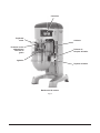
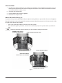
80-Quart Mixer
Fig. 4
Controls
Wire Cage
Agitator
Drip Cup-
Splash Guard
Assembly
Apron
Bowl Support
Bowl Lock Lever

– 11 –
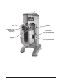
140-Quart Mixer
Fig. 5
Controls
Wire Cage
Agitator
Drip Cup-
Splash Guard
Assembly
Apron
Bowl Support
Bowl Lock Lever

– 12 –
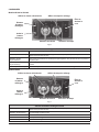
CONTROLS
Models HL600 and HL600C
HL600 and HL600C Mixer Speeds
STIR (Slow) For incorporating ingredients
SPEED 1 (Low) For heavy mixtures such as pizza dough, heavy batters, and potatoes
SPEED 2 (Medium-Low) For mixing cake batters, mashing potatoes, and developing bread dough
SPEED 3 (Medium-High) )RULQFRUSRUDWLQJDLULQWREDWFKHVDVZHOODV¿QLVKLQJZKLSSHGLWHPV
SPEED 4 (High) For maximum, accelerated air incorporation into light batches
Model HL662
HL662 Mixer Speeds
SPEED 1 (Slow) For heavy mixtures such as pizza dough, heavy batters, and potatoes
SPEED 2 (Low) For developing pizza dough
MEAT GRIND For grinding meat
CHEESE SHRED For shredding cheese
9(*(7$%/(6/,&( For slicing vegetables
Time Selector
Starts
Mixer
Stops
Mixer
Raises
and Lowers
Mixing Bowl
Speed Selector
Displays Selected Mix Speed Displays Mixing Time
Fig. 6
Time Selector
Starts
Mixer
Stops
Mixer
Raises
and Lowers
Mixing Bowl
Speed Selector
Displays Selected Mix Speed Displays Mixing Time
Fig. 7

– 13 –
Models HL800, HL800C, HL1400, and HL1400C
HL800, HL800C, HL1400, and HL1400C Mixer Speeds
STIR (Slow) For incorporating ingredients
SPEED 1 (Low) For heavy mixtures such as pizza dough, heavy batters, and potatoes
SPEED 2 (Medium-Low) For mixing cake batters, mashing potatoes, and developing bread dough
SPEED 3 (Medium-High) )RULQFRUSRUDWLQJDLULQWREDWFKHVDVZHOODV¿QLVKLQJZKLSSHGLWHPV
SPEED 4 (High) For maximum, accelerated air incorporation into light batches
BOWL PLACEMENT
The bowl must be installed onto the bowl support before the agitator is installed. The bowl is
heavy and must be correctly handled and lifted to avoid personal injury.
To Install
1. Fully lower the bowl support by pressing
and holding the down arrow on the bowl
switch (Fig. 6, Fig. 7, and Fig. 8).
2. Position the bowl so the alignment pins
on the left side of the bowl support
)LJ¿WLQWKHKROHVLQWKHERZO
3. Swing the bowl into the locked position on
bowl support (Fig. 9).
To Remove
Before lowering the bowl onto a bowl
truck, always unlock the bowl and swing the bowl
out slightly.
1. Lower the bowl by pressing and holding the down arrow on the bowl switch (Fig. 6, Fig. 7, and
Fig. 8).
2. Unlock bowl and swing out slightly from the locked position.
3. Open the wire cage and remove the agitator.
Time Selector
Starts
Mixer
Stops
Mixer
Raises
and Lowers
Mixing Bowl
Speed Selector
Displays Selected Mix Speed Displays Mixing Time
Fig. 8
Fig. 9

– 14 –
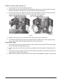
AGITATOR
To install an agitator, the bowl must be on the bowl support and fully lowered.
To Install
1. Open the wire cage. Refer to the Wire Cage sec-
tion as needed.
2. Place the agitator inside the bowl and align the
horizontal slot on the agitator with the agitator
shaft pins.
3. Hold the agitator and pull the plunger pin of the
agitator out (Fig. 10).
4. Slide the agitator up the agitator shaft until it
stops and latches.
To Remove
1. Open the wire cage. Refer to the Wire Cage sec-
tion as needed.
2. Lower the bowl by pressing and holding the down
arrow on the bowl switch (Fig. 6, Fig. 7, and Fig. 8)
+ROGWKHDJLWDWRUDQGSXOOWKHSOXQJHURIWKHDJLWDWRURXW)LJ6OLGHWKHDJLWDWRUGRZQRႇWKH
agitator shaft.
POWER BOWL LIFT
Before lowering the bowl onto a bowl truck,
always unlock bowl and swing bowl out slightly (Fig. 11).
To raise the bowl, the bowl must be in the locked position.
Push and hold the up arrow on the bowl switch.
To lower the bowl, push and hold the down arrow on the
bowl switch.
To Raise the Bowl While Mixing
To raise the bowl while the agitator is mixing the product
(when required by recipe or when using the bowl scraper
attachment):
1. Close the wire cage, then select a mixing speed
on the SPEED dial.
2. Select a count-down time or HOLD for continu-
ous count-up mixing. Refer to the Timer Operation
section as needed.
3. While pressing and holding the up arrow on the bowl switch, press and hold the START button.
The mixer runs only in stir speed while the bowl is rising.
4. When the bowl reaches the mix position, release the START button. The mixer automatically
changes to the selected mixing speed.
Mixing speed and time can be adjusted any time during the mixing operation without
stopping the mixer.
Fig. 10
Fig. 11

– 15 –
PREPARE FOR MIXING
1. Open the wire cage. Refer to the Wire Cage section as
needed.
2. Place the mixing bowl on the bowl support.
3. Pour ingredients into the bowl.
4. Swing the bowl to the locked position.
5. Place the agitator inside the bowl, then attach it to the
agitator shaft (Fig. 12).
6. Return the wire cage to the front-center position
(Fig. 13).
7. Push and hold the up arrow on the bowl switch until the
bowl reaches the mix position and stops.
8. The mixer is now ready for mixing. Refer to the Timer
Operation section.
TIMER OPERATION (SmartTimer™)
Using the Count-Up Mode (Continuous Mixing)
1. Turn the SPEED dial to select a mix speed (the SPEED setting can be changed at any time dur-
ing mixing).
Only use STIR for incorporating ingredients. Do not use to develop dough products.
2. Set the timer on hold by turning the TIME selector counterclockwise until "Hold" appears in the
TIME window.
3. Press the START button to begin mixing. The timer starts to count up from 00:00.
If the wire cage is opened at any time, mixing stops. To resume mixing, close the wire cage
and press the START button.
4. Press the STOP button to stop the mixer; the mixing time is displayed in the TIME window.
5. Press the START button to resume mixing if needed.
When the timer reaches 20:00 minutes, it rolls over to 00:01 and continues counting until the
STOP button is pressed.
Fig. 12

– 16 –
Using the Count-Down Mode (Timed Mixing)
1. Turn the SPEED dial to select a mix speed.
a. If the count-up mode was used for the previous batch, the desired time needs to be entered.
b. If the count-down mode was used for the previous batch, the previous time is displayed. If a
GLႇHUHQWWLPHLVQHHGHGWXUQWKH7,0(VHOHFWRUWRWKHGHVLUHGWLPH
2. Press the START button to begin mixing; the timer starts counting down from the set time.
a. To stop the mixer at any time, press the STOP button. To resume mixing, press the START
button. For example: The mixer is started at SPEED 1 for 30 seconds and is stopped after
10 seconds. Pressing the START button will resume mixing.
b. If the mixer is stopped and a new time setting is entered, pressing the START button saves
the new time setting on the current speed selection. For example: The mixer is started at
SPEED 1 for 30 seconds and is stopped after 10 seconds. A new time is entered by turn-
ing the TIME selector. The new time replaces the initial 30 seconds for SPEED 1 after the
START button is pressed.
c. If the time is changed while mixing, the mixer operates until the new time expires. The ad-
justment to the time is not stored.
d. If the speed is changed while mixing, the time reverts to the previously set time for the se-
lected speed and counts down.
The agitator does not stop immediately. To avoid risk of serious injury, keep
hands, clothing, and utensils out of the mixing bowl and away from the agitator as the agitator
winds down.
If the wire cage is opened at any time, the mixing stops. To resume the mixing, close the wire
cage and press the START button.
3. When the timer reaches 00:00, the mixer stops; a beeper sounds for 3 seconds. The count-down
timer displays the last-entered time.
OPERATING NOTES
• Only use STIR for incorporating ingredients. Do not use it to develop dough products.
• If the mixer is stopped during mixing, the timer also stops. The timer starts again (with the time
remaining) when the START button is pressed.
• The SPEED window displays the current SPEED selection.
• Turn the TIME selector clockwise to take the mixer out of the hold mode.

– 17 –
UNLOADING
1. After the mixer has stopped, and the agitator comes to rest, unlock the bowl and swing-out
slightly. Press and hold the down arrow on the bowl switch to lower the bowl.
2. Open the wire cage assembly.
3. Remove the agitator from the agitator shaft.
4. Remove the bowl from the bowl support.
WIRE CAGE (Fig. 13)
The wire cage can be rotated out of the way to add ingredients or to access the bowl and agitator.
Note how the grooves on the retainer shoes allow the wire cage to ride around the circular ridge of the
planetary drip cup.
• To open the wire cage: rotate it to your left.
• To close the wire cage: rotate it to your right until it stops in the front-center, closed position.
The wire cage must be returned to the closed position for the mixer to operate.
Fig. 13

– 18 –
Remove and Clean Wire Cage (Fig. 14)
1. Lower the bowl. Remove the agitator and bowl.
2. While holding the wire cage securely with both hands, rotate it to your left until the front-center
retainer shoe reaches the gap in the circular ridge of the planetary drip cup.
3. Lower the front of the wire cage and move the wire cage slightly to the rear so the rear retainer
shoes clear the ridge of the drip cup. The wire cage can now be removed.
Fig. 14
4. Wash the wire cage in a sink, rinse with clear water, and dry with a clean cloth.
7KHVWDLQOHVVVWHHOVSODVKJXDUGFDQEHZLSHGRႇDQGRUZDVKHGZLWKDFORWKRUVSRQJHXVLQJ
warm, soapy water. Rinse with clear water and dry with a clean cloth.
Reinstall Wire Cage
1. Position the ring of the wire cage so the front-center retainer shoe is positioned below the gap in
the circular ridge of the planetary drip cup.
2. Position the grooves so the rear retainer shoes straddle the circular ridge on the planetary drip
cup.
3. Lift the front of the wire cage so the front-center retainer shoe passes up through the gap in the
circular ridge on the planetary drip cup.
4. Rotate the wire cage to your right until all three retainer shoes straddle the ridge on the drip cup.

– 19 –
CLEANING
Disconnect the electrical power to the mixer and follow lockout / tagout
procedures.
New mixer bowls and accessories (beaters, whips, and dough arms) should be thoroughly washed with
hot water and a mild soap solution, rinsed with either a mild soda or vinegar solution and thoroughly
rinsed with clear water before being used. This cleaning procedure should also be followed for bowls and
agitators before whipping egg whites or whole eggs.
The mixer should be thoroughly cleaned daily. DO NOT use a hose to clean the mixer; it should be washed
with a clean, damp cloth. The base allows ample room for cleaning under the mixer. The apron (Fig. 3,
Fig. 4, and Fig. 5) may be removed for cleaning by loosening the thumb screws. DO NOT wipe down
slideways (Fig. 15) when cleaning.
The drip cup-splash guard assembly (Fig. 3, Fig. 4, and Fig. 5) should be removed periodically and wiped
clean.
For cleaning the wire cage refer to the Wire Cage section.

– 20 –
MAINTENANCE
Disconnect the electrical power to the mixer and follow lockout / tagout
procedures.
'RQRWUHPRYHDQ\FRYHUVRUORRVHQDQ\¿WWLQJVZKLOHWKHPL[HULVRSHUDWLQJ
Ensure the electrical supply has been isolated before attempting to service or move the mixer.
7KHHOHFWURQLFGULYHFRQWUROLV¿WWHGZLWKKLJKYROWDJHFDSDFLWRUV,VRODWHWKH
mixer from the mains and allow the capacitors to discharge for 5 minutes before removing any
covers.
2QO\+REDUWWUDLQHGVHUYLFHSHUVRQQHORURWKHUSURSHUO\WUDLQHGDQGTXDOL¿HG
personnel should carry out service.
INTERLOCK SAFETY SYSTEM
Regular inspection of the mixer's safety system is necessary to check the operation of the wire cage and
bowl support interlock switches. Inspections must be performed no less than once a year.
A spare parts manual is available from Hobart Resource Center. For continued safe and reliable operation
of this mixer, it is recommended that servicing is only carried out by Hobart trained service personnel.
LUBRICATION
Fig. 15
Slideways
The slideways (Fig. 15) should be lubricated approximately twice a year. To reach these areas, fully lower
the bowl support and remove the apron (Fig. 3, Fig. 4, and Fig. 5), which is secured by thumb screws.
Wipe a thin coat of Lubriplate 630AA on the bowl pad area of the bowl supports and on each slideway.
Install the apron.
Planetary Seal
Occasionally, the planetary seal (Fig. 15) may become dry and begin to squeak. To correct this, work a
little lubrication (mineral oil) under the lip of the seal.
Agitator Shaft
The agitator shaft (Fig. 15) should be lubricated twice a year with a thin coat of mineral oil.
AGITATOR
SHAFT
La page est en cours de chargement...
La page est en cours de chargement...
La page est en cours de chargement...
La page est en cours de chargement...
La page est en cours de chargement...
La page est en cours de chargement...
La page est en cours de chargement...
La page est en cours de chargement...
La page est en cours de chargement...
La page est en cours de chargement...
La page est en cours de chargement...
La page est en cours de chargement...
La page est en cours de chargement...
La page est en cours de chargement...
La page est en cours de chargement...
La page est en cours de chargement...
La page est en cours de chargement...
La page est en cours de chargement...
La page est en cours de chargement...
La page est en cours de chargement...
La page est en cours de chargement...
La page est en cours de chargement...
La page est en cours de chargement...
La page est en cours de chargement...
La page est en cours de chargement...
La page est en cours de chargement...
La page est en cours de chargement...
La page est en cours de chargement...
La page est en cours de chargement...
La page est en cours de chargement...
La page est en cours de chargement...
La page est en cours de chargement...
La page est en cours de chargement...
La page est en cours de chargement...
La page est en cours de chargement...
La page est en cours de chargement...
La page est en cours de chargement...
La page est en cours de chargement...
La page est en cours de chargement...
La page est en cours de chargement...
La page est en cours de chargement...
La page est en cours de chargement...
La page est en cours de chargement...
La page est en cours de chargement...
La page est en cours de chargement...
La page est en cours de chargement...
La page est en cours de chargement...
La page est en cours de chargement...
La page est en cours de chargement...
La page est en cours de chargement...
La page est en cours de chargement...
La page est en cours de chargement...
-
 1
1
-
 2
2
-
 3
3
-
 4
4
-
 5
5
-
 6
6
-
 7
7
-
 8
8
-
 9
9
-
 10
10
-
 11
11
-
 12
12
-
 13
13
-
 14
14
-
 15
15
-
 16
16
-
 17
17
-
 18
18
-
 19
19
-
 20
20
-
 21
21
-
 22
22
-
 23
23
-
 24
24
-
 25
25
-
 26
26
-
 27
27
-
 28
28
-
 29
29
-
 30
30
-
 31
31
-
 32
32
-
 33
33
-
 34
34
-
 35
35
-
 36
36
-
 37
37
-
 38
38
-
 39
39
-
 40
40
-
 41
41
-
 42
42
-
 43
43
-
 44
44
-
 45
45
-
 46
46
-
 47
47
-
 48
48
-
 49
49
-
 50
50
-
 51
51
-
 52
52
-
 53
53
-
 54
54
-
 55
55
-
 56
56
-
 57
57
-
 58
58
-
 59
59
-
 60
60
-
 61
61
-
 62
62
-
 63
63
-
 64
64
-
 65
65
-
 66
66
-
 67
67
-
 68
68
-
 69
69
-
 70
70
-
 71
71
-
 72
72


Hobart HL600, HL662, HL800, HL1400 Legacy+ Mixers Manuel utilisateur
- Catégorie
- Mélangeurs
- Taper
- Manuel utilisateur
dans d''autres langues
Documents connexes
-
Hobart LEGACYHL200 Manuel utilisateur
-
Hobart HL1400N Mode d'emploi
-
-
-
Hobart ML-141105 Manuel utilisateur
-
-
-
-