Bosch 9173790 Le manuel du propriétaire
- Catégorie
- Outils électroportatifs
- Taper
- Le manuel du propriétaire

For English Version
See page 2
Version française
Voir page 23
Versión en español
Ver la página 44
IMPORTANT
Read Before Using
IMPORTANT
Lire avant usage
IMPORTANTE
Leer antes de usar
Operating / Safety Instructions
Consignes d’utilisation / de sécurité
Instrucciones de funcionamiento y seguridad
Call Toll Free for Consumer Information & Service Locations
Pour obtenir des informations et les adresses de nos centres de service après-vente, appelez ce numéro gratuit
Llame gratis para obtener información para el consumidor y ubicaciones de servicio
1-877-BOSCH99 (1-877-267-2499) www.boschtools.com
GKM18V-20

-2-
General Power Tool Safety Warnings
Read all safety warnings, instructions, illustrations and specifications provid-
ed with this power tool. Failure to follow all instructions listed below may result
in electric shock, fire and/or serious injury.
SAVE ALL WARNINGS AND INSTRUCTIONS FOR FUTURE REFERENCE
The term “power tool” in the warnings refers to your mains-operated (corded) power tool or
battery-operated (cordless) power tool.
1. Work area safety
a. Keep work area clean and well lit. Cluttered
or dark areas invite accidents.
b. Do not operate power tools in explosive
atmospheres, such as in the presence of
ammable liquids, gases or dust. Power
tools create sparks which may ignite the dust
or fumes.
c. Keep children and bystanders away while
operating a power tool. Distractions can
cause you to lose control.
2. Electrical safety
a. Power tool plugs must match the outlet.
Never modify the plug in any way. Do not use
any adapter plugs with earthed (grounded)
power tools. Unmodified plugs and matching
outlets will reduce risk of electric shock.
b. Avoid body contact with earthed or ground-
ed surfaces, such as pipes, radiators, rang-
es and refrigerators. There is an increased
risk of electric shock if your body is earthed
or grounded.
c. Do not expose power tools to rain or wet
conditions. Water entering a power tool will
increase the risk of electric shock.
d. Do not abuse the cord. Never use the cord
for carrying, pulling or unplugging the power
tool. Keep cord away from heat, oil, sharp
edges or moving parts. Damaged or entan-
gled cords increase the risk of electric shock.
e. When operating a power tool outdoors, use
an extension cord suitable for outdoor use.
Use of a cord suitable for outdoor use reduc-
es the risk of electric shock.
f. If operating a power tool in a damp location
is unavoidable, use a Ground Fault Circuit
Interrupter (GFCI) protected supply. Use of
an GFCI reduces the risk of electric shock.
3. Personal safety
a. Stay alert, watch what you are doing and
use common sense when operating a power
tool. Do not use a power tool while you are
tired or under the inuence of drugs, alco-
hol or medication. A moment of inattention
while operating power tools may result in se-
rious personal injury.
Safety Symbols
The definitions below describe the level of severity for each signal word.
Please read the manual and pay attention to these symbols.
!
This is the safety alert symbol. It is used to alert you to potential
personal injury hazards. Obey all safety messages that follow this
symbol to avoid possible injury or death.
DANGER indicates a hazardous situation which, if not avoided, will
result in death or serious injury.
WARNING indicates a hazardous situation which, if not avoided,
could result in death or serious injury.
CAUTION indicates a hazardous situation which, if not avoided, could
result in minor or moderate injury.

-3-
page headingGeneral Power Tool Safety Warnings
b. Use personal protective equipment. Always
wear eye protection. Protective equipment
such as a dust mask, non-skid safety shoes,
hard hat, or hearing protection used for ap-
propriate conditions will reduce personal
injuries.
c. Prevent unintentional starting. Ensure the
switch is in the off-position before connect-
ing to power source and / or battery pack,
picking up or carrying the tool. Carrying
power tools with your finger on the switch or
energizing power tools that have the switch
on invites accidents.
d. Remove any adjusting key or wrench before
turning the power tool on. A wrench or a key
left attached to a rotating part of the power
tool may result in personal injury.
e. Do not overreach. Keep proper footing and
balance at all times. This enables better con-
trol of the power tool in unexpected situa-
tions.
f. Dress properly. Do not wear loose clothing
or jewelry. Keep your hair and clothing away
from moving parts. Loose clothes, jewelry or
long hair can be caught in moving parts.
g. If devices are provided for the connection
of dust extraction and collection facilities,
ensure these are connected and properly
used. Use of dust collection can reduce
dust-related hazards.
h. Do not let familiarity gained from frequent
use of tools allow you to become compla-
cent and ignore tool safety principles. A
careless action can cause severe injury with-
in a fraction of a second.
4. Power tool use and care
a. Do not force the power tool. Use the correct
power tool for your application. The correct
power tool will do the job better and safer at
the rate for which it was designed.
b. Do not use the power tool if the switch
does not turn it on and off. Any power tool
that cannot be controlled with the switch is
dangerous and must be repaired.
c. Disconnect the plug from the power source
and/or remove the battery pack, if detach-
able, from the power tool before making
any adjustments, changing accessories, or
storing power tools. Such preventive safe-
ty measures reduce the risk of starting the
power tool accidentally.
d. Store idle power tools out of the reach of
children and do not allow persons unfamil-
iar with the power tool or these instructions
to operate the power tool. Power tools are
dangerous in the hands of untrained users.
e. Maintain power tools and accessories.
Check for misalignment or binding of mov-
ing parts, breakage of parts and any other
condition that may affect the power tool’s
operation. If damaged, have the power tool
repaired before use. Many accidents are
caused by poorly maintained power tools.
f. Keep cutting tools sharp and clean. Prop-
erly maintained cutting tools with sharp
cutting edges are less likely to bind and are
easier to control.
g. Use the power tool, accessories and tool
bits etc. in accordance with these instruc-
tions, taking into account the working condi-
tions and the work to be performed. Use of
the power tool for operations different from
those intended could result in a hazardous
situation.
h. Keep handles and grasping surfaces dry,
clean and free from oil and grease. Slippery
handles and grasping surfaces do not allow
for safe handling and control of the tool in
unexpected situations.
5. Battery tool use and care
a. Recharge only with the charger specified
by the manufacturer. A charger that is suit-
able for one type of battery pack may create
a risk of fire when used with another battery
pack.
b. Use power tools only with specifically des-
ignated battery packs. Use of any other bat-
tery packs may create a risk of injury and fire.
c. When battery pack is not in use, keep it
away from other metal objects like paper
clips, coins, keys, nails, screws, or other
small metal objects that can make a con-
nection from one terminal to another.
Shorting the battery terminals together may
cause burns or a fire.
d. Under abusive conditions, liquid may be
ejected from the battery; avoid contact. If
contact accidentally occurs, ush with wa-
ter. If liquid contacts eyes, additionally seek

-4-
General Power Tool Safety Warnings
medical help. Liquid ejected from the bat-
tery may cause irritation or burns.
e. Do not use a battery pack or tool that is
damaged or modified. Damaged or modified
batteries may exhibit unpredictable behavior
resulting in fire, explosion or risk of injury.
f. Do not expose a battery pack or tool to fire
or excessive temperature. Exposure to fire
or temperature above 265 °F may cause ex-
plosion.
g. Follow all charging instructions and do not
charge the battery pack or tool outside the
temperature range specified in the instruc-
tions. Charging improperly or at tempera-
tures outside the specified range may dam-
age the battery and increase the risk of fire.
6. Service
a. Have your power tool serviced by a quali-
fied repair person using only identical re-
placement parts. This will ensure that the
safety of the power tool is maintained.
b. Never service damaged battery packs. Ser-
vice of battery packs should only be per-
formed by the manufacturer or authorized
service providers.
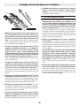
1. Cutting Procedures
a. Keep hands away from
cutting area and the
blade. Keep your second hand on auxiliary
handle, or motor housing. If both hands are
holding the saw, they cannot be cut by the
blade.
b. Do not reach underneath the workpiece.
The guard cannot protect you from the blade
below the workpiece.
c. Adjust the cutting depth to the thickness
of the workpiece. Less than a full tooth of
the blade teeth should be visible below the
workpiece.
d. Never hold the workpiece in your hands
or across your leg while cutting. Secure
the workpiece to a stable platform. It is
important to support the work properly to
minimize body exposure, blade binding, or
loss of control.
e. Hold the power tool by insulated gripping
surfaces, when performing an operation
where the cutting tool may contact hidden
wiring. Contact with a “live” wire will also
make exposed metal parts of the power tool
“live” and could give the operator an elec-
tric shock.
f. When ripping, always use a rip fence or
straight edge guide. This improves the ac-
curacy of cut and reduces the chance of
blade binding.
g. Always use blades with correct size and
shape (diamond versus round) of arbor
holes. Blades that do not match the mount-
ing hardware of the saw will run off-center,
causing loss of control.
h. Never use damaged or incorrect blade
washers or bolt. The blade washers and
bolt were specially designed for your saw,
for optimum performance and safety of op-
eration.
2. Kickback Causes and Related
Warnings
Kickback is a sudden reaction to a pinched,
jammed or misaligned saw blade, causing an
uncontrolled saw to lift up and out of the work-
piece toward the operator.
When the blade is pinched or jammed tightly
by the kerf closing down, the blade stalls and
the motor reaction drives the unit rapidly back
toward the operator.
If the blade becomes twisted or misaligned in
the cut, the teeth at the back edge of the blade
can dig into the top surface of the wood caus-
ing the blade to climb out of the kerf and jump
back toward the operator.
Kickback is the result of saw misuse and/or in-
correct operating procedures or conditions and
can be avoided by taking proper precautions as
given below:
Safety Instructions for Circular Saws

-5-
Safety Instructions for Circular Saws
Kickback
a. Maintain a firm grip with both hands on the
saw and position your arms to resist kick-
back forces. Position your body to either
side of the blade, but not in line with the
blade. Kickback could cause the saw to jump
backwards, but kickback forces can be con-
trolled by the operator, if proper precautions
are taken.
b. When blade is binding, or when interrupt-
ing a cut for any reason, release the trigger
and hold the saw motionless in the mate-
rial until the blade comes to a complete
stop. Never attempt to remove the saw
from the work or pull the saw backward
while the blade is in motion or kickback
may occur. Investigate and take corrective
actions to eliminate the cause of blade
binding.
c. When restarting a saw in the workpiece,
center the saw blade in the kerf so that the
saw teeth are not engaged into the mate-
rial. If a saw blade binds, it may walk up or
kickback from the workpiece as the saw is
restarted.
d. Support large panels to minimize the risk
of blade pinching and kickback. Large pan-
els tend to sag under their own weight. Sup-
ports must be placed under the panel on
both sides, near the line of cut and near the
edge of the panel.
e. Do not use dull or damaged blades. Un-
sharpened or improperly set blades pro-
duce narrow kerf causing excessive friction,
blade binding and kickback.
f. Blade depth and bevel adjusting locking le-
vers must be tight and secure before mak-
ing cut. If blade adjustment shifts while cut-
ting, it may cause binding and kickback.
g. Use extra caution when sawing into exist-
ing walls or other blind areas. The protrud-
ing blade may cut objects that can cause
kickback.
3. Lower Guard Function
a. Check the lower guard for proper closing
before each use. Do not operate the saw if
the lower guard does not move freely and
close instantly. Never clamp or tie the low-
er guard into the open position. If the saw
is accidentally dropped, the lower guard
may be bent. Raise the lower guard with the
retracting handle and make sure it moves
freely and does not touch the blade or any
other part, in all angles and depths of cut.
b. Check the operation of the lower guard
spring. If the guard and the spring are not
operating properly, they must be serviced
before use. Lower guard may operate slug-
gishly due to damaged parts, gummy depos-
its, or a buildup of debris.
c. The lower guard may be retracted manu-
ally only for special cuts such as “plunge
cuts” and “compound cuts”. Raise the
lower guard by the retracting handle and
as soon as the blade enters the material,
the lower guard must be released. For all
other sawing, the lower guard should oper-
ate automatically.
d. Always observe that the lower guard is
covering the blade before placing saw
down on bench or oor. An unprotected,
coasting blade will cause the saw to walk
backwards, cutting whatever is in its path.
Be aware of the time it takes for the blade
to stop after switch is released.

-6-
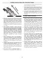
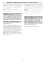
Additional Safety Instructions for Circular Saws
a. This product is intended to cut metal prod-
ucts only. Dust build up around the lower
guard and hub from other materials (plastic,
masonry or wood) may disable the lower
guard operation.
b. Hold the saw firmly to prevent loss of con-
trol. Figures in this manual illustrate typical
hand support of the saw.
c. Depending upon use, the switch may not
last the life of the saw. If the switch should
fail in the “OFF” position, the saw may not
start. If it should fail while the saw is run-
ning, the saw may not shut off. If either oc-
curs, remove the battery pack from the saw
immediately and do not use until repaired.
d. This circular saw should not be mounted to
a table and converted to a table saw. Circu-
lar saws are not designed or intended to be
used as table saws.
e. The blade washers and the bolt on your saw
have been designed to work as a clutch to
reduce the intensity of a kickback. Under-
stand the operation and settings of the VARI-
TORQUE CLUTCH. The proper setting of the
clutch, combined with firm handling of the
saw will allow you to control kickback.
f. Never place your hand behind the saw
blade. Kickback could cause the saw to jump
backwards over your hand.
g. Do not use the saw with an excessive depth
of cut setting. Too much blade exposure in-
creases the likelihood of the blade twisting
in the kerf and increases the surface area of
the blade available for pinching that leads to
kickback.
h. Do not run the tool while carrying it at your
side. Lower guard may be opened by a con-
tact with your clothing. Accidental contact
with the spinning saw blade could result in
serious personal injury.
i. Periodically remove the blade, clean the
upper, lower guards and the hub area with
kerosene and wipe it dry. Preventive main-
tenance and properly operating guard will
reduce the probability of an accident.
j. Ensure the switch is in the off position be-
fore inserting battery pack. Inserting the
battery pack into power tools that have the
switch on invites accidents.
k. Avoid overheating saw blade tips.

-7-
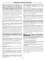
Additional Safety Warnings
Wear personal protective equipments. De-
pending on application, use face shield, safety
goggles or safety glasses for eye protection.
Wear hearing protectors, gloves and workshop
apron capable of stopping small metal chips
or workpiece fragments. The eye protection
must be capable of stopping ying debris gen-
erated by various operations. The gloves, work-
shop apron and clothing must be fire resistant.
Prolonged exposure to high intensity noise may
cause hearing loss. Using protective equipments
will reduce the risk of personal injuries.
GFCI and personal protection devices like elec-
trician’s rubber gloves and footwear will further
enhance your personal safety.
Do not touch workpiece after it has just been
cut. Workpiece may be hot and lead to burn haz-
ard.
Do not handle workpiece without wearing
gloves. The sharp edge of workpiece may cause
a laceration hazard.
Keep bystanders a safe distance away from
work area. Anyone entering the work area must
wear personal protective equipments (eye and
ear protection, etc). Fragments of workpiece or
of a broken accessory may y away and cause
injury beyond immediate area of operation.
After finishing the cut, release the switch, hold
the saw steady and wait for blade to stop be-
fore removing work or cutoff piece. REACHING
WITH YOUR HAND UNDER A COASTING BLADE
IS DANGEROUS!
Only use 5-3/8” metal cutting blades recom-
mended in this manual. Do not use abrasive
wheels. Using blades not recommended in this
manual can result in a hazardous situation.
Do not use dull blade. Additional sparks gener-
ated by using dull blade increase the risk of a
fire hazard.
Do not use cutting oil. The use of cutting oil may
cause a fire.
Do not use tool near ammable material.
Sparks may cause fire.
Do not cut workpieces covered or stained with
gas, oil, solvents, thinners, etc. Exposure to
these materials may damage the transparent
guard.
Let the blade reach full speed before contact-
ing the workpiece. This will help avoid thrown
workpieces.
When cleaning do not combine hot metal chips
with combustible materials. The hot metal
chips may ignite combustible materials and
cause a fire hazard.
Do not use dust extraction for operations
where dust may include burning, smoking
or smoldering items like hot metal chips or
sparks. Fire inside the vacuum tank or bag may
occur. Dust may smolder and set vacuum on fire
long after work is completed.
Do not use dust extraction when working on
metal. Chips from cutting metal may be hot and
may spark which may melt plastic adaptors,
vacuum hoses and may cause a fire inside the
vacuum tank or bag.
If the transparent guard is missing or damaged
do not operate tool and return it to authorized
Bosch service center for repair. Using tool with
damaged or missing transparent guard can lead
to serious personal injury.
Develop a periodic maintenance schedule for
your tool. When cleaning a tool be careful not
to disassemble any portion of the tool since
internal wires may be misplaced or pinched or
safety guard return springs may be improperly
mounted. Certain cleaning agents such as gaso-
line, carbon tetrachloride, ammonia, etc. may
damage plastic parts.
Some dust created by power
sanding, sawing, grinding,
drilling, and other construction activities con-
tains chemicals known to cause cancer, birth
defects or other reproductive harm. Some ex-
amples of these chemicals are:
• Lead from lead-based paints,
• Crystalline silica from bricks and cement and
other masonry products, and
• Arsenic and chromium from chemically-treat-
ed lumber.
Your risk from these exposures varies, depend-
ing on how often you do this type of work. To re-
duce your exposure to these chemicals: work in
a well ventilated area, and work with approved
safety equipment, such as those dust masks
that are specially designed to filter out micro-
scopic particles.

-8-
page heading
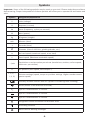
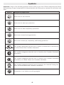
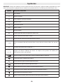
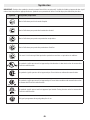
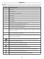
Symbols
Important: Some of the following symbols may be used on your tool. Please study them and learn
their meaning. Proper interpretation of these symbols will allow you to operate the tool better and
safer.
Symbol Designation/Explanation
V Volts (voltage)
A Amperes (current)
Hz Hertz (frequency, cycles per second)
W Watt (power)
kg Kilograms (weight)
min Minutes (time)
s Seconds (time)
⌀Diameter (size of drill bits, grinding wheels, etc.)
n0No load speed (rotational speed, at no load)
nRated speed (Maximum attainable speed)
.../min Revolutions or reciprocation per minute (revolutions, strokes, surface speed,
orbits etc. per minute)
0Off position (zero speed, zero torque...)
1, 2, 3, ...
I, II, III,
Selector settings (speed, torque or position settings. Higher number means
greater speed)
Infinitely variable selector with off (speed is increasing from 0 setting)
Arrow (action in the direction of arrow)
Type or a characteristic of current
Type or a characteristic of current
Type or a characteristic of current
Designates Double Insulated Construction tools
Grounding terminal
Alerts user to warning messages

-9-
page heading
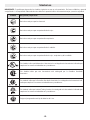
Symbols
Important: Some of the following symbols may be used on your tool. Please study them and learn
their meaning. Proper interpretation of these symbols will allow you to operate the tool better and
safer.
Symbol Designation/Explanation
Alerts user to read manual.
Alerts user to wear eye protection.
Alerts user to wear respiratory protection.
Alerts user to wear hearing protection.
Alerts user to wear eye, respiratory, and hearing protection.
This symbol designates that this tool is listed by Underwriters Laboratories,
to United States and Canadian Standards.
This symbol designates that this tool is listed by the Canadian Standards
Association.
This symbol designates that this tool is listed by the Canadian Standards
Association, to United States and Canadian Standards.
This symbol designates that this tool is listed by the Intertek Testing Ser-
vices, to United States and Canadian Standards.
Designates Li-ion battery recycling program.

-10-
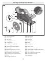
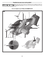
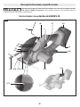
Getting to Know Your Product
(1)
(2)
(3)
(4)
(5)
(6) (7)(8)
(9)
(10)
(11)
(13)(14)(15)
(16)
(17)
(12)
Disconnect battery pack from tool before making any assembly, adjustments
or changing accessories. Such preventive safety measures reduce the risk of
starting the tool accidentally.
Bosch GKM18V-20 Cordless Circular Saw
Fig. 1

-11-
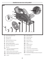
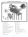
Getting to Know Your Product
(1)
(5)
(22)
(18) (19) (20) (21) (23) (24) (12) (13) (25)
(26)
(28)
(27)
Fig. 2
(1) Shaft Lock Button
(2) Upper Guard
(3) Saw Hook
(4) Cutting Depth Scale
(5) Blade Wrench
(6) Lock-Off Release Button
(7) On/Off Trigger Switch
(8) Battery Pack Release Button*
(9) Battery Pack*
(10) Depth Adjustment Lock Lever
(11) Auxiliary Handle/Motor Housing
(12) Transparent Guard Window
(13) Cut Alignment Arrow and Notch
(14) Foot
(15) Straight Edge Guide*
(16) Main Handle
(17) LED Light
(18) Blade Stud
(19) Outer Washer
(20) Blade
(21) Inner Washer
(22) Blade Shaft
(23) Lower Guard
(24) Lower Guard Lift Lever
(25) Straight Edge Guide Mounting Screw*
(26) Chip Container
(27) Chip Container Locking Slider
(28) Blade Wrench Storage
* sold separately

-12-
page heading
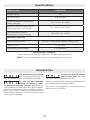
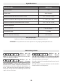
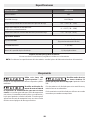
Battery Packs / Chargers:
Please refer to the battery/charger list, included with your tool.
NOTE: For tool specifications refer to the nameplate on your tool.
Model Number GKM18V-20
Voltage rating 18 V
No load speed 0—4,250 rpm
Permitted battery temperature
during charging +32…+113°F (0…+45C)
Permitted ambient temperature
during operation and storage -4…+122°F (-20…+50C)
Recommended ambient
temperature during charging +32…+95°F (0...+35°C)
Maximum Capacities
Recommended Blade Ø5-3/8” (20mm Arbor) Metal cutting blade
Depth of Cut 2” (51 mm)
Workpiece wall thickness 1/4” maximum
Specifications
Intended Use
Use this saw only as intend-
ed. Unintended use may re-
sult in personal injury and property damage.
Do not use Wet Diamond
cutting off wheel or water
feed devices with this circular saw. Masonry
cutting waste will enter the lower guard system,
harden and cause the guard to become inoper-
able. Use of water in masonry cutting applica-
tions with an electric circular saw will cause
electric shock hazards.
Do not use abrasive wheels
with circular saws. Abrasive
dust may cause lower guard to fail.
This tool is intended for cutting unhardened fer-
rous metal and non-ferrous metal.
This tool is not designed for use with wood or
masonry cut-off wheels.

-13-
page heading
Disconnect battery pack from tool before making any assembly, adjustments
or changing accessories. Such preventive safety measures reduce the risk of
starting the tool accidentally.
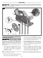
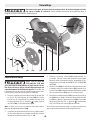
Assembly
Fig. 3
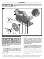
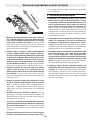
Attaching the Blade
Only use 5-3/8” (136mm)
metal cutting blades recom-
mended in this manual. Do not use abrasive
wheels. Only use a blade rated 4350 rpm or
greater. Using blade not designed for the saw
may result in serious personal injury and prop-
erty damage.
1. Press and hold the Shaft Lock Button (Fig. 3,
1). Turn Blade Stud (18) with the provided
wrench (5) counter-clockwise (Fig. 3, direc-
tion
1
) and remove Blade Stud (18) and
Outer Washer (19).
Note: The Blade Wrench is stored near the bat-
tery pack compartment (28).
2. Make sure the saw teeth and arrow on the
blade point in the same direction as the ar-
row on the Lower Guard (Fig 3, 23).
3. Retract the Lower Guard (23) all the way up
into the Upper Guard (2). While retracting
the lower guard, check operation and condi-
tion of the LOWER GUARD SPRING.
4. Slide Blade (20) through slot in the foot and
mount it against the Inner Washer (21) on
the Blade Shaft (22). Be sure the large di-
ameter of the Outer Washer (21) lays ush
against the blade.
5. Reinstall the Outer Washer (19) and tighten
Blade Stud (18) finger tight. Press Shaft
Lock Button (1) to tighten Blade Stud (18)
clockwise (Fig. 3, direction
2
) 1/8 turn (45°)
with the provided Blade Wrench (5).
Do not use wrenches with longer handles, since
it may lead to over tightening of the blade stud.
(1)
(5)
(22)
(18) (19) (20) (21) (23) (24)
(28)
(2)

-14-
page headingAssembly
(4) (10)
Fig. 4
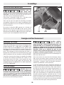
Inserting and Releasing Battery Pack
Use only Bosch batteries
recommended in the bat-
tery/charger list, included with your tool. Us-
ing other types of batteries may result in per-
sonal injury or property damage.
Slide charged Battery Pack (Fig. 1, 9) into the
housing until the Battery Pack locks into position.
Your tool is equipped with a secondary locking
latch to prevent the battery pack from complete-
ly falling out of the handle, should it become
loose due to vibration.
To remove the Battery Pack (9), press the Bat-
tery Pack Release Button (8) and slide the Bat-
tery Pack out. Press the Battery Pack Release
Button (8) again and slide the Battery Pack (9)
completely out of tool housing.
Vari-torque Clutch
This clutching action is provided by the friction
of the Outer Washer (Fig. 3, 19) against the
Blade (20) and permits the Blade Shaft (22) to
turn when the blade encounters excessive re-
sistance. when the Blade Stud (18) is properly
tightened (as described in no. 5 of Attaching
the Blade section), the blade will slip when it
encounters ex cessive resistance, thus reducing
saw’s tendency to KICKBACK.
One setting may not be sufficient for cutting all
materials. If ex cessive blade slippage occurs,
tighten the blade stud a fraction of a turn more
(less than 1/8 turn). OVERTIGHTENING THE
BLADE STUD NULLIFIES THE EFFECTIVENESS
OF THE CLUTCH.
Brake Action
Let the saw blade come to a
complete stop before set-
ting the tool down. The brake action of this cir-
cular saw is not intended as a safety feature.
Unintended contact with a rotating saw blade
can cause property damage and/or personal in-
jury.
Know the charge state of
your battery. The electric
braking action is initiated ONLY by the release
of the trigger switch and in a tool that has pow-
er available. When electrical power is lost due
to a discharged battery or other causes, the
electric brake will not operate and the motor
will gradually slow down. Unexpected run down
time may cause property damage and/or per-
sonal injury.
Your circular saw is equipped with an automatic
electric brake, which is designed to stop the
saw blade from spinning in approximately two
(2) seconds after you release the trigger switch.
This feature helps improve jobsite productivity.
Braking starts once the power is turned off. The
brake requires a charged battery to function.
Stopping time will vary depending on, among
other factors, saw blade used, and number of
actuations. The electric brake of your circular
saw has been designed for a high degree of reli-
ability, but unexpected circumstances such as
contamination or failure of the motor’s compo-
nents can cause the brake to not activate. If the
tool operates but the brake does not consistent-
ly stop the blade in about 2 seconds, DO NOT
use the circular saw and have it serviced by a
Bosch Factory Service Center or Bosch autho-
rized service facility.
Operation

-15-
Fig. 5
Operation
Protection Against Deep Discharging
The lithium ion battery is protected against deep
discharging by the “Electronic Cell Protection
(ECP)”. When the battery is empty, the tool is
switched off by means of a protective circuit.
Overload Protection
Your saw is equipped with Electronic Motor Pro-
tection (EMP), which shuts the tool off under
overload conditions that could damage the tool.
This feature can be reset by simply releasing the
trigger and re-engaging the trigger again to re-
start the tool.
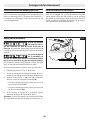
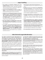
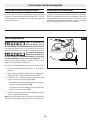
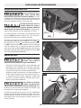
Depth Adjustment
Adjust the cutting depth so
that no more than one tooth
is visible below the work piece. Excessive blade
exposure below the workpiece could result in
personal injury and/or property damage.
The depth adjustment sys-
tem should not be used to
change the depth while the saw is in operation,
or for plunge cutting. If blade adjustment shifts
while cutting, it may cause binding and kick-
back.
To adjust the cutting depth follow these instruc-
tions:
A. Disconnect the Battery Pack (Fig. 1, 9) from
tool.
B. Loosen the Depth Adjustment Lock Lever
(Fig. 4, 21) located on the left side of the
tool.
C. Hold the Foot (Fig. 1, 14) down with one
hand and raise or lower saw by the Main
Handle (16).
– For a smaller cutting depth, pull the saw
away from the Foot (14);
– for a deeper cutting depth, push the saw
toward the Foot (14).
D. Tighten the depth adjustment lever at the
desired depth setting.
Note: Not more than one tooth length of the
blade should extend below the material to be
cut (Fig. 5).

-16-
page heading
Operation
Lock-Off Release Button and
On/Off Trigger Switch
When starting the tool, hold
it with both hands. The
torque from the motor can cause the tool to
twist.
The Lock-Off Release Button (Fig. 6, 6) is de-
signed to prevent accidental starts.
To turn tool “ON”, press the Lock-Off Release
Button (6) with your thumb on either side of the
handle to disengage the locking mechanism and
then pull the On/Off Trigger Switch (7). To turn
tool “OFF”, release the On/Off Trigger Switch
(7), which is spring loaded and will engage the
locking mechanism automatically.
Your saw should be running at full speed BE-
FORE starting the cut, and turned off only AF-
TER completing the cut. To increase switch life,
do not turn switch on and off while cutting.
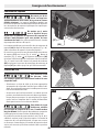
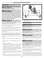
Line Guide
The Cut Alignment Arrow and Notch (Fig. 7, 13)
will give an approximate line of cut. Make sam-
ple cuts in scrap material to verify actual line of
cut. This will be helpful because of the number
of different blade types and thicknesses avail-
able.
LED Light
Your tool is equipped with a powerful LED light
(Fig. 1, 17) for better visibility when cutting. The
light has the ability to turn on when only partial-
ly depressing the On/Off Trigger Switch (Fig. 6,
7). The light will stay on for 5 seconds after the
switch has been released. This allows the cut
to be more visible before the saw blade begins
to spin. Once the blade is correctly situated for
the cut, depress the On/Off Trigger Switch (7)
completely and begin the cut. The light will stay
on during the duration of the cut and 5 seconds
after the switch has been released.
(13)
(7)
(6) Fig. 6
Fig. 7

-17-
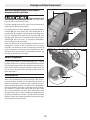
Operation
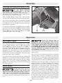
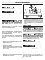
Chip Container
Do not cut material which
has had thinner, petrol,
grease or other chemicals applied to it. The
metal chips produced by such materials could
damage the protective guard with the Chip Con-
tainerand lead to a break that could cause per-
sonal injury.
Do not touch the protective
guard with Chip Contain-
erand the metal chips with bare hands imme-
diately after operation. These parts can be very
hot and cause skin burns.
The metal chips are collected in the Chip Con-
tainer (26) of the Upper Guard (Fig. 1, 2). Empty
the Chip Container at regular intervals.
To do this, push the Chip Container Locking
Slider(27) upwards (Fig. 8, action
1
). Open the
lid (Fig. 8, action
2
) of the Chip Container(26)
and tilt the power tool sideways to empty the
container (Fig. 9). After emptying, close the lid
of the container(26) by pushing the Chip Con-
tainer Locking Slider (27) downwards until it is
securely locked.
Saw Hook
To reduce the risk of injury,
use care in selecting the lo-
cation for hanging the tool.
• Select a suitably sized and shaped object that
will provide adequate hanging stability. An
unsuitable hanging surface could result in the
tool unexpectedly falling.
• Make sure that the tool is hung out of the way
of walkways and working areas with bystand-
ers. The tool could be bumped or a bystander
could become entangled, causing the tool to
unexpectedly fall.
To reduce the risk of injury,
do not use the saw hook if it
appears damaged or deformed. This could re-
sult in unstable hanging and the tool unexpect-
edly falling.
To use the saw hook (Fig. 10, 3), simply lift it
up to the required position. The saw hook can
be swiveled. When not in use, always close the
saw hook until it snaps into the closed position.
(26)
(27)
Fig. 8
Fig. 9
(3)
Fig. 10

-18-
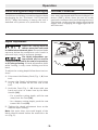
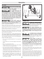
Plunge Cuts
Adjust the cutting depth to
the thickness of the work-
piece. Less than a full tooth of the blade teeth
should be visible below the workpiece.
The depth adjustment sys-
tem should not be used to
change the depth while the saw is in operation,
or for plunge cutting. If blade adjustment shifts
while cutting, it may cause binding and kick-
back.
As blade starts cutting the
material, release the lower
guard immediately. When the foot rests at on
the surface being cut, proceed cutting in for-
ward direction to end of cut.
Allow blade to come to a
complete stop before lifting
the saw from cut. Also, never pull the saw
backward since blade will climb out of the ma-
terial and KICKBACK will occur. Turn saw
around and finish the cut in the normal manner,
sawing forward. If corners of your plunge cut are
not completely cut through, use a jigsaw or hand
saw to finish the corners.
Disconnect battery pack from tool before mak-
ing ad justments. Set depth adjustment accord-
ing to material to be cut.
Hold the main handle of the saw with one hand,
tilt saw forward and rest front of the foot plate on
material to be cut. Line up the cutting guide notch
with the line you’ve drawn. Raise the lower guard
using lower guard lift lever and hold the front of
the foot plate with the other hand. (Fig. 11).
Operation
All Cuts
Always be sure either hand
does not interfere with the
free movement of the lower guard.
After completing a cut and
the trigger has been re-
leased, be aware of the necessary time it takes
for the blade to come to a complete stop dur-
ing coast down. Do not allow the saw to brush
against your leg or side, since the lower guard
is retractable, it could catch on your clothing
and expose the blade. Be aware of the neces-
sary blade exposures that exist in both the up-
per and lower guard areas.
Only use 5-3/8” metal cut-
ting blades recommended in
this manual. Do not use abrasive wheels. Using
blades not recommended in this manual can re-
sult in a hazardous situation.
Always hold the saw handle with one hand and
auxiliary handle/motor housing with the other.
Always make sure saw foot rests on portion of
work surface that does not drop off.
Maintain a firm grip and operate the switch with
a decisive action. Never force the saw. Use light
and continuous pressure.
This tool is intended for cutting unhardened fer-
rous metal. Refer to the accessories section for
a list of compatible blades based on application.
The following guidelines are to be followed to
reduce the risk of injury:
• Do not cut stacked materials. Cut one piece
at a time.
• Cut at least 1/2” from the edge of the work-
piece
• Do not cut hardened steel.
• Clamp material and cut with the wider edge
of the foot over the clamped side.
• Do not touch the saw blade, workpiece, or cut-
ting chips with bare hands, immediately after
cutting; they may be hot and could burn skin.
• Cut through the thinnest material section; ad-
justing the cutting angle of the blade to do so.
• When cutting is interrupted, to resume cut-
ting: squeeze the trigger and allow the blade
to reach full speed, re-enter the cut slowly
and resume cutting.
Fig. 11

-19-
Operation
Position the saw with the blade just clearing the
material to be cut. Start the motor and once ful-
ly up to speed, gradually lower the back end of
saw using the front end of the foot as the hinge
point.
Once the foot plate rests at on the surface be-
ing cut, release the lower guard and move the
hand holding the front of the foot plate to hold
the auxiliary handle. Proceed cutting in forward
direction to end of cut.
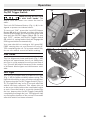
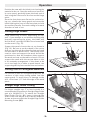
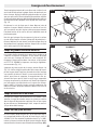
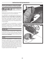
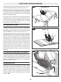
Cutting Large Sheets
Large sheets sag or bend, depending on sup-
port. If you attempt to cut without leveling and
properly supporting the piece, the blade will
tend to bind, causing KICK-BACK and extra load
on the motor (Fig. 12).
Support the panel close to the cut, as shown in
(Fig. 13). Be sure to set the depth of the cut so
that you cut through the sheet or plate only and
not the table or work bench. The two-by-fours
used to raise and support the work should be
positioned so that the broadest sides support
the work and rest on the table or bench. Do not
support the work with the narrow sides as this
is an unsteady arrangement. If the sheet to be
cut is too large for a table or work bench, use
supporting two-by-fours on the oor and secure.
Cutting Thin or Corrugated Materials
For cut-offs in thin or corrugated materials, be
cautious of thin strips being pulled into the
upper guard. To avoid injury or damage to the
tool, cut at least 1/2” from the edge of the work
piece.
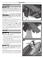
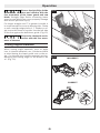
Straight Edge Guide Cutting
For longer straight cuts 5” or less in width, it is
recommended to use Bosch Straight Edge Guide
part p/n 2610347119. To attach the Straight
Edge Guide (Fig 14, 15), insert it through the
slots in the foot. Adjust to the desired width as
shown and secure with the Straight Edge Guide
Mounting Screw (25).
(15) (25)
Fig. 13
INCORRECT
CORRECT
Fig. 12
Fig. 14

-20-
page headingOperation
Ensure Straight Edge Guide
does not interfere with the
free movement of the lower guard and saw
blade. Straight Edge Guide contacting lower
guard or saw blade can cause property damage
and serious personal injury.
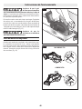
For longer straight cuts 5” or greater in width, it
is recommended to use a rip board guide. Clamp
or nail a straight edge piece of 1” lumber or an-
gle iron to the sheet as a guide. Use the left side
of the foot against the board as a guide. (Fig. 15)
Ensure the clamps do not in-
terfere with the free move-
ment of the saw.
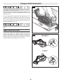
Cutting Angled Materials
When cutting angle materials, such as angle
iron, U-channel materials, etc., tilt the tool back
to avoid having the lower guard rest on the an-
gle. Cut through the thinnest material section;
adjusting the cutting angle of the blade to do
so. (Fig. 16)
Fig. 15
Fig. 16 INCORRECT
CORRECT
La page charge ...
La page charge ...
La page charge ...
La page charge ...
La page charge ...
La page charge ...
La page charge ...
La page charge ...
La page charge ...
La page charge ...
La page charge ...
La page charge ...
La page charge ...
La page charge ...
La page charge ...
La page charge ...
La page charge ...
La page charge ...
La page charge ...
La page charge ...
La page charge ...
La page charge ...
La page charge ...
La page charge ...
La page charge ...
La page charge ...
La page charge ...
La page charge ...
La page charge ...
La page charge ...
La page charge ...
La page charge ...
La page charge ...
La page charge ...
La page charge ...
La page charge ...
La page charge ...
La page charge ...
La page charge ...
La page charge ...
La page charge ...
La page charge ...
La page charge ...
La page charge ...
La page charge ...
La page charge ...
La page charge ...
La page charge ...
-
 1
1
-
 2
2
-
 3
3
-
 4
4
-
 5
5
-
 6
6
-
 7
7
-
 8
8
-
 9
9
-
 10
10
-
 11
11
-
 12
12
-
 13
13
-
 14
14
-
 15
15
-
 16
16
-
 17
17
-
 18
18
-
 19
19
-
 20
20
-
 21
21
-
 22
22
-
 23
23
-
 24
24
-
 25
25
-
 26
26
-
 27
27
-
 28
28
-
 29
29
-
 30
30
-
 31
31
-
 32
32
-
 33
33
-
 34
34
-
 35
35
-
 36
36
-
 37
37
-
 38
38
-
 39
39
-
 40
40
-
 41
41
-
 42
42
-
 43
43
-
 44
44
-
 45
45
-
 46
46
-
 47
47
-
 48
48
-
 49
49
-
 50
50
-
 51
51
-
 52
52
-
 53
53
-
 54
54
-
 55
55
-
 56
56
-
 57
57
-
 58
58
-
 59
59
-
 60
60
-
 61
61
-
 62
62
-
 63
63
-
 64
64
-
 65
65
-
 66
66
-
 67
67
-
 68
68


Bosch 9173790 Le manuel du propriétaire
- Catégorie
- Outils électroportatifs
- Taper
- Le manuel du propriétaire
dans d''autres langues
- English: Bosch 9173790 Owner's manual
- español: Bosch 9173790 El manual del propietario