Raychem NGC-20-C(L)-E Guide d'installation
- Taper
- Guide d'installation

11
80
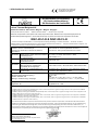
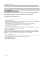
Connections / Anschlüsse / Raccordements / Подключения
Connections / Anschlüsse / Raccordements /
Подключения
Ex i
Ex e
N°: 10-IEx-0020X
Ex e ib mb IIC t* Gb
Ex ib IIIC T* °C Db IP66
Baseefa08ATEX0184X / IECEx BAS 08.0047X
II 2 GD
Ex e m b ib IIC T * Gb (-4 0°C
≤Ta≤+*°C)
*See Table
Ex tb IIIC T * ° C Db IP66 (-40°C
≤Ta≤+*°C)
*See Table
ModBus:
100 - 254 VAC
Operating voltage:
Betriebsspannung:
Tension nominale:
Рабочее напряжение:
TC RU С-ВЕ.ИМ43.В.01764
1Ex e ib mb IIC T5/T4 Gb X
Ex tb IIIC T100°C/T130°C Db X IP66
Ser
ial
number
ins
ide
Ser
iennummer
inn
en
N° de sér i
e à
l’in
t
e
rieu
r
Серийный N° внутри
Lot/Los/Lot/Партии
N°:
Temperature Class / Температурный класс T5 Gb / T95°C Db
Ambient temperature (°C)
Темп. окр. среды (°C)
Maximum switching current (A)
Макс. пусковой ток (A)
Ambient temperature (°C)
Темп. окр. среды (°C)
Maximum switching current (A)
Макс. пусковой ток (A)
–40 to +50
25
Temperature Class / Температурный класс
T4 Gb / T130°C Db
–40 to +54 20
–40 to +56 16
–40 to +56 25
Texte Français dans le manuel technique / Deutsche Texte siehe
Betriebsanleitung /
Подробная техническая информация
приведена в "Инстркции по м
онтажу, эксплуатации и
техническому обслуживанию".
Switch current de-rating table / Tabelle temparatur-
abhängiger Schaltstrom / Tab
leau de dégrèvement
courant de coupure / Таблица значений пускового тока
Leuven, Belgium / Левен, Бельгия
NGC-20-CL-E
PN 1244 -007035
Heat-Tracing Temperature Control Unit
Temperaturregler für Begleitheizungen
Блок управления температурой системы электрообогрева
Unité de Contrôle de Température pour Traçage Electrique
nvent.com
Made in Germany
Installation, Operating and Maintenance Instructions
Installations-, Betriebs- und Wartungsanleitung
Guide d’installation, d’utilisation et de maintenance
Instruções de instalação, operação e manutenção
Инструкции по монтажу, эксплуатации и техническому
обслуживанию
NGC-20-C(L)-E

For English text, go to page 3
Für Deutsch, siehe Seite 21
Pour la version française, voir page 39
Para a versão em português, vá para a págian 57
For RU text, go to page 75
2 | nVent.com

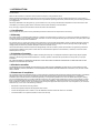
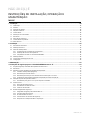
TABLE OF CONTENTS
1. Introduction ............................................................................................................................................ 4
1.1 Certication ..............................................................................................................................................................................................4
1.2 Warranty ....................................................................................................................................................................................................4
1.3 Limitation of warranty ..............................................................................................................................................................................4
1.4 Exclusive remedies ..................................................................................................................................................................................4
1.5 Statement of compliance ........................................................................................................................................................................4
1.6 Declaration of conformity ........................................................................................................................................................................5
1.7 Area of use................................................................................................................................................................................................6
1.8 Safety instructions ...................................................................................................................................................................................6
1.9 Conformity with standards ......................................................................................................................................................................6
1.10 Technical data ..........................................................................................................................................................................................6
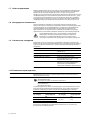
2. Installation ........................................................................................................................................... 11
2.1 Tools required .........................................................................................................................................................................................11
2.2 Mechanical installation ..........................................................................................................................................................................11
2.3 Temperature sensors .............................................................................................................................................................................11
2.3.1 Lead compensation of RTD connections. ................................................................................................................................11
2.3.2 Installation of temperature sensors .......................................................................................................................................... 12
2.3.3 Remote temperatures via nVent RAYCHEM RMM ...................................................................................................................14
2.4 Electrical installation ..............................................................................................................................................................................14
2.5 Communication and networking ...........................................................................................................................................................15
2.6 Conguration ..........................................................................................................................................................................................15
3. Maintenance ......................................................................................................................................... 15
4. Safety instructions for nVent RAYCHEM NGC-20-CL-E .......................................................................... 15
4.1 Safety function of temperature limiter in NGC-20-CL-E .......................................................................................................................15
4.2 Area of use..............................................................................................................................................................................................15
4.3 Requirements to be met by the temperature limiter ............................................................................................................................16
4.3.1 Temperature limiter (schematic)...............................................................................................................................................16
4.3.2 Reset by hand only .....................................................................................................................................................................16
4.3.3 Reset by hand via tool or keyed lock ......................................................................................................................................... 16
4.3.4 Temperature setting secured and locked to prevent manipulation ........................................................................................17
4.4 Changing limiter set point ......................................................................................................................................................................17
4.4.1 Procedure to write new temperature set point to limiter .........................................................................................................17
4.5 Functional test ........................................................................................................................................................................................18
4.5.1 Functional test description ........................................................................................................................................................18
4.5.2 Functional test procedure .......................................................................................................................................................... 18
4.5.3 Test in the event of a fault .........................................................................................................................................................18
4.6 Safety Integrity level ...............................................................................................................................................................................18
4.6.1 Safety integrity of the NGC-20 hardware ..................................................................................................................................19
4.6.2 PFDavg safety function ..............................................................................................................................................................19
4.6.3 SIL related to SFF and HFT ........................................................................................................................................................19
4.6.4 Safety related system characteristics ......................................................................................................................................20
4.6.5 Response in operation and fault conditions .............................................................................................................................20
NGC-20-C(L)-E
INSTALLATION, OPERATING AND MAINTENANCE
INSTRUCTIONS
nVent.com | 3

1. INTRODUCTION
Please read all instructional literature carefully and thoroughly before starting. Refer to the inside front cover for the listing of Liabilities
and Warranties.
NOTICE: The information contained in this document is subject to change without notice.
Please read these Operating Instructions before Commissioning the instrument. Keep the operating instructions in a place which is
accessible to all users at all times. Please assist us to improve these operating instructions, where necessary. We are always grateful for
your suggestions.
Should any diculties arise during start-up, you are asked not to carry out any unauthorized manipulations on the instrument as this
could affect your warranty rights! Please contact the nearest nVent subsidiary or the head oce.
If any servicing is required, the instrument must be returned to the head oce.
1.1 Certification
nVent certies that this product met its published specications at the time of shipment from the Factory.
1.2 Warranty
This nVent product is warranted against defects in material and workmanship for a period of 12 months from the date of installation or
30 months maximum from the date of shipment, whichever occurs rst. During the warranty period, nVent will, at its option, either repair
or replace products that prove to be defective.
For warranty service or repair, this product must be returned to a service facility designated by nVent. The Buyer shall prepay shipping
charges to nVent and nVent shall pay shipping charges to return the product to the Buyer. However, the Buyer shall pay all shipping
charges, duties, and taxes for products returned to nVent from another country.
nVent warrants that the software and rmware designated by nVent for use with a product will execute its programming instructions
properly when installed on that product. nVent does not warrant that the operation of the hardware, or software, or rmware will be
uninterrupted or error-free.
1.3 Limitation of warranty
The foregoing warranty shall not apply to defects resulting from improper or inadequate maintenance by the Buyer, Buyer-supplied
software or interfacing, unauthorized modication or misuse, operation outside of the specications for the product, or improper
installation.
NO OTHER WARRANTY IS EXPRESSED OR IMPLIED. NVENT DISCLAIMS THE IMPLIED WARRANTIES OF MERCHANTABILITY AND
FITNESS FOR A PARTICULAR PURPOSE.
1.4 Exclusive remedies
THE REMEDIES PROVIDED HEREIN ARE THE BUYER’S SOLE AND EXCLUSIVE REMEDIES. NVENT SHALL NOT BE LIABLE FOR ANY
DIRECT, INDIRECT, SPECIAL, INCIDENTAL, OR CONSEQUENTIAL DAMAGES, WHETHER BASED ON CONTRACT, TORT, OR ANY OTHER
LEGAL THEORY.
1.5 Statement of compliance
This equipment has been tested and found to comply with the low voltage directive 2006/95/EC and the electromagnetic compatibility
directive 2004/108/EC. These limits are dened to provide reasonable protection against harmful interference in a residential
installation (technical data mentions industrial application). This equipment generates uses and can radiate radio frequency energy
and, if not installed and used in accordance with the instructions, may cause harmful interference to radio communications. However,
there is no guarantee that interference will not occur in a particular installation. If this equipment does cause harmful interference to
radio or television reception, which can be determined by turning the equipment off and on, the user is encouraged to try to correct the
interference by one or more of the following measures:
• Reorientate or relocate the receiving antenna.
• Increase the separation between the equipment and receiver.
• Connect the equipment into an outlet on a circuit different from that to which the receiver is connected.
• Consult the dealer or an experienced radio/TV technician for help.
4 | nVent.com

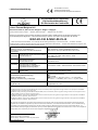
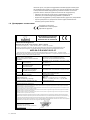
1.6 Declaration of conformity
Our products satisfy
the requirements of the
relevant European Directives.
DoC NGC-20-xx-E rev 3.1 10.1.2019.doc Page 1 of 1
EU Declaration of Conformity
EU Konformitätserklärung
EU Déclaration de Conformité
We / Wir / Nous,
nVent Thermal Belgium N.V.
Romeinse straat 14, 3001 Leuven / Belgium – Belgien - Belgique
Hereby declare that the products… / Erklären, dass die Produkte… / Déclarons, que les produits…
Electronic Temperature control System with Safety temperature limiter: Elektronischer Temperaturregelsysteme mit
Sicherheitstemperatur Begrenzer: / Thermostat électronique: Système avec limiteur de température de sécurité:
NGC-20-C-E & NGC-20-CL-E
…which is the subject of this declaration, is in conformity with the following standard(s) or normative documents / …auf welche sich diese
Erklärung bezieht, mit der/den folgenden Norm(en) oder normativen Dokumenten übereinstimmt / …auxquels cette déclaration se rapporte, sont
conformes aux norme(s) ou aux documents normatifs suivants
Terms of the Directive(s) and Approval Data…
Richtlinien, Normen und Zulassungen…
Prescription de la directive et données de référence
d’approbation…
Title and/or No. and date of issue of the standard /
Titel und/oder Nr. sowie Ausgabedatum der Norm /
Titre et/ou No. ainsi que date d'émission des normes
2014/53/EU
R&TTE Directive- Radio Telecommunications
Terminal Equipment
* EN 301489-1 :V1.9.2, * EN 301489-17, * EN 61000-3-2 :2006
+A1 :2009 + A2 :2009, * EN 61000-3-3 :2008,
* EN 300328 :V1.7.1
2014/35/EU
Low Voltage directive
Niederspannungsrichtlinie
Directive Basse tension
* EN 61010-1:2004, * EN 60730-1:2011, * EN 60730-2-9:2010
* EN 62479 :2010
2014/30/EU
Electromagnetic compatibility
Elektromagnetische Verträglichkeit
Compatibilité électromagnétique
* EN 61000-6-3:2006, * EN 61326:2002, * EN 61000-6-2:2005
2014/34/EU
ATEX Directive / ATEX Richtlinie / La
Directive ATEX
EN 60079-0:2012, * EN 60079-11:2012, EN 60079-18:2009
EN 60079-7:2007, EN 60079-31:2009
EC-Type Examination Certificate /
EG Baumusterprufbescheinigung /
Attestion déxamen CE
Markings / kenzeichnung / marquage
Baseefa08ATEX0184X/4
II 2 GD
Ex e mb ib IIC T * Gb (-40°C ≤ Ta ≤ + * °C) *See Table.
Ex tb IIIC T * °C Db IP66 (-40°C ≤ Ta ≤ + * °C) *See Table.
EC-Type Examination certification body and
Registration Nr;
Baseefa Ltd. Buxton UK
Registration No. 1180
Harmonized standards are marked with (*)
*) EN 60079-0:2012 (A review against EN 60079-0:2017, which is harmonized, shows no significant changes relevant to this equipment so EN 60079-
0:2009 continues to represent “State of the Art”)
*) EN 60079-7:2007 (A review against EN 60079-7:2015/A1:2018, which is harmonized, shows no significant changes relevant to this equipment so EN
60079-7:2007 continues to represent “State of the Art”)
*) EN 60079-18:2009 (A review against EN 60079-0:2015, which is harmonized, shows no significant changes relevant to this equipment so EN 60079-
18:2009 continues to represent “State of the Art”)
*) EN 60079-31:2004 (A review against EN 60079-0:2015, which is harmonized, shows no significant changes relevant to this equipment so EN 60079-
18:2004 continues to represent “State of the Art”)
The technical documentation required to demonstrate that the products meet the requirements of the above EC directives has been
compiled and is available for inspection by relevant enforcement authorities. / Die technische Dokumentation, die zur Gewährleistung
der Einhaltung der EG Richtlinien benötigt wird, wurde erstellt und liegt zur Überprüfung durch eine autorisierte Stelle bereit. / La
documentation technique exigée pour démontrer que les produits répondent aux exigences des directives CE ci-dessus a été compilée et
est disponible pour l'inspection par des autorités chargées de l'application appropriée.
Gerry De Blick
Manager Approvals & Certifications
Leuven January 10th 2019 / Louvain 10 janvier 2019.
nVent.com | 5

1.7 Area of use
NGC-20-C(L)-E controllers are used for temperature control and temperature limiting of electrical heaters in industrial and potentially
explosive atmospheres. The NGC-20-CL-E consists of a temperature controller and an additional safety temperature limiter.
NGC-20-C(L)-E units are approved for use in hazardous area Zone 1 and Zone 2 (Gas) and Zone 21 and Zone 22 (Dust). Where needed
the temperature sensor of the unit can be placed in Zone 0 (Zone 20) However, the control unit itself is not approved for being installed
in Zone 0 (Zone 20).
1.8 Safety instructions
During operation, do not leave this Instruction Manual or other objects inside the enclosure. Use the temperature controller and limiter
only for its intended purpose and operate it only in clean, undamaged condition. In the event of incorrect assembly, the requirements of
IP66 as specied by IEC 60529:2001 are no longer met. Do not make any modications to the temperature controller and limiter that are
not expressly mentioned in this Instruction Manual.
Whenever work is done on the temperature controller and limiter, be sure to observe the national safety and accident prevention
regulations and the safety instructions given in this Instruction Manual.
1.9 Conformity with standards
NGC-20-C(L)-E units meet the requirements of the following Hazardous area- and functional safety standards and are developed,
manufactured and tested in accordance with state-of-the-art engineering practice.
IEC 60079-0, EN60079-0 General requirements
IEC 60079-7, EN60079-7 Increased safety Ex e
IEC 60079-18, EN60079-18 Encapsulation Ex m
IEC 60079-11 EN60079-11 Intrinsic safety Ex i
IEC 61241, EN 61241 Parts 1 to 3 Electrical apparatus for use in the presence of combustible dust
IEC 61508-1:2000 and IEC 61508-2:2000 For NGC-20-CL-E only: Functional Safety of Electrical /Electronic /
Programmable Electronic Safety-related Systems
Table 1: Standards overview.
1.10 Technical data
Application type NGC-20-Cx-E units are approved for use in Hazardous area Zone 1 or Zone 2 (Gas) or Zone
21 or Zone 22 (Dust) and non hazardous areas
Hazardous area Approval
Baseefa08ATEX0184X
II 2 GD Gb Ex e mb ib IIC T* Db Ex tD A21 IP66 T95°C
IECEx BAS 08.0047X
Gb Ex e mb ib IIC T* Db Ex tD A21 IP66 T95°C
T*: The switching capacity depends on the hazardous area temperature classification
(T-Class) and the maximum expected use temperature. Ratings as shown in table below
Temperature Class T5 Temperature Class T4
Maximum Ambient
Temperature
Maximum Switching
Current
Maximum Ambient
Temperature
Maximum
Switching Current
+ 50 °C 25 A
Up to 56 °C 25 A+ 54 °C 20 A
+ 56 °C 16 A
All values as per hazardous area certication.
Current ratings are given for a supply voltage of 254V +/-10%, 50/60 Hz and resistive loads only.
TC RU С-ВЕ.ИМ43.В.01764
1Ex e ib mb IIC T5/T4 Gb X
Ex tb IIIC T100°C/T130°C Db X IP66
Ta -60°C... +60°C
ООО "ТехИмпорт
N°: 10-IEx-0020X
Ex e ib mb IIC T* Gb
Ex tb IIC T* °C Db IP66
6 | nVent.com

Functional Safety Approval Baseefa08SR0134 SIL2
IEC 61508-1:1998 & IEC 61508-2:2000
Special Conditions for Safe Use Cable entry devices shall be suitably certified and maintain the IP66 minimum of the
enclosure. Unused cable entries must be filled with suitable certified stopping plugs.
Not more than one single or multiple strand wiring lead shall be connected into either side
of the terminals.
Leads connected to the terminals shall be insulated for the appropriate voltage and this
insulation shall extend to within 1 mm of the metal of the terminal throat.
When used in dust atmospheres any dust layers occurring shall have a maximum depth of
no greater than 50 mm.
The max permitted current of the Non IS alarm contacts is 3A.
The earth pillar adjacent to the RTD connectors must be used only for RTD cable screens.
The external RTDs must be capable of withstanding a 500V test to earth.
Environmental
Temperature range controller From –200 to +700°C in steps of 1K
Temperature range limiter From –60 to +599°C in steps of 1K (NGC-20-CL-E only)
Ambient operating temperature From –40°C to +50°C in T5 and from –40°C to +56°C in T4
Storage temperature From –55°C to +80°C
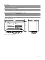
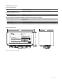
Enclosure NGC-20-C(L)-E units can be installed directly on the pipe via an appropriate support bracket as
long as the maximum permitted ambient temperature is not exceeded. Alternatively, units can
be mounted on any stable structure via the molded holes in the enclosure.
Protection IP66 to IEC-60529
Material Glass fiber reinforced polyester with internal earth plate on the bottom
Installation position Any position allowed, typical use with glands facing down.
Electrical data
Power supply & own power consumption 100 V to 254 V +/-10% 50/60 Hz. 20 VA max.
Connection terminals All cage clamp style connection terminals:
L, N and PE terminals 9 pc (0.2 to 6 mm²)
Alarm output terminals 3 pc (0.2 to 2.5 mm²)
Pt100 (RTD) terminals 12 pc (0.2 to 1.5mm²)
RS-485 communication 7 pc (0.2 to 1.5mm²)
Internal Earth stud 1 pc (Max 6 mm²)
Contact lifetime 500 K operations at 25 A / 254 VAC (resistive load)
Alarm output relay Contact rated 254 VAC / 3A
Relay output is software programmable to open, close or to toggle in case of alarm.
Electromagnetic compatibility EN 61000-6-2:2005 (Gen. Immunity standard for industrial environments)
EN 61000-6-3:2007 (Gen. Emission standard for residential, commercial and light industrial)
EN 61000-3-2-2006 (Limits for harmonic current emissions)
EN 61000-3-3:1995+A1:2001+A2:2005 (limitation of voltage fluctuations and flicker)
Electrical safety EN 61010-1, Category III, Pollution degree 2.
Vibration & Shock Shock to EN 60068-2-27: 1/2 sine wave of 11 ms duration, 15 g
Vibration to EN 60068-2-6 / sine wave 10 to 150 Hz (p-p), 2 g
Temperature sensors
Type 100 Ω platinum, 3-wire, α = 0.00385 Ω/°C. Can be extended with a three core shielded or
braided cable of maximum 20 Ω lead resistance per conductor.
Quantity Two RTD inputs for the controller plus one independent temperature input for the limiter. In
case it is required, more RTDs can be monitored with optional RMM2 units. All temperature
sensors are permanently monitored for “sensor open” and “sensor break”
nVent.com | 7

Communications
Physical network RS-485 and Class 1 Bluetooth
Protocol / topology ModBus RTU or ASCII. Multi drop / Daisy chain
Cable and maximum length Shielded twisted pair cable, 0.5 mm² (AWG 24) or larger. Maximum cable length between
should be no more than 1200 m.
Maximum quantity of controllers in Max. of 247 units per NGC-UIT or per communication port
one network
(ModBus) Network address Software programmable via nVent RAYCHEM NGC-CMA-NH or nVent RAYCHEM NGC-CMA-EX
Programming and setting
Method Through handheld programming device nVent RAYCHEM NGC-CMA2 and a wireless
Bluetooth connection or via RS485 interface and nVent RAYCHEM Supervisor software or
nVent RAYCHEM User Interface Terminal (NGC-UIT-ORD, NGC-UIT-OUT) and customized
nVent RAYCHEM software.
Units of measure °C or °F, software selectable.
Memory Nonvolatile. There is no loss of parameters after the event of power outage or long term
shut down. Data holding time ~10 years.
LED indicators Status LEDS are available for:
NGC-20-C-E Heater, Alarm, RS485 communication, Bluetooth communication
NGC-20-CL-E Heater, Alarm, Limiter (tripped), RS485 communication and Bluetooth.
Measuring ranges
Temperature range controller From –200°C to +700°C in steps of 1K
Temperature range limiter From –60°C to +599°C in steps of 1K (NGC-20-CL-E only)
Voltage From 50 VAC to 305 VAC
Load Current From 0.3 A to 30 A
Ground fault current From 10 mA to 250 mA
Heater Time Alarm From 1 to 1x 10
6
hours
Relay Cycle Alarm From 0 to 2x 10
6
operations
Ordering information
RAYCHEM NGC-20 control units
Product name NGC-20-C-E (Standard temperature control unit)
Part number & (weight) 1244-007035 (3.3 kg.)
Product name NGC-20-CL-E (Temperature control unit with integrated temperature limiter)
Part number & (weight) 1244-007036 (3.4 kg.)
8 | nVent.com

NGC-20 Accessories
Temperature Sensors
Product name MONI-PT100-260/2 (Flexible temp. sensor with measuring range from –50 to 260°C)
Part number & (weight) 1244-006615 (0.09 kg.)
Support Bracket for installation on pipe
Product name SB-125
Part number & (weight) 1244-06603 (0.5 kg.)
Bluetooth enabled handheld programming device with customized software
Product name NGC-CMA-EX (Hazardous area approved device for use in Zone 1 / Zone 21)
Part number & (weight) 1244-006605 (1.2 Kg.)
Product name NGC-CMA-NH (Industrial grade, not approved for use in hazardous area)
Part number & (weight) 1244-006606 (0.8 Kg.)
Table 2: Technical data
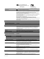
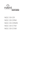
220
120
120
1180
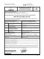
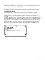
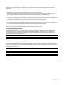
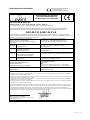
Connections / Anschlüsse / Raccordements / Подключения Connections / Anschlüsse / Raccordements / Подключения
Ex i Ex e
Heat-Tracing Temperature Control Unit with Safety limiter
Temperaturregler mit Sicherheitstemperaturbegrenzer
Блок управления температурой системы электрообогрева
с ограничителем безопасности
Contrôleur/Limiteur de Température pour Traçage Electrique
N°: 10-IEx-0020X
Ex e ib mb IIC t* Gb
Ex ib IIIC T* °C Db IP66
Baseefa08ATEX0184X / IECEx BAS 08.0047X
II 2 GD
Ex e mb ib IIC T * Gb (-40°C
≤Ta≤+*°C) *See Table
Ex tb IIIC T * °C Db IP66 (-40°C
≤Ta≤+*°C) *See Table
ModBus:
100 - 254 VAC
Operating voltage:
Betriebsspannung:
Tension nominale:
Рабочее напряжение:
TC RU С-ВЕ.ИМ43.В.01764
1Ex e ib mb IIC T5/T4 Gb X
Ex tb IIIC T100°C/T130°C Db X IP66
Serial number inside
Seriennummer innen
N° de série à l’interieur
Серийный N° внутри
Lot/Los/Lot/Партии N°:
Temperature Class / Температурный класс T5 Gb / T95°C Db
Ambient temperature (°C)
Темп. окр. среды (°C)
Maximum switching current (A)
Макс. пусковой ток (A)
Ambient temperature (°C)
Темп. окр. среды (°C)
Maximum switching current (A)
Макс. пусковой ток (A)
–40 to +5025
Temperature Class / Температурный класс T4 Gb / T130°C Db
–40 to +5420
–40 to +5616
–40 to +5625
Texte Français dans le manuel technique / Deutsche Texte siehe
Betriebsanleitung / Подробная техническая информация
приведена в "Инстркции по монтажу, эксплуатации и
техническому обслуживанию".
Switch current de-rating table / Tabelle temparatur-
abhängiger Schaltstrom / Tableau de dégrèvement
courant de coupure / Таблица значений пускового тока
Leuven, Belgium / Левен, Бельгия
NGC-20-CL-E
Baseefa08SR0134 SIL2
IEC 61508-1:1998 &
IEC 61508-2:2000
PN 1244-007036
Safety Temperature Limiter according to:
Sicherheitstemperaturbegrenzer nach:
Limiteur de Sécurité selon:
Ограничитель безопасности в соответствии с:
nvent.com
Made in Germany
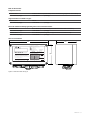
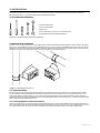
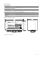
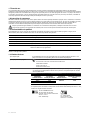
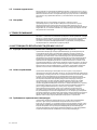
Figure 1: Dimensions NGC-20-C(L)-E
nVent.com | 9

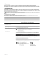
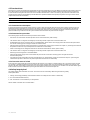
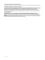
W/B
W/B
R
R
RRPE
L1
N
PE
RS485 cable from
previous device
RS485 cable to
next device
To next NGC-20
Heating cable
PT100
temperature sensor
Only to be used for the LIMITER
PT100
temperature
sensor(s)
RTD 1
RTD 2
RS485
RS485
S
S
+
Li Lo Ni No PE PE PE Lo No
Internal RS485
end of line
termination
resistor
When the device is the last on the communication
line install a wire bridge between the - and
T terminal as shown by the dotted line
Alarm
3A Max
Heater
+
–
–T
PE
RTD LIMITER
RPE
RPE
W/B
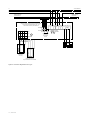
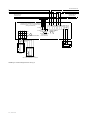
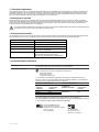
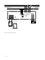
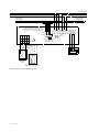
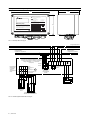
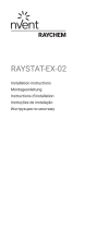
Figure 2: connection diagram NGC-20-C(L)-E
10 | nVent.com

2. INSTALLATION
For installation/operation, always observe the Equipment Safety Law, the rules of generally accepted engineering practice
(IEC60079-14/EN 60079-14), and the instructions stated in this Manual. Carry out work on the thermostats in the de-energized
state only.
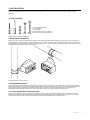
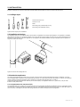
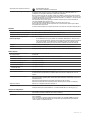
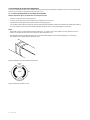
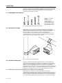
2.1 Tools required
3 mm terminal screwdriver
7 mm screwdriver
Trimming knife
25 mm spanner (for 20 mm glands)
36 mm spanner (for 20/25 adapter)
Figure 3: tools required for installation
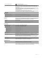
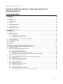
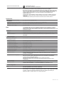
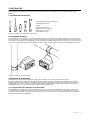
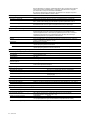
2.2 Mechanical installation
NGC-20-CL-E units comprise a temperature controller and a safety temperature limiter installed in one enclosure. The controllers can
be installed in any position either on a stable structure by means of the 4 mounting holes. Alternatively the NGC-20-C(L)-E units can be
mounted directly on a pipe by means of a support bracket type SB-125. In order to provide enough stability the support bracket needs to
be attached on to the pipe by means of 2 pipe straps.
1180
Connections
/
A
nschlüsse / Rac
corde
m
e
nts / Подключения
Connecti
ons / A
nschlüsse / Raccordements / Подключения
Ex
i
Ex e
Heat-Tracing Temperature Control Unit with Safety limiter
Temperaturregler mit Sicherheitstemperaturbegrenzer
Блок управления температурой системы электрообогрева
с ограничителем безопасности
Contrôleur/Limiteur de Température pour Traçage Electrique
N°: 10-IEx-0020X
Ex e ib mb IIC
t* Gb
Ex ib IIIC T* °C Db IP66
Baseefa08ATEX0184X
/ IECEx BAS
08.0047X
II 2
GD
Ex e mb ib II C T * Gb ( -40°C
≤Ta≤+*°C)
*See Table
Ex tb IIIC T * °C Db IP 66 (-40°C
≤Ta≤+*°C)
*See
T
able
M
odBus:
100 - 254 VAC
Operating voltage:
Betri
ebsspa
nnung:
Tension nominale:
Рабоче
е напряжен
ие:
T
C
RU
С-ВЕ
.ИМ
43.В.017
64
1Ex
e ib mb IIC T5/T4 Gb X
E
x tb IIIC T
1
00°C/T130°C Db X
IP66
Se
r
ial
numbe
r
in
s
ide
S
eri
e
nnummer
innen
N
°
de
série
à
l
’
i
nte
rie
u
r
Сер
ийны
й N° внутри
Lot/Los/Lot/
Партии
N°:
Te
mpera
ture Class / Темп
е
ратурн
ы
й класс T5 Gb / T95°C Db
Ambient temperat
ure (°C
)
Темп
.
окр. среды
(°C)
Maximu
m swi
tch
ing cu
r
rent
(A)
Макс.
пусковой
ток (A)
Ambient temperature (°C)
Темп. окр
.
среды (°C)
Ma
x
i
mum switchin
g
current (A)
Ма
к
с. пусково
й ток (A)
–40
t
o +50 25
Temperatu
re
Cla
ss /
Температурный класс
T4
G
b
/ T13
0°C
D
b
–40 to
+
54 20
–40 to
+
56 16
–40 to +56
2
5
Texte Fra
n
çai
s dans le ma
nu
el te
chnique / Deutsche Te
xte
siehe
Betriebsa
nlei
tung /
Подробная техническая информация
при
веде
на в "Ин
стркции п
о мо
нтажу, эксплуатаци
и
и
техническому обслужи
в
а
ни
ю".
Switch current de-rating table / Ta
belle t
emparatur-
abhängiger Schaltstr
om / Tableau d
e dégrèvement
courant de coupure /
Таблица значений пускового тока
Leu
ven, Belgium / Левен
, Бельгия
NGC-20-C-E
Bas
eefa08SR0134 SIL2
IEC 61508-1:1998 &
IEC 61508-2:2000
PN 124
4-007036
Safety Temperature Limiter ac
cording to:
Sicherheitstemperaturbegrenzer nach:
Limiteur de Sécurité sel
on:
Ограничитель безопасности в соответствии
с:
nvent.com
Made in Germany
1180
Connections / Anschlüsse / Raccordements / Подключения
Connections / Anschlüss
e / Raccor
d
ements /
Подклю
чения
Ex i
Ex e
N°: 10-IEx-0020X
Ex e ib mb IIC t* Gb
Ex ib IIIC T* °C Db IP66
Baseefa08ATEX0184X / IECEx BA
S 08.0047X
II 2 GD
Ex e mb ib II C T * Gb ( -40°C
≤Ta≤+*°C)
*See Tabl
e
Ex tb IIIC T * °C Db IP 66 (-40°C
≤Ta≤+*°C)
*See Table
M
odB
us:
100 - 254 VAC
Operating voltage:
Betriebsspannung:
Tension nominale:
Рабочее напряжение:
TC RU С-ВЕ.
И
М43.В.01764
1Ex
e ib mb IIC T5/T4 Gb X
Ex tb
IIIC T
100°C/T130°C Db X IP66
Se
r
ial num
ber inside
Se
r
ie
nn
u
mme
r
innen
N
° de
s
ér
i
e à l
’inter
i
eur
Се
рийный
N°
внутри
Lot/Los/Lot/Партии
N°:
Temperatur
e Class /
Температурны
й класс T5 Gb / T95°C Db
Ambient t
emper
ature (°C)
Темп. окр. среды (°C)
Maximum switching current
(
A)
Макс. пусково
й ток
(A)
Ambient tempe
r
ature (°C)
Темп. окр. среды (°C)
Maximum switching current (A)
Макс.
пусковой ток (A)
–40 to +50 25
Temperat
ure Class /
Температурный класс
T4 Gb / T130°C Db
–4
0 to +54 20
–4
0 to +56 16
–40 to +56 25
Tex
te Français dans le manuel
tech
ni
que
/ Deutsche Texte
sie
he
Betriebsanleitung /
Подробная техническая
инфо
рмаци
я
приведена в "Ин
стркции по монтажу, э
ксплуатаци
и и
техническому
обслуживанию".
Switch current de-rating table / Tabelle temparatur-
abhängiger Schaltstrom / Tableau de dégrèvement
courant de coupure / Таблица значений пуск
ового тока
Leuven, Belgium / Левен, Бельгия
NGC-20-C-E
PN 1244-00703
5
Heat-Tracing Temperature Control Unit
Temperaturregler für Begleitheizungen
Блок управления температурой системы электрообогрева
Unité de Contrôle de Température pour Traçage Electrique
nvent.com
Made in Germany
Figure 4: Mounting positions NGC-20
2.3 Temperature sensors
The NGC-20C(L)-E temperature inputs are designed as intrinsically safe circuits (IEC 60079-11/EN60079-11 Ex [ib]) therefore any type
of three wire DIN IEC 751 Class B PT100 resistance temperature devices can be used. The NGC-20-CL-E supports 3 local temperature
inputs, where 2 are allocated to the temperature controller (RTD 1 and RTD 2). The third temperature input is reserved for the
temperature limiter (RTD limiter). NGC-20-C-L units on the other hand do not support the third input (RTD limiter)
2.3.1 Lead compensation of RTD connections.
NGC-20-C-E and NGC-20-CL-E units are capable of providing up to 20 Ohm lead resistance compensation. This implies that sensor
connections may be extended using a three core shielded or braided cable with a maximum length of up to 150 meter. (3 x 1.5 mm²
minimum required) The screen or braid of the extension cable is to be grounded at the controllers end only.
nVent.com | 11

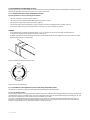
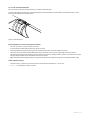
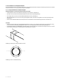
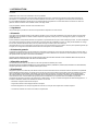
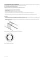
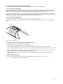
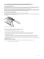
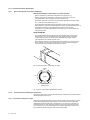
2.3.2 Installation of temperature sensors
The temperature sensors must be installed in such a way that the sensor(s) measure(s) the surface temperature as reliable as possible.
Therefore the guidelines as described in section 2.3.2.1 need to be followed.
2.3.2.1 Temperature sensor of the temperature controller
Important guidelines on sensor positioning and installation:
• The correct position is on top of the pipe. (Figure 2)
• The sensor needs to be attached with sucient glass tape (GT-66 or GS-54).
• Use two bands of glass tape to ensure its position. (Figure 1)
• The lead wire need to leave the insulation so that no moisture can enter the cladding-insulation system. (Figure 2)
• Fix the sensor lead wire to prevent accidental strain on the sensor tip, which could alter its position.
WARNING:
• Do not install sensor at ambient temperatures below –20°C. Do not bend sensor (last 50 mm), keep it straight under all
circumstances. Minimum bending radius for extension cable: 5 mm.
• No metal straps may be used for fastening, because they could damage the sensor when tightened. For this reason the use of bre-
glass self-sticking tapes is recommended.
Figure 5: Mounting temperature sensing on pipe
Sensor
Pipe
Lead entrace
No
No
Figure 6: Sensor and lead entrance
2.3.2.2 Installation of the temperature sensor of the safety temperature Limiter
The NGC-20-CL-E knows two methods of limiting the surface temperature of the heating cable.
2.3.2.2.1 On the pipe surface
The rst method consists of using the surface temperature of the pipe as reference and preventing powering the heating cable when the
pipe temperature is above a calculated value. This value is depended on the make of the cable and the design of the heating circuit. Use
TraceCalc Pro to determine this value and document the calculation in your ling.
The sensor is installed identical to the normal temperature sensor, at the top of the pipe, rmly attached to the surface by means of
glass tape. Special attention needs to be taken that the sensor lead does not cool the pipe/sensor; nor that moisture could enter the
insulation, cooling the sensor tip or reducing the insulation capacity in this area.
12 | nVent.com

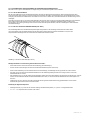
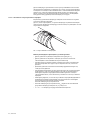
2.3.2.2.2 On an artificial HOT-SPOT
The second way of surface temperature limiting is to create an articial hot-spot.
In order to guarantee the limiter sensor measures the highest possible temperature of the installation, the temperature sensor of the
limiter shall be installed on an articial hotspot.
Figure 7: Articial hot-spot
Important guidelines on sensor positioning and installation:
• The correct position is on top of the pipe. See Figure 7.
• Fix the insulation pad with sucient glass tape. (GT-66 or GS-54)
• Guide the heater from the bottom of the pipe to the insulation pad and x it well so that it keeps its position.
• The sensor needs to be attached with sucient glass tape to the heater. Use two bands of glass tape to ensure its position.
• The lead wire needs to leave the insulation so that no moisture can enter the cladding-insulation system. Fix the lead wire to the pipe
with glass tape if needed to ensure the stability of the hot spot system.
• Make sure that the nominal insulation thickness is respected over the hot spot, it might be necessary to use oversized insulation shells.
Limiter temperature setting:
• The limiter value (T
lim
) needs to be set at the maximum allowed surface temperature (T
max
) minus 10 K.
• T
lim
= T
max
– 10. Temperatures in Kelvin or Celsius.
nVent.com | 13

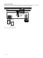
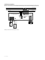
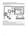
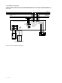
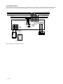
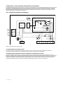
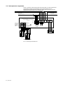
2.4 Electrical installation
Figure 9 shows the electrical connection diagram of the NGC-20 controller. The limiter temperature sensor connection is only applicable
with the NGC-20-CL-E. The optional second Pt100 temperature sensor for the control unit is omitted for clarity.
W/B
W/B
R
R
RRPE
L1
N
PE
RS485 cable from
previous device
RS485 cable to
next device
To next NGC-20
Heating cable
PT100
temperature sensor
Only to be used for the LIMITER
PT100
temperature
sensor(s)
RTD 1
RTD 2
RS485
RS485
S
S
+
Li Lo Ni No PE PE PE Lo No
Internal RS485
end of line
termination
resistor
When the device is the last on the communication
line install a wire bridge between the - and
T terminal as shown by the dotted line
Alarm
3A Max
Heater
+
–
–T
PE
RTD LIMITER
RPE
RPE
W/B
Figure 9: electrical connection diagram NGC-20
14 | nVent.com

2.5 Communication and networking
The NGC-20 controller is equipped with a RS485 interface. Through this interface up to 247 NGC-20 units can be networked to a
NGC-UIT2/TOUCH1500 or to one serial port of standard PC running nVent´ Windows based Supervisor software.
2.6 Configuration
The NGC-20 controllers can be congured locally by means of a handheld programming device (NGC-CMA2) or from a central location
using the NGC-UIT2/TOUCH1500 or Supervisor Software. After programming, all settings are permanently stored in the nonvolatile
memory of the NGC-20 control unit, avoiding loss of data in the event of power failure or after a long term power shutdown.
3. MAINTENANCE
Equipment placed into hazardous areas needs to comply with EN 60079-17 regarding inspection and maintenance requirements. The
EN 60079-17 describes in more detail the requirements regarding documentation, qualications of personnel, inspections, regular
periodic inspections, continuous supervision by skilled persons, maintenance, isolation of apparatus, earthing and inspection schedules.
4. SAFETY INSTRUCTIONS FOR NGC-20-CL-E
4.1 Safety function of temperature limiter in NGC-20-CL-E
The application areas for (safety) temperature limiters can be found anywhere where there are thermal processes to be monitored,
and where the system must be set to a safe operating condition in the event of a fault. If the permitted temperature limit (Temperature
classication) is reached, or a fault occurs within the normal operating temperature (probe break/short-circuit, component defect, power
failure), then the instrument switches to the safe state without delay. If the fault is no longer present, then the safety temperature limiter
must be manually reset. This can be done either by means of the internal reset button inside the unit, The Supervisory Software or the
handheld programming device. The unit will only accept to be reset after the normal operating conditions have returned.
4.2 Area of use
Safety temperature limiters are required in all areas where thermal processes need to be prevented from overheating. In case of a
temperature upset they will put the system into a safe operating condition. The safety function will invoke in the event of a fault, when
the permissible temperature limit is reached or in case a fault occurs (such as probe break, probe short-circuit, component failure, or
supply failure) even when the process conditions are within the permissible temperature range. In all these cases the equipment is
immediately switched off. If the fault is no longer present, than the safety temperature function must be manually reset before the unit
goes back to normal operation. NGC-20-CL-E units can be reset by means of an internal push button or via dedicated software. The
output of the unit will only be enabled when all conditions are safe; meaning that the temperature measured by the limiter RTD has
dropped below the limiter set point and when there are no other faults being detected. In other words, the unit will only reset after the
normal operating conditions have returned.
nVent.com | 15

4.3 Requirements to be met by the temperature limiter
The NGC-20-CL-E safety temperature limiter meets the requirements of IEC 60079-30-1 For applications installed in a hazardous area
Zone 1 (Zone 21) this means that the protective device shall de-energize the system to prevent exceeding the maximum permissible
surface temperature. In case of an error by, or damage to the sensor, the heating system shall be de-energized before replacing the
defective equipment. The protective device operates independently from the temperature controller.
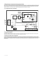
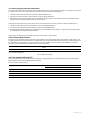
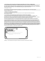
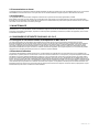
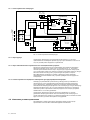
4.3.1 Temperature limiter (schematic)
Reset
Set
Principle limiter analog circuit
Sensor 2
Sensor 1
Limiter
sensor
Temperatue control
Alarm
R485
Alarm relay
..........
..........
..........
..........
..........
..........
LN PE N-load L-load
limiter
relay
ground
fault relay
..........
– 12V
SPI
AND
ground fault
current sensor
load current
current sensor
Temperature -
controller
RTD check
Figure 10: Limiter block diagram.
4.3.2 Reset by hand only
The safety temperature limiter is designed such that after the temperature limiter has tripped the device needs to be reset by hand.
Resetting is possible only after the normal, safe operating conditions have returned.
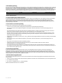
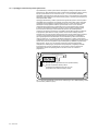
4.3.3 Reset by hand via tool or keyed lock
In order to RESET the limiter after it has tripped, the user needs to press the internal Limiter Reset pushbutton as is shown in Figure 11.
The gure shows where the limiter RESET button is located inside the enclosure (lid removed). Alternatively the safety temperature
limiter can be reset via Supervisor, NGC-UIT2/TOUCH1500 or the handheld conguration and monitoring device NGDC-CMA2 and keying
a specic number on the keyboard. Refer to the operating manual of the specic units for more detailed instructions on how to use
these devices.
16 | nVent.com

4.3.4 Temperature setting secured and locked to prevent manipulation
The lock out temperature (set point) of the safety temperature limiter must be set in such a way that maximum T-class temperature
cannot be exceeded. The surface temperature of the heat-tracing cables is limited to the temperature applicable in this T class -5 K for
temperatures below or equal to 200°C or -10 K for temperatures greater than 200°C. Refer to section 4.4 below for the procedure to
change the safety limiter set point.
Independence from control system
The safety temperature limiter operates totally independent from the temperature control system and has an own temperature
input (RTD Limiter) In case of a defect to any part of the NGC-20 unit the device shall be de-energized before replacing the defective
equipment.
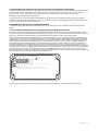
4.4 Changing limiter set point
Changing the set point of the limiter requires the combination of the internal limiter set button and an external user interface.
4.4.1 Procedure to write new temperature set point to limiter
In order to write a new set point to the temperature limiter a safety procedure needs to be followed. Changing the set point of the
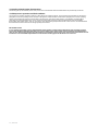
temperature limiter requires the combination of the internal limiter set button as is shown in Figure 11 and a programming device. As
programming device one can use; Supervisor software, NGC-UIT2/TOUCH1500 terminal or the handheld conguration and monitoring
assistant CMA2.
The procedure to change the limiter set point is the same for all user interfaces. The conguration tool will write the new set point to the
input buffer of the NGC-20-CL-E controller. Only when the internal temperature set button is pressed will the new set point be forwarded
to the internal memory of the temperature limiter. The limiter set point button needs to be activated within a certain time after the buffer
has been loaded with the new set point. If the button has not been pressed before the programming window is elapsed, the buffer will
be emptied and the old value remains active. Once the new set point has been written the new or in case the write procedure was not
successful the old set point will be read back by the programming device as conrmation to the user. After changing the limiter set point
the user shall verify whether the set point has been updated correctly. The limiter set point can be shown on the NGC-20 hardware by
pressing and holding the black Limiter SET button. While the limiter set point is shown the red LED indicator marked with LIMITER will
blink. After the button is released the display will show the controllers measured temperature again and the LIMITER LED will go off.
Each time after the limiter set point has been altered a functional test as per paragraph 4.5.1 is to be performed.
HEATER
ALARM
LIMITER
RS485
BLUETOOTH
RESET
LIMITER
SET
nVent RAYCHEM NGC-20
Limiter reset button (rearm the limiter after it has tripped)
Limiter temperature set button to be pressed after
the polling process has been initiated
Figure 11: Internal Limiter control buttons: Limiter (temperature) SET and Limiter RESET pushbuttons.
nVent.com | 17

4.5 Functional test
The NGC-20-CL-E units are meeting the requirements of SIL2 (see paragraph 4.6 for more details) accordingly to IEC 61508-1:2000 and
IEC 61580-2:2000 In this standard is stipulated that in order to guarantee safe and reliable operation the units need to be subjected
to a functional test at regular intervals. In the case of the NGC-20 limiter this is set at 12 months (1 year) intervals. These tests must
be performed according to the guidelines provided. When the operational lifetime has expired, the systems no longer conform to the
requirements of their SIL certication.
Type SIL level Proof check interval Unit Lifetime
NGC-20-CL-E SIL 2 1 year 25 years
Table 3: Functional test
4.5.1 Functional test description
In general the functional test always starts from the “normal” state, meaning that there should not be any alarms present on the unit
and that the limiter tripped LED (Lim Tripped) on the display of the unit should not be lit. In case the Lim Tripped LED is ON than the
unit should be reset before the functional test is being performed. Apart from the scheduled test intervals a functional test is to be
performed after every malfunction of the system and each time the limiter set point has been changed.
4.5.2 Functional test procedure
The following steps should be executed as part of the functional test:
• Disconnect one of the leads of the temperature sensor of the limiter RTD. (RTD 3 limiter)
• The red alarm LED “Lim tripped” should light up momentary and the output of the unit should switch OFF.
• Re-establishing the sensor connection has no immediate effect. Switch off the mains supply of the unit and leave the power off for
one minute. Powering up the unit again should not reset the limiter.
• After the Limiter reset button is been pressed the Lim Tripped alarm will go away and switch the output on. (Assuming the measured
temperature is below the set point temperature and there are no other faults)
• Install a wire bridge, short cutting the limiter sensor terminals marked with R+ and R- (RTD 3 Limiter)
• The red alarm LED “Lim tripped” should light up momentary and the output of the unit should switch OFF.
• Removing the wire bridge has no immediate effect.
• Switch off the mains supply of the unit and leave the power off for one minute. Powering up the unit again should not
reset the safety limiter.
• Only after the Limiter reset button has been pressed will the Lim Tripped alarm go away and switch the output on. (Assuming the
measured temperature is below the set point temperature and there are no other faults)
4.5.3 Test in the event of a fault
In the event of a system fault, the instrument switches off the load. This condition is indicated by the LED “Lim tripped” which will light
up. The fault is signalled simultaneously by the alarm relay which changes state. Press the reset button (at least 2 sec) until the “Lim.
Tripped” LED dims. If the safety circuit remains open, the system and the probe circuit have to be checked. Press the reset button again.
If the instrument remains inhibited after pressing the reset button the unit should be replaced.
4.6 Safety Integrity level
The safety integrity level of the NGC-20 is SIL2. The SIL level can be achieved by determining the following safety
related parameters:
1. PFDavg: The average probability of the hazardous failure of a safety function when it is demanded;
2. HFT: The hardware fault tolerance;
3. SFF: The fraction of non-hazardous (i.e. safe) failures
See for details on the NGC-20-CL-E table Table 4.
18 | nVent.com

4.6.1 Safety integrity of the NGC-20 hardware
According to IEC 61508-2:2000, a distinction must be made between Type A systems and type B systems. A sub-system can be viewed
as a Type A system if, for the components that are necessary in order to achieve the safety function:
1. The failure mode of all components that are used is adequately dened, and
2. The response of the sub-system in fault conditions can be completely determined,
3. Reliable failure data based on eld experience are available for the sub-system, to demonstrate that the assumed failure rates for
recognized and unrecognized hazardous failures can be achieved.
A sub-system can be viewed as a Type B system if, for the components that are necessary in order to achieve the safety function:
1. The failure mode of at least one component that is used is not adequately dened, or
2. The response of the sub-system in fault conditions cannot be completely determined, or
3. No adequately reliable failure data based on eld experience are available for the sub-system, to support the assumed failure rates
for recognized and unrecognized hazardous failures.
The NGC-20-CL-E temperature control system with limiter corresponds to a Type A system.
4.6.2 PFDavg safety function
The limiter sensor, limiter electronics and the limiter relay together form the safety related system that performs a safety function. The
“average probability of the hazardous failure of a safety function for the entire safety-related system” (PFDavg) is usually divided among
the subsystems. An external device e.g. an external power contactor installed in a panel, is specic to the installation, and shall, in
accordance with the standards for the safety loop, be considered separately.
Type SIL level Architecture Proof check
interval
MTTR (hrs) PFD avg. HTF SFF
NGC-20-CL-E
SIL 2 1oo1D 1 year 24 3.017E-3 0 (1oo1) 95.03%
Table 4: Safety Integrity level
MTTR = Mean time to repair
4.6.3 SIL related to SFF and HFT
The following table presents the achievable safety integrity level (SIL), depending on the safe failure fraction (SFF) and the hardware
failure tolerance (HFT) for Type A safety-related sub-systems.
Table 5 is valid for the NGC-20-CL-E:
Safe failure fraction (SFF) Hardware fault tolerance (HFT) for Type A
0 1 2
SFF < 60% SIL 1 SIL 2 SIL 3
60 < SFF < 90 % SIL 2 SIL 3 SIL 4
90% < SFF < 99% SIL 3 SIL 4 SIL 4
99% < SFF SIL 3 SIL 4 SIL 4
Table 5: Relation SFF to HFT
nVent.com | 19

4.6.4 Safety related system characteristics
The failure types of; sensor break, sensor short, sensor misconnected and random hardware failure are permanently monitored.
4.6.5 Response in operation and fault conditions
The response in operation and fault conditions is described in the operating manual. The necessary functional tests are described in
paragraph 4.5.3 of this operating manual. The test to be applied in a fault condition is described in paragraph 4.5.2 of this operating
manual. A functional test must be carried out after commissioning, repair to the safety system, or an alteration of safety-related
parameters. If a fault is detected in the course of a functional test, then measures must be implemented to restore the reliable
functionality of the safety system. This can, for instance, be achieved through replacement of the control unit. It is recommended that
the tests that have been carried out are all appropriately documented.
IMPORTANT NOTICE
In case a failure of the safety system is detected either during operation or during routine maintenance when executing a function
test the unit should be switched off and taken out of service. Defects in the safety system cannot be repaired in the eld. Defective
units are to be replaced and returned to the manufacturer for investigation. Please contact your nearest nVent representative for more
instructions. A list of worldwide representations can be found on the last page of this document or on nvent.com
20 | nVent.com
La page est en cours de chargement...
La page est en cours de chargement...
La page est en cours de chargement...
La page est en cours de chargement...
La page est en cours de chargement...
La page est en cours de chargement...
La page est en cours de chargement...
La page est en cours de chargement...
La page est en cours de chargement...
La page est en cours de chargement...
La page est en cours de chargement...
La page est en cours de chargement...
La page est en cours de chargement...
La page est en cours de chargement...
La page est en cours de chargement...
La page est en cours de chargement...
La page est en cours de chargement...
La page est en cours de chargement...
La page est en cours de chargement...
La page est en cours de chargement...
La page est en cours de chargement...
La page est en cours de chargement...
La page est en cours de chargement...
La page est en cours de chargement...
La page est en cours de chargement...
La page est en cours de chargement...
La page est en cours de chargement...
La page est en cours de chargement...
La page est en cours de chargement...
La page est en cours de chargement...
La page est en cours de chargement...
La page est en cours de chargement...
La page est en cours de chargement...
La page est en cours de chargement...
La page est en cours de chargement...
La page est en cours de chargement...
La page est en cours de chargement...
La page est en cours de chargement...
La page est en cours de chargement...
La page est en cours de chargement...
La page est en cours de chargement...
La page est en cours de chargement...
La page est en cours de chargement...
La page est en cours de chargement...
La page est en cours de chargement...
La page est en cours de chargement...
La page est en cours de chargement...
La page est en cours de chargement...
La page est en cours de chargement...
La page est en cours de chargement...
La page est en cours de chargement...
La page est en cours de chargement...
La page est en cours de chargement...
La page est en cours de chargement...
La page est en cours de chargement...
La page est en cours de chargement...
La page est en cours de chargement...
La page est en cours de chargement...
La page est en cours de chargement...
La page est en cours de chargement...
La page est en cours de chargement...
La page est en cours de chargement...
La page est en cours de chargement...
La page est en cours de chargement...
La page est en cours de chargement...
La page est en cours de chargement...
La page est en cours de chargement...
La page est en cours de chargement...
La page est en cours de chargement...
La page est en cours de chargement...
La page est en cours de chargement...
La page est en cours de chargement...
-
 1
1
-
 2
2
-
 3
3
-
 4
4
-
 5
5
-
 6
6
-
 7
7
-
 8
8
-
 9
9
-
 10
10
-
 11
11
-
 12
12
-
 13
13
-
 14
14
-
 15
15
-
 16
16
-
 17
17
-
 18
18
-
 19
19
-
 20
20
-
 21
21
-
 22
22
-
 23
23
-
 24
24
-
 25
25
-
 26
26
-
 27
27
-
 28
28
-
 29
29
-
 30
30
-
 31
31
-
 32
32
-
 33
33
-
 34
34
-
 35
35
-
 36
36
-
 37
37
-
 38
38
-
 39
39
-
 40
40
-
 41
41
-
 42
42
-
 43
43
-
 44
44
-
 45
45
-
 46
46
-
 47
47
-
 48
48
-
 49
49
-
 50
50
-
 51
51
-
 52
52
-
 53
53
-
 54
54
-
 55
55
-
 56
56
-
 57
57
-
 58
58
-
 59
59
-
 60
60
-
 61
61
-
 62
62
-
 63
63
-
 64
64
-
 65
65
-
 66
66
-
 67
67
-
 68
68
-
 69
69
-
 70
70
-
 71
71
-
 72
72
-
 73
73
-
 74
74
-
 75
75
-
 76
76
-
 77
77
-
 78
78
-
 79
79
-
 80
80
-
 81
81
-
 82
82
-
 83
83
-
 84
84
-
 85
85
-
 86
86
-
 87
87
-
 88
88
-
 89
89
-
 90
90
-
 91
91
-
 92
92


Raychem NGC-20-C(L)-E Guide d'installation
- Taper
- Guide d'installation
dans d''autres langues
- Deutsch: Raychem NGC-20-C(L)-E Installationsanleitung
- português: Raychem NGC-20-C(L)-E Guia de instalação
Documents connexes
-
Raychem Moni-PT100-NH Guide d'installation
-
-
-
-
-
-
-
Raychem Raychem ETS-05-L2-EP Guide d'installation
-
Raychem NGC-40-SLIM Guide d'installation
-
Autres documents
-
nVent RAYCHEM AT-TS-13 Manuel utilisateur
-
 nVent RAYCHEM RMM2-E Mode d'emploi
-
Sony CMA-D2 Mode d'emploi
-
 nVent RAYCHEM NGC-30-CR Controller Board Manuel utilisateur
-
 nVent RAYCHEM RAYSTAT-EX-02 Mechanical Thermostat Guide d'installation
-
BriskHeat SDCE Manuel utilisateur
-
Dwyer Series TTE Manuel utilisateur
-
Waeco MOBITRONIC RV-RMM-70 Le manuel du propriétaire
-
Chalmit lighting NexLED Guide d'installation
-


