
IDE
MANUALE TECNICO
Aeroevaporatori a soffitto
serie industriale a doppio flusso
BETRIEBSANLEITUNG
Doppeltausblasende
Industrieverdampfer
TECHNICAL MANUAL
Dual discharge industrial range
ceiling unit coolers
MANUAL TECNICO
Aeroevaporadores de techo
serie industrial doble flujo
MANUEL TECHNIQUE
Evaporateurs plafonniers
série industrielle double flux
ТЕХНИЧЕСКОЕ РУКОВОДСТВО
Потолочные воздухоохладители
промышленная серия с двойным потоком

Indice
- Avvertenze
. . . . . . . . . . . . . . . . . . . . . . . . . . . . . . . . . . . . . . . . . . . . . . . . . . . . . . . . . . . . . . . . . . . .1
- Ispezione - Trasporto
. . . . . . . . . . . . . . . . . . . . . . . . . . . . . . . . . . . . . . . . . . . . . . . . . . . . . . .1
- Condizioni da verificare per una corretta
messa in opera
. . . . . . . . . . . . . . . . . . . . . . . . . . . . . . . . . . . . . . . . . . . . . . . . . . . . . . . . . . . . . . .1
- Manutenzione generale
. . . . . . . . . . . . . . . . . . . . . . . . . . . . . . . . . . . . . . . . . . . . . . . . . . . .1
- Avvertenze per una corretta installazione
. . . . . . . . . . . . . . . . . . . . . . . . . . . .1
- Caratteristiche costruttive e dimensionali
. . . . . . . . . . . . . . . . . . . . . . . . . . . . .2
- Suggerimenti per un corretto accesso
all’apparecchio
. . . . . . . . . . . . . . . . . . . . . . . . . . . . . . . . . . . . . . . . . . . . . . . . . . . . . . . . . . . . . . .3
- Schema di collegamento e assorbimento
dei motoventilatori
. . . . . . . . . . . . . . . . . . . . . . . . . . . . . . . . . . . . . . . . . . . . . . . . . . . . . . . . . . .3
- Schema di collegamento e potenze
delle resistenze elettriche
. . . . . . . . . . . . . . . . . . . . . . . . . . . . . . . . . . . . . . . . . . . . .4 - 5
Index
- Hinweise für eine korrekte Inbetriebnahme
. . . . . . . . . . . . . . . . . . . . . . . . . .6
- Allgemeine Wartung
. . . . . . . . . . . . . . . . . . . . . . . . . . . . . . . . . . . . . . . . . . . . . . . . . . . . . . . .6
- Hinweise für eine korrekte Aufstellung
. . . . . . . . . . . . . . . . . . . . . . . . . . . . . . . .6
- Konstruktionseigenschaften
und Abmessungen
. . . . . . . . . . . . . . . . . . . . . . . . . . . . . . . . . . . . . . . . . . . . . . . . . . . . . . . . . .7
- Ratschläge für einen korrekten Zugang
zum Gerät
. . . . . . . . . . . . . . . . . . . . . . . . . . . . . . . . . . . . . . . . . . . . . . . . . . . . . . . . . . . . . . . . . . . . .8
- Anschlußplan und Stromaufnahme der
Motorventilatoren
. . . . . . . . . . . . . . . . . . . . . . . . . . . . . . . . . . . . . . . . . . . . . . . . . . . . . . . . . . . .8
- Anschlußplan und Leistungen der Heizstäbe
. . . . . . . . . . . . . . . . . . .9 -10
Index
- For a correct installation
. . . . . . . . . . . . . . . . . . . . . . . . . . . . . . . . . . . . . . . . . . . . . . . . .11
- Routine maintenance
. . . . . . . . . . . . . . . . . . . . . . . . . . . . . . . . . . . . . . . . . . . . . . . . . . . . .11
- Instructions for a correct installation
. . . . . . . . . . . . . . . . . . . . . . . . . . . . . . . . . .11
- Manufacturing and dimensional features
. . . . . . . . . . . . . . . . . . . . . . . . . . .12
- Proper access to model
. . . . . . . . . . . . . . . . . . . . . . . . . . . . . . . . . . . . . . . . . . . . . . . . . .13
- Connection scheme and fan motor absorption
. . . . . . . . . . . . . . . . . . . .13
- Electric heater connection schemes
and electric power
. . . . . . . . . . . . . . . . . . . . . . . . . . . . . . . . . . . . . . . . . . . . . . . . . . .14 - 15
Indice
- Condiciones a verificar para una correcta
puesta en marcha
. . . . . . . . . . . . . . . . . . . . . . . . . . . . . . . . . . . . . . . . . . . . . . . . . . . . . . . . .16
- Manutención general
. . . . . . . . . . . . . . . . . . . . . . . . . . . . . . . . . . . . . . . . . . . . . . . . . . . . .16
- Advertencias para una correcta instalación
. . . . . . . . . . . . . . . . . . . . . . . .16
- Caracteristicas constructivas y
dimensionales
. . . . . . . . . . . . . . . . . . . . . . . . . . . . . . . . . . . . . . . . . . . . . . . . . . . . . . . . . . . . . .17
- Sujerencias para un correcto acceso
al aparato
. . . . . . . . . . . . . . . . . . . . . . . . . . . . . . . . . . . . . . . . . . . . . . . . . . . . . . . . . . . . . . . . . . . .18
- Esquema de conexión y absorción
motoventiladores
. . . . . . . . . . . . . . . . . . . . . . . . . . . . . . . . . . . . . . . . . . . . . . . . . . . . . . . . . . .18
- Esquema de conexión y potencia
de las resistencias eléctricas
. . . . . . . . . . . . . . . . . . . . . . . . . . . . . . . . . . . . .19 - 20
Index
- Conditions à vérifier pour une installation
correcte
. . . . . . . . . . . . . . . . . . . . . . . . . . . . . . . . . . . . . . . . . . . . . . . . . . . . . . . . . . . . . . . . . . . . . . .21
- Entretien général
. . . . . . . . . . . . . . . . . . . . . . . . . . . . . . . . . . . . . . . . . . . . . . . . . . . . . . . . . . .21
- Instructions pour une installation correcte
. . . . . . . . . . . . . . . . . . . . . . . . . .21
- Caractéristiques constructives
et dimensionnelles
. . . . . . . . . . . . . . . . . . . . . . . . . . . . . . . . . . . . . . . . . . . . . . . . . . . . . . . .22
- Suggestions pour un accès correct à l’appareil
. . . . . . . . . . . . . . . . . . .23
- Schéma de connexion et absorptions
motoventiateurs
. . . . . . . . . . . . . . . . . . . . . . . . . . . . . . . . . . . . . . . . . . . . . . . . . . . . . . . . . . . .23
- Schéma de connexion et puissances
des résistances électriques
. . . . . . . . . . . . . . . . . . . . . . . . . . . . . . . . . . . . . . .24 - 25
Содержание
- Меры предосторожности
. . . . . . . . . . . . . . . . . . . . . . . . . . . . . . . . . . . . . . . . . . . . .26
- Осмотр - Транспортировка
. . . . . . . . . . . . . . . . . . . . . . . . . . . . . . . . . . . . . . . . . . .26
- Условия для выполнения корректного
ввода в эксплуатацию
. . . . . . . . . . . . . . . . . . . . . . . . . . . . . . . . . . . . . . . . . . . . . . . . .26
- Общее техобслуживание
. . . . . . . . . . . . . . . . . . . . . . . . . . . . . . . . . . . . . . . . . . . . . .26
- Меры предосторожности
для корректной установки
. . . . . . . . . . . . . . . . . . . . . . . . . . . . . . . . . . . . . . . . . . .26
- Конструктивные
и пространственные характеристики
. . . . . . . . . . . . . . . . . . . . . . . . . . . .27
- Рекомендации по корректному доступу к аппарату
. . . . . . . .28
- Схема подключения
и потребления мотовентиляторов
. . . . . . . . . . . . . . . . . . . . . . . . . . . . . . . . .28
- Схема подключений и мощностей
электрических ТЭНов
. . . . . . . . . . . . . . . . . . . . . . . . . . . . . . . . . . . . . . . . . . . .29 - 30
Index

Italiano
1
www.modine.com
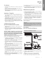
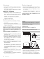
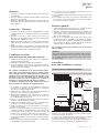
Avvertenze
per una corretta installazione
1. Togliere il coperchio dell’imballo prima di sollevare il modello.
2. Predisporre i tiranti sul soffitto.
3. Sollevare il gruppo modello-imballo fino ad appoggiarlo al sof-
fitto.
4. Avvitare fino in fondo i dadi “A” sui tiranti di fissaggio.
5. Togliere le viti di sicurezza “B” e calare l’imballo vuoto.
6. Serrare i dadi “A” di fissaggio dell’apparecchio al soffitto.
Istruzioni per l’installazione a soffitto
Imballo
Tirante
Imballo
Coperchio imballo
Staffa
Apparecchio
Avvertenze
1. Conservare questo manuale tecnico per tutto il periodo di vita
del modello.
2. Leggere con attenzione il manuale prima dell’installazione e
prima di qualsiasi operazione sul modello.
3. Impiegare il modello esclusivamente per lo scopo per cui é
stato progettato: l’uso improprio esonera il costruttore da qual-
siasi responsabilità.
Ispezione - Trasporto
1. Al ricevimento del modello controllare immediatamente il suo
stato; contestare subito alla compagnia di trasporto qualsiasi
eventuale danno.
2. Durante il trasporto evitare di esercitare pressioni improprie
sull’imballaggio, che va mantenuto comunque sempre nella
posizione indicata sullo stesso.
3. Disimballare il modello il più vicino possibile al luogo di instal-
lazione. Una volta disimballato, evitare urti ai componenti.
4. Durante l’installazione e la movimentazione del modello utiliz-
zare appositi guanti protettivi per evitare di ferirsi con le parti
taglienti (es. alette) del modello.
Condizioni da verificare
per una corretta messa in opera
1. Verificare la tenuta delle strutture di sostegno rispetto al peso
dell’apparecchio.
2. Verificare che il modello venga installato orizzontalmente.
3. Assicurare un volume libero adeguato (circa il 30% del volume
interno della cella) per una corretta circolazione dell’aria in
aspirazione e scarico.
Particolari condizioni di installazione o funzionamento quali
celle basse, travature a soffitto, stoccaggi eccessivi, impedi-
menti al getto e/o all’aspirazione dell’aria, formazione impro-
pria di brina dovuta ad eccessiva immissione di umidità
nella cella, possono influenzare negativamente le prestazioni
dichiarate e creare difettosità nei modelli.
I modelli standard possono non essere adatti ad operare in
tunnel o celle di abbattimento/surgelamento rapido.
4. I modelli sono equipaggiati con motoventilatori assiali, quindi
non adatti ad essere canalizzati o comunque a sopportare
prevalenze statiche aggiuntive.
5. Verificare che le condizioni di funzionamento (temperature e
pressioni) siano conformi a quelle di progetto.
6. Prestare particolare cura in fase di collegamento affinchè non
si deformino i capillari e non si modifichi la posizione del distri-
butore.
7. In caso di più modelli installati a breve distanza l’uno dall’altro,
evitare sbrinamenti alternati.
8. Installare sugli scarichi condensa gli opportuni sifoni e verifi-
carne l'efficacia in tutte le temperature di utilizzo.
9. Evitare l'installazione degli aeroevaporatori vicino alle porte
delle celle.
10.Collocare la sonda di temperatura per il fine sbrinamento nelle
zone più fredde degli scambiatori, ovvero quelle zone che ten-
dono a ghiacciarsi maggiormente (al termine del ciclo non
deve rimanere ghiaccio sui modelli).
La posizione di questo dispositivo non può essere definita a
priori, in quanto varia in relazione al tipo di cella e al tipo di
impianto.
11.Verificare che la linea elettrica di alimentazione sia adeguata
alle caratteristiche elettriche dell’apparecchio.
12.Assicurarsi che tutti i collegamenti elettrici siano in accordo
con le norme vigenti.
13.Ad installazione completata rimuovere la pellicola protettiva
che ricopre il modello.
14.L’accessibilità al modello, per qualsiasi tipo di intervento, deve
essere riservata al personale qualificato alla conduzione del-
l’impianto, secondo le norme vigenti.
Manutenzione generale
1. Verificare periodicamente i fissaggi, le connessioni elettriche e
i collegamenti all’impianto frigorifero.
2. Provvedere alla pulizia periodica dell’apparecchio, per evitare
accumuli di sostanze nocive. Si consiglia l’utilizzo di normale
acqua saponata, evitando solventi, agenti aggressivi, abrasivi
o a base di ammoniaca.
3. In caso di sostituzioni di resistenze elettriche prestare partico-
lare attenzione nelle fasi di installazione per evitare danni alle
vulcanizzazioni; ripristinare correttamente i collegamenti e i
sistemi di fissaggio esistenti per evitare movimenti delle stes-
se durante il funzionamento.
Tali operazioni dovranno essere effettuate da personale
esperto e qualificato.
Attenzione
Prima di effettuare qualsiasi intervento di manutenzione,
accertarsi che l’alimentazione elettrica sia scollegata dalla
fonte principale: le parti elettriche potrebbero essere collegate
ad un controllo automatico.

2
www.modine.com
X
X
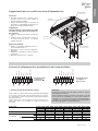
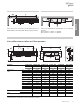
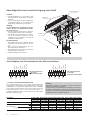
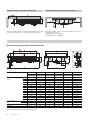
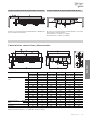
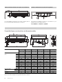
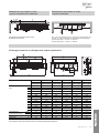
Caratteristiche costruttive e dimensionali
Modello IDE 41A04 41B04 42A04 42B04 43A04 43B04 52A04 52B04 53A04 53B07 54A04 54B04
41A07 41B07 42A07 42B07 43A07 43B07 52A07 52B07 53A07 53B07 54A07 54B07
41A10 41B10 42A10 42B10 43A10 43B10 52A10 52B10 53A10 53B10 54A10 54B10
Dimensioni A 1300 2150 3000 2760 3860 4960
(mm) B 814 1664 2514 2164 3264 4364
C/ / 1700 1100 2 x 1100 3 x 1100
D/ / 814 1064 1064 1064
E 406 410 415 538 543 550
F 400 400 400 530 530 530
G 85 85 85 90 90 90
H 243 243 243 298 298 298
L 1594 1594 1594 1809 1809 1809
M 1449 1449 1449 1664 1664 1664
N 1290 1290 1290 1505 1505 1505
P 280 280 280 280 280 280
Q 490 490 490 680 680 680
R 695 695 695 835 835 835
Attacchi interni batteria entrata 16 22 28 28 35 35
(mm) uscita 35 42 42 54 54 70
Attacco scarico 2 x 1” GAS 2 x 1” GAS 2 x 1” GAS 2 x 2” GAS 2 x 2” GAS 2 x 2” GAS
Peso (kg) 80 145 206 250 370 498
Impiegare valvola termostatica con equalizzatore di pressione esterno.
Distanza minima laterale dalla parete lato resistenze
Distanza consigliata dalle pareti lato uscita aria
In fase di installazione rispettare la quota minima B + 300 mm per poter
togliere/inserire le resistenze.
In fase di installazione si consiglia di rispettare la quota minima “Y”
per garantire una buona circolazione dell’aria:
motoventilatori ø = 450 mm: Y = 700 mm;
motoventilatori ø = 560 mm: Y = 900 mm.

Italiano
3
www.modine.com
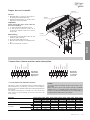
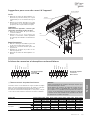
Modello IDE 41A04 41B04 42A04 42B04 43A04 43B04 52A04 52B04 53A04 53B07 54A04 54B04
41A07 41B07 42A07 42B07 43A07 43B07 52A07 52B07 53A07 53B07 54A07 54B07
41A10 41B10 42A10 42B10 43A10 43B10 52A10 52B10 53A10 53B10 54A10 54B10
Motoventilatori n.x ø mm 1x450 2x450 3x450 2x560 3x560 4x560
A 0,79 1,58 2,37 3,3 4,95 6,6
W 430 860 1290 1680 2520 3360
A 0,53 1,06 1,59 2,1 3,15 4,2
W 330 660 990 1280 1920 2560
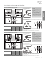
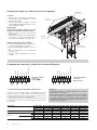
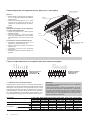
Suggerimenti per un corretto accesso all’apparecchio
Accesso
1. Smontare i tubi di scarico condensa e posi-
zionarli in modo che non creino intralcio al
movimento delle vaschette.
2. Svitare i pomelli di fissaggio “A” per aprire le
vaschette; accompagnarle lentamente fino
alla posizione rappresentata in figura.
Importante:
prima di effettuare l’apertura delle vaschette
accertarsi che siano libere da eventuali resi-
dui di ghiaccio.
3. Svitare i pomelli “B” per aprire i coperchi late-
rali.
4. Svitare le viti “C” per rimuovere i motori; se
necessario rimuovere anche i convogliatori
svitando le viti “D”.
Riposizionamento
1. Fissare i convogliatori mediante le viti “D” e i
motori mediante le viti “C”.
2. Chiudere i coperchi laterali mediante i
pomelli “B”.
3. Rimettere le vaschette in posizione serrando
i pomelli “A”.
4. Rimontare i tubi di scarico condensa.
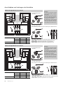
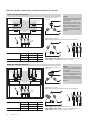
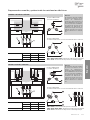
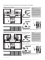
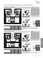
Schema di collegamento e assorbimento dei motoventilatori
(*) Termocontatti di protezione interni
I termocontatti sono elementi di azionamento dipendenti dalla temperatu-
ra che vengono inseriti, isolati, negli avvolgimenti dei motori; essi aprono
un contatto elettrico quando viene superata la temperatura permanente
massima ammissibile.
I termocontatti devono essere collegati ai circuiti di comando dei con-
tatori di modo che in caso di disturbi non si abbia una reinserzione
automatica.
400 V/50 Hz Trifase
collegamento
q
Alta velocità
400 V/50 Hz Trifase
collegamento Y
Bassa velocità
Coperchi laterali
Sostegni
Vaschetta
Convogliatore
Arancio
Marrone
Rosso
Blu
Grigio
Nero
Giallo / vede
Arancio
Marrone
Rosso
Blu
Grigio
Nero
Giallo / vede
Assorbimenti
Alta velocità (∆)
Bassa velocità (Y)
Attenzione
Seguire rigorosamente gli schemi elettrici riportati per evitare il
danneggiamento del motore.
Prima di utilizzare sistemi di regolazione del numero di giri dei
motori verificare la compatibilità con i motori stessi, sistemi non
compatibili possono generare rumorosità e danneggiamenti; il
costruttore. non si assume responsabilità alcuna sulle prestazioni
dei modelli equipaggiati con sistemi di regolazione.

4
www.modine.com
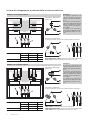
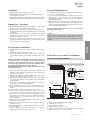
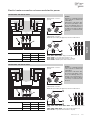
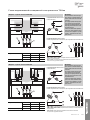
Schemi di collegamento e potenze delle resistenze elettriche
Collegamento 400V/3/50 Hz
(predisposto).
RBA1 / RBA2 / RBA3 / RBA4 - Resistenze di alta potenza nella batteria.
RSA1 / RSA2 - Resistenze di alta potenza sullo sgocciolatoio.
Modello con ventola ø 450 mm
Collegamento 230V3/50 Hz
Si ottiene modificando la disposizione delle barrette in morsettiera.
Modelli IDE ø 450 41A04 42A04 43A04
41A07 42A07 43A07
41A10 42A10 43A10
Potenza totale (W) 5040 10200 15000
Modello con ventola ø 450 mm
Collegamento 400V/3/50 Hz
(predisposto).
RBA1 / RBA2 - Resistenze di alta potenza nella batteria.
RBB1 / RBB2 / RBB3 / RBB4 - Resistenze di bassa potenza nella batteria.
RSA1 / RSA2 - Resistenze di alta potenza sullo sgocciolatoio.
Collegamento 230V3/50 Hz
Si ottiene modificando la disposizione delle barrette in morsettiera.
Modelli IDE ø 450 41B04 42B04 43B04
41B07 42B07 43B07
41B10 42B10 43B10
Potenza totale (W) 5040 10200 15000
Attenzione
È d’obbligo l’applicazione di
opportuni sistemi di protezione
termica sulle linee di alimenta-
zione.
Provvedere periodicamente
alla verifica delle funzionalità di
tutte le resistenze per evitare
accumuli dannosi di ghiaccio
sui modelli.
Il costruttore non risponde in
alcun modo di difettosità create
da malfunzionamenti non rile-
vati.

Italiano
5
www.modine.com
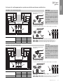
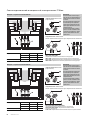
Schemi di collegamento e potenze delle resistenze elettriche
Collegamento 400V/3/50 Hz
(predisposto).
RBA1 / RBA2 / RBA3 / RBA4 - Resistenze di alta potenza nella batteria.
RBB1 / RBB2 - Resistenze di bassa potenza nella batteria.
RSB1 / RSB2 - Resistenze di bassa potenza sullo sgocciolatoio.
RBM1 / RBM2 - Resistenze di media potenza nella batteria.
Modello con ventola ø 560 mm
Collegamento 230V3/50 Hz
Si ottiene modificando la disposizione delle barrette in morsettiera.
Modelli IDE ø 560 52A04 53A04 54A04
52A07 53A07 54A07
52A10 53A10 54A10
Potenza totale (W) 16050 24000 32250
Modello con ventola ø 560 mm
Collegamento 400V/3/50 Hz
(predisposto).
RBA1 / RBA2 / RBA3 / RBA4 / RBA5 / RBA6 - Resistenze di alta potenza
nella batteria.
RBB1 / RBB2 / RBB3 / RBB4 - Resistenze di bassa potenza nella batteria.
RSB1 / RSB2 - Resistenze di bassa potenza sullo sgocciolatoio.
Collegamento 230V3/50 Hz
Si ottiene modificando la disposizione delle barrette in morsettiera.
Modelli IDE ø 560 52B04 53B04 54B04
52B07 53B07 54B07
52B10 53B10 54B10
Potenza totale (W) 19260 28800 38700
Attenzione
È d’obbligo l’applicazione di
opportuni sistemi di protezione
termica sulle linee di alimenta-
zione.
Provvedere periodicamente
alla verifica delle funzionalità di
tutte le resistenze per evitare
accumuli dannosi di ghiaccio
sui modelli.
Il costruttore non risponde in
alcun modo di difettosità create
da malfunzionamenti non rile-
vati.

6
www.modine.com
Hinweise für eine korrekte Aufstellung
1. Vor dem Heben des Modells Verpackungsdeckel abnehmen.
2. Befestigungsschrauben an der Decke vorbereiten.
3. Gerät mit der Verpackung an die Decke heben.
4. Die Muttern “A” an die Befestigungsschrauben fest anziehen.
5. Die Sicherheitsschrauben “B” abnehmen und die leere
Verpackung herunterziehen.
6. Die Befestigungsmuttern “A” des Geräts an die Decke fest
anziehen.
Anweisungen für Wandmontage
Verpackung
Befestigungs-
schraube
Verpackung
Verpackungsdeckel
Halterung
Verdampfer
Hinweise
1. Diese Betriebsanleitung während der ganzen Lebensdauer
des Geräts aufbewahren.
2. Vor Inbetriebnahme des Geräts und vor jedem Eingriff auf-
merksam die Betriebsanleitung durchlesen.
3. Das Gerät nur für den Zweck einsetzen, wofür es entworfen
worden ist; unsachgemäße Anwendung befreit den Hersteller
von jeder Verantwortung.
Kontrolle - Transport
1. Bei Erhalt des Geräts sofort den Zustand kontrollieren; jegli-
chen eventuellen Schaden sofort dem Spediteur beanstanden.
2. Während des Transports unnötigen Druck auf die Verpackung
vermeiden.
3. Während der Montage und des Positionierens des Geräts
geeignete Schutzhandschuhe benutzen, um eine
Verletzungsgefahr durch scharfe Stellen am Gerät zu vermei-
den.
4. Während der Montage und des Positionierens des Geräts
geeignete Schutzhandschuhe benutzen, um eine
Verletzungsgefahr durch scharfe Stellen (z.B. Lamellen) zu
vermeiden.
Hinweise für eine korrekte
Inbetriebnahme
1. Die Tragfähigkeit der Strukturen bezüglich des
Gerätegewichts überprüfen.
2. Das Modell muß horizontal eingebaut werden.
3. Für eine einwandfreie Luftzirkulation muß genügend Freiraum
vorhanden sein (ungefähr 30% des Innenvolumens der Zelle).
Besondere Einbau- oder Betriebsbedingungen, wie niedrige
Kühlzellen, Deckenträger, übermäßige Lagerung,
Behinderungen des Luftstroms und/oder der Luftansaugung,
übermäßige Reifbildung durch zu hohe Feuchtigkeit in der
Kühlzelle können die angegebenen Leistungen negativ
beeinflussen und Schäden an den Geräten hervorrufen.
Die Standardmodelle können für die Anwendung in
Schnellabkühlungs- oder Schockräumen nicht geeignet sein.
4. Die Modelle sind mit Axialmotorventilatoren ausgestattet und
daher nicht kanalisierbar oder jedenfalls keine weiteren
Druckverluste verkraften.
5. Die Betriebsbedingungen (Temperaturen und Drucke) müssen
dem Projekt entsprechen.
6. Das Anschließen muß sorgfältig erfolgen, um das Verformen
eventueller Kapillarrohre und das Verlagern des Verteilers zu
verhindern.
7. Bei nah aneinander installierten Geräten abwechselnde
Abtauungen vermeiden.
8. An den Tauwasserabflüssen die passenden Siphone installie-
ren und die Wirksamkeit bei allen Anwendungstemperaturen
überprüfen.
9. Die Installation der Luftverdampfer in der Nähe der
Zellentüren vermeiden.
10.Die Temperaturfühler für das Ende der Abtauung in den kälte-
sten Zonen der Wärmeaustauscher anbringen, beziehung-
sweise in den Zonen, wo die Tendenz zur Eisbildung am größ-
ten ist (am Ende der Abtauung darf kein Eis an den Modellen
bleiben). Die Lage dieser kann nicht vorherbestimmt werden,
da sie sich je nach Typ der Zelle und der Anlage verändert.
11.Die Stromzuleitung muß den elektrischen Daten des Geräts
angepaßt sein.
12.Alle Anschlüsse müssen den gültigen elektrischen Normen
entsprechen.
13.Nach beendeter Installation den am Gerät befindlichen
Achtung
Versichern Sie sich vor jeder Wartung, daß die
Stromzuführung vom Hauptnetz getrennt ist; die elektrischen
Teile könnten automatisch anlaufen.
Schutzfilm entfernen.
14.Der Zugang zum Gerät für jeden Eingriff muß dem für die
Anlage qualifizierten Personal gemäß den gültigen Normen
vorbehalten sein.
Allgemeine Wartung
1. Regelmäßige Überprüfung der Befestigungen der elektrischen
Anschlüsse. Kältemittelanschlüsse auf Dichtheit prüfen.
2. Regelmäßige Reinigung des Geräts mit normalem
Seifenwasser, um das Anhäufen von schädlichen Substanzen
zu verhindern. Keine Lösungsmittel und aggressive oder
ammoniakhaltige Reibepulver verwenden.
3. Beim eventuellen Auswechseln von elektrischen Heizstäben
besonders achtgeben, um während der Installation Schäden
an der Vulkanisierung zu vermeiden; die Anschlüsse und die
bestehenden Befestigungssysteme wieder korrekt herstellen,
um zu vermeiden, daß sie sich während des Betriebs bewe-
gen.
Die Wartung darf nur von qualifizierten Personal vorgenom-
men werden.

Deutsch
7
www.modine.com
X
X
Konstruktionseigenschaften und Abmessungen
Modell IDE 41A04 41B04 42A04 42B04 43A04 43B04 52A04 52B04 53A04 53B07 54A04 54B04
41A07 41B07 42A07 42B07 43A07 43B07 52A07 52B07 53A07 53B07 54A07 54B07
41A10 41B10 42A10 42B10 43A10 43B10 52A10 52B10 53A10 53B10 54A10 54B10
Abmessungen A 1300 2150 3000 2760 3860 4960
(mm) B 814 1664 2514 2164 3264 4364
C/ / 1700 1100 2 x 1100 3 x 1100
D/ / 814 1064 1064 1064
E 406 410 415 538 543 550
F 400 400 400 530 530 530
G 85 85 85 90 90 90
H 243 243 243 298 298 298
L 1594 1594 1594 1809 1809 1809
M 1449 1449 1449 1664 1664 1664
N 1290 1290 1290 1505 1505 1505
P 280 280 280 280 280 280
Q 490 490 490 680 680 680
R 695 695 695 835 835 835
Batterieanschlüsse Eintritt 16 22 28 28 35 35
(mm) Austritt 35 42 42 54 54 70
Tauwasserabfluß 2 x 1” GAS 2 x 1” GAS 2 x 1” GAS 2 x 2” GAS 2 x 2” GAS 2 x 2” GAS
Gewicht (kg) 80 145 206 250 370 498
Thermostatisches Ventil mit Aussendruck-Kompensator anwenden.
Mindestabstand von der Wand, Heizstabseite
Empfohlener Abstand von der Wand auf der Luftaustrittsseite
Zum seitlichen Ein- und Ausbau der Heizstäbe muß bei der
Geräteinstallation das Mindestmaß B + 300 mm eingehalten werden.
Für eine gute Luftzirkulation den Mindestabstand "Y" bei der Montage
einhalten:
Motorventilatoren ø = 450 mm: Y = 700 mm;
Motorventilatoren ø = 560 mm: Y = 900 mm.

8
www.modine.com
Modell IDE 41A04 41B04 42A04 42B04 43A04 43B04 52A04 52B04 53A04 53B07 54A04 54B04
41A07 41B07 42A07 42B07 43A07 43B07 52A07 52B07 53A07 53B07 54A07 54B07
41A10 41B10 42A10 42B10 43A10 43B10 52A10 52B10 53A10 53B10 54A10 54B10
Motorventilatoren n.x ø mm 1x450 2x450 3x450 2x560 3x560 4x560
A 0,79 1,58 2,37 3,3 4,95 6,6
W 430 860 1290 1680 2520 3360
A 0,53 1,06 1,59 2,1 3,15 4,2
W 330 660 990 1280 1920 2560
Ratschläge für einen korrekten Zugang zum Gerät
Ausbau
1. Tauwasserablußrohre so demontieren, daß
das Bewegen der Tropfwannen nicht behin-
dert wird.
2. Um die Tropfwannen zu öffnen, die Be-festi-
gungsdrehschrauben "A" losschrauben und
langsam wie aufgezeichnet positionieren.
Wichtig:
vor dem Öffnen der Tropfwannen sicher-
stellen, daß keine eventuellen Eisrück-stän-
de vorhanden sind.
3. Um die seitlichen Abdeckungen abzuneh-
men, die Drehschrauben "B" losschrauben.
4. Um die Motoren auszubauen, die Schrau-
ben "C" losschrauben und wenn nötig, die
Schrauben "D" losschrauben, um auch die
Lüfterbleche abzunehmen.
Zusammenbau
1. Die Lüfterbleche mit den Schrauben "D" und
die Motoren mit den Schrauben "C" befesti-
gen.
2. Die seitlichen Abdeckungen mit den
Drehschrauben "B" befestigen.
3. Die Tropfwannen positionieren und mit den
Drehschrauben "A" anziehen.
4. Tauwasserabflußrohre montieren.
Anschlußplan und Stromaufnahme der Motorventilatoren
(*) Innere Schutztemperaturwächter
Die Temperaturwächter sind temperaturunabhängige
Schaltelemente, die in die Wicklungen der Motoren isoliert einge-
bettet werden; sie öffnen einen elektrischen Kontakt, sobald die
höchstzulässige Dauertemperatur überschritten wird. Die
Temperaturwächter sind so in den Steuerstromkreis von
Schützen einzufügen, daß im Störungsfalle keine selbst-tätige
Wiedereinschaltung erfolgt.
400 V/50 Hz Drehstrom
q
Anschluß
Hohe Geschwindigkeit
400 V/50 Hz Drehstrom
Y Anschluß
Niedrige Geschwindigkeit
Seitliche Abdeckung
Halterungen
Tropfwanne
Lüfterblech
Orange
Braun
Rot
Hellblau
Grau
Schwarz
Gelb / grün
Orange
Braun
Rot
Hellblau
Grau
Schwarz
Gelb / grün
Stromaufnahme
Hohe Geschwindigkeit (∆)
Niedrige Geschwindigkeit (Y)
Achtung
Um Schäden am Motor zu vermeiden, ist genau nach dem auf-
geführten Anschlußplan vorzugehen.
Vor Anwendung von Drehzahlreglern die Eignung für die Motoren
überprüfen, nicht verträgliche Systeme können Lärm und Schäden
am Motor hervorrufen; der Hersteller lehnt jede Verantwortung für
mit Drehzahlreglern ausgestattete Geräte ab.

Deutsch
9
www.modine.com
Anschlußplan und Leistungen der Heizstäbe
Anschluß 400V/3/50 Hz
(standard).
RBA1 / RBA2 / RBA3 / RBA4 - Hochleistungsheizstäbe im
Wärmeaustauscher.
RSA1 / RSA2 - Niederleistungsheizstäbe in der Tropfwanne.
Modell mit Flügeldurchmesser 450 mm
Anschluß 230V3/50 Hz
Durch Änderung der Anordnung der Schaltstangen im Klemmenkasten.
Modell IDE ø 450 41A04 42A04 43A04
41A07 42A07 43A07
41A10 42A10 43A10
Gesamtleistung (W) 5040 10200 15000
Modell mit Flügeldurchmesser 450 mm
Anschluß 400V/3/50 Hz
(standard).
RBA1 / RBA2 - Hochleistungsheizstäbe im Wärmeaustauscher.
RBB1 / RBB2 / RBB3 / RBB4 - Niederleistungsheizstäbe im
Wärmeaustauscher.
RSA1 / RSA2 - Niederleistungsheizstäbe in der Tropfwanne.
Anschluß 230V3/50 Hz
Durch Änderung der Anordnung der Schaltstangen im Klemmenkasten.
Modell IDE ø 450 41B04 42B04 43B04
41B07 42B07 43B07
41B10 42B10 43B10
Gesamtleistung (W) 5040 10200 15000
Achtung
Es müssen geeignete thermi-
sche Schutzsysteme angewen-
det werden.
Regelmäßig die Funktionstüch-
tigkeit aller Heizstäbe überprü-
fen, um schädliche Eisbildung an
den Geräten zu vermeiden.
Der Hersteller ist auf keinen
Fall für durch nicht bemerkten
schlechten Betrieb hervorge-
rufene Mängel verantwortlich.

10
www.modine.com
Anschlußplan und Leistungen der Heizstäbe
Anschluß 400V/3/50 Hz
(standard).
RBA1 / RBA2 / RBA3 / RBA4 - Hochleistungsheizstäbe im Wärmeaustauscher.
RBB1 / RBB2 - Niederleistungsheizstäbe im Wärmeaustauscher.
RSB1 / RSB2 - Niederleistungsheizstäbe in der Tropfwanne.
RBM1 / RBM2 - Mittelleistungsheizstäbe im Wärmeaustauscher.
Modell mit Flügeldurchmesser 560 mm
Anschluß 230V3/50 Hz
Durch Änderung der Anordnung der Schaltstangen im Klemmenkasten.
Modell IDE ø 560 52A04 53A04 54A04
52A07 53A07 54A07
52A10 53A10 54A10
Gesamtleistung (W) 16050 24000 32250
Modell mit Flügeldurchmesser 560 mm
Anschluß 400V/3/50 Hz
(standard).
RBA1 / RBA2 / RBA3 / RBA4 / RBA5 / RBA6 - Hochleistungsheizstäbe
im Wärmeaustauscher.
RBB1 / RBB2 / RBB3 / RBB4 - Niederleistungsheizstäbe im Wärmeaustauscher.
RSB1 / RSB2 - Niederleistungsheizstäbe in der Tropfwanne.
Anschluß 230V3/50 Hz
Durch Änderung der Anordnung der Schaltstangen im Klemmenkasten.
Modell IDE ø 560 52B04 53B04 54B04
52B07 53B07 54B07
52B10 53B10 54B10
Gesamtleistung (W) 19260 28800 38700
Achtung
Es müssen geeignete thermi-
sche Schutzsysteme angewen-
det werden.
Regelmäßig die Funktionstüch-
tigkeit aller Heizstäbe überprü-
fen, um schädliche Eisbildung an
den Geräten zu vermeiden.
Der Hersteller ist auf keinen
Fall für durch nicht bemerkten
schlechten Betrieb hervorge-
rufene Mängel verantwortlich.

English
11
www.modine.com
Instructions for a correct installation
1. Remove package lid before lifting unit to ceiling.
2. Set fastening rods to ceiling.
3. Lift packaged unit to ceiling.
4. Tighten screws “A” to fastening rods.
5. Unfasten and remove safety screws “B” and slip off empty packaging.
6. Tighten fastening screws “A” of unit to ceiling.
Instructions for ceiling installation
Package
Fastening
rod
Packaged unit
Package lid
Support
bracket
Unit
Important
1. Keep this manual for the lifespan of model.
2. Read technical manual carefully before installation and prior to
any intervention on model.
3. Use model exclusively for the purpose for which it has been
designed; misuse exempts manufacturer from any responsibility.
Inspection - Transport
1. Upon delivery immediately examine condition of model; should
damages be detected promptly notify forwarder.
2. During transport of model it is necessary to avoid pressure on
packaging and it must be kept in upright position as indicated
on package.
3. Unpack model as close as possible to installation site. When
packaging is removed from model, care must be exercised in
order to avoid damage to parts.
4. In order to avoid injury from the model's sharp edges (e.g.
fins) during installation and positioning of model use of special
protective gloves is recommended.
For a proper installation
1. Verify structural bearing of ceiling in relation to the weight of
the unit.
2. Verify that the unit is installed horizontally.
3. Ensure an adequate free space (approx. 30% of the inner
room volume) to allow a proper intake and exhaust air circula-
tion.
Particular conditions of installation or operation such as low
or beamed rooms, overstorage, obstructed intake and
exhaust air circulation and improper ice build-up due to
excessive entry of humidity in room may negatively affect
the stated performance and may cause defects.
Standard models may not be suitable for blast freezer and
chill room application.
4. The models are equipped with axial fan motors, therefore not
suitable for duct ventilation systems and cannot sustain extra
static air pressure drops.
5. Verify that the operating conditions (temperatures and pressu-
res) are in accordance to those of project.
6. Care must be exercised during the connecting phase in order
to avoid possible distortion of the capillary tubes and shifting
of the distributor.
7. In the case of more than one model installed at close range it
is advisable to avoid alternate defrostings.
8. Fit the appropriate siphons on the condensate drain con-
nections and assess their efficiency in all working tempe-
ratures.
9. Avoid installation of the units next to the cold-room doors.
10.Place the end of defrost temperature feeler in the coldest
areas of the coil, i.e. the areas that tend to freeze more (at
the end of the cycle the unit should be completely ice-free).
The position of this device cannot be defined in advance,
because it varies in accordance to the type cold room and
type of installation.
11.Verify that the electrical feed network is in accordance to the
electrical features of model.
12.Ensure that all the electric wiring is in compliance with the
standards in force.
13.The protective film is to be removed from model upon comple-
tion of installation.
14.Access to model, for any type of intervention, is reserved to
qualified personnel as per regulations in force.
General Maintenance
1. Periodically inspect fastenings, electrical connections and con-
nections to cooling installation.
2. It is necessary to arrange periodical cleaning of unit in order to
avoid deposits of toxic substances. Use of mild detergent is
recommended; avoid use of solvents, aggressive, abrasive or
ammonia-based agents.
3. When replacing electric heaters take particular care during
installation in order to avoid damage to the vulcanization; cor-
rectly reset wiring and existing fastening systems to avoid pos-
sible movement during operation.
The above-mentioned operations are to be carried out by
qualified personnel only.
Caution
before carrying out maintenance on unit, make sure that the
electric feed is disconnected from main power source: the
electric parts may be connected to an automatic control
system.

12
www.modine.com
X
X
Manufacturing and dimensional features
IDE model 41A04 41B04 42A04 42B04 43A04 43B04 52A04 52B04 53A04 53B07 54A04 54B04
41A07 41B07 42A07 42B07 43A07 43B07 52A07 52B07 53A07 53B07 54A07 54B07
41A10 41B10 42A10 42B10 43A10 43B10 52A10 52B10 53A10 53B10 54A10 54B10
Dimensions A 1300 2150 3000 2760 3860 4960
(mm) B 814 1664 2514 2164 3264 4364
C/ / 1700 1100 2 x 1100 3 x 1100
D/ / 814 1064 1064 1064
E 406 410 415 538 543 550
F 400 400 400 530 530 530
G 85 85 85 90 90 90
H 243 243 243 298 298 298
L 1594 1594 1594 1809 1809 1809
M 1449 1449 1449 1664 1664 1664
N 1290 1290 1290 1505 1505 1505
P 280 280 280 280 280 280
Q 490 490 490 680 680 680
R 695 695 695 835 835 835
Coil connections Inlet 16 22 28 28 35 35
(mm) Outlet 35 42 42 54 54 70
Drain connections 2 x 1” GAS 2 x 1” GAS 2 x 1” GAS 2 x 2” GAS 2 x 2” GAS 2 x 2” GAS
Weight (kg) 80 145 206 250 370 498
Use thermostatic valve with external pressure equalizer.
Minimum distance from wall on heater side
Recommended distance from wall on air side
During the installation phase observe the minimum dimension B + 300
as to allow an adequate space for the removal and fitting of heaters.
During the installation phase observe the minimum “Y” distance to
allow proper air circulation:
ø=450 mm fan motors: Y=700 mm;
ø=560 mm fan motors: Y=900 mm.

English
13
www.modine.com
IDE Model 41A04 41B04 42A04 42B04 43A04 43B04 52A04 52B04 53A04 53B07 54A04 54B04
41A07 41B07 42A07 42B07 43A07 43B07 52A07 52B07 53A07 53B07 54A07 54B07
41A10 41B10 42A10 42B10 43A10 43B10 52A10 52B10 53A10 53B10 54A10 54B10
Fan motors n.x ø mm 1x450 2x450 3x450 2x560 3x560 4x560
A 0,79 1,58 2,37 3,3 4,95 6,6
W 430 860 1290 1680 2520 3360
A 0,53 1,06 1,59 2,1 3,15 4,2
W 330 660 990 1280 1920 2560
Proper access to model
Access
1. Dismantle drain connections and position to
avoid hampering with the drip trays.
2. Unfasten fastening knobs “A”; slowly position
drip trays as shown in drawing.
Important:
before opening drip trays check if they are
free from ice build-up.
3. To open side panels unfasten knobs “B”.
4. To remove motors unfasten screws “C”; if
necessary to unfasten screws “D” to remove
fan shrouds.
Remounting
1. Fasten the fan shrouds with screws “D” and
the motors with screws “C”.
2. Close side panels with knobs “B”.
3. Reposition the drip trays by clamping knobs
“A”.
4. Reconnect the drain connection.
Connection scheme and fan motor absorption
(*) Inner protection thermal contacts
The thermal contacts are temperature sensing, insulated switching ele-
ments built directly into the windings of the motors. They interrupt an
electrical contact when maximum admissable sustained temperature has
been reached.
The thermal contacts must be connected to the control circuit of the
mains contractor to prevent automatic reconnection of the motor in the
event of a fault.
400 V/50 Hz
Three-phase
q
connection
High speed
400 V/50 Hz
Three-phase
Y connection
Low speed
Side panel
Brackets
Drip tray
Fan shroud
Orange
Brown
Red
Light blue
Grey
Black
Green/yellow
Orange
Brown
Red
Light blue
Grey
Black
Green/yellow
Absorption
High speed (∆)
Low speed (Y)
Caution
To avoid possible motor damage strictly follow the electric sche-
mes shown.
Before using motor speed control systems verify the compatibility
with the motors; non compatible systems may damage motors or
increase noise level; the manufacturer will not be responsible for
model performance with speed control systems.

14
www.modine.com
Electric heater connection schemes and electric power
400V/3/50 Hz connection
(preset).
RBA1 / RBA2 / RBA3 / RBA4 - High power electric heaters in coil.
RSA1 / RSA2 - Low power electric heaters on drip tray.
Model with ø 450 mm fan motor
230V/3/50 Hz connection
Obtainable by modifying the jumper layout in the terminal block.
IDE model ø 450 41A04 42A04 43A04
41A07 42A07 43A07
41A10 42A10 43A10
Total power (W) 5040 10200 15000
Model with ø 450 mm fan motor
400V/3/50 Hz connection
(preset).
RBA1 / RBA2 - High power electric heaters in coil.
RBB1 / RBB2 / RBB3 / RBB4 - Low power electric heaters in coil.
RSA1 / RSA2 - High power electric heaters on drip tray.
230V/3/50 Hz connection
Obtainable by modifying the jumper layout in the terminal block.
IDE model ø 450 41B04 42B04 43B04
41B07 42B07 43B07
41B10 42B10 43B10
Total power (W) 5040 10200 15000
Caution
Application of adequate thermal
control systems on feeder lines
is mandatory.
Performance of all electric hea-
ters must be periodically control-
led to avoid damage due to ice
build-up. The manufacturer is
not liable in any way for defects
caused by non detected mal-
functions.
Caution
Application of adequate thermal
control systems on feeder lines
is mandatory.
Performance of all electric hea-
ters must be periodically control-
led to avoid damage due to ice
build-up. The manufacturer is
not liable in any way for defects
caused by non detected mal-
functions.

English
15
www.modine.com
Electric heater connection schemes and electric power
400V/3/50 Hz connection
(preset).
RBA1 / RBA2 / RBA3 / RBA4 - High power electric heaters in coil.
RBB1 / RBB2 - Low power electric heaters in coil.
RSB1 / RSB2 - High power electric heaters on drip tray.
RBM1 / RBM2 - Medium power electric heaters in coil.
Model with ø 560 mm fan motor
230V/3/50 Hz connection
Obtainable by modifying the jumper layout in the terminal block.
IDE model ø 560 52A04 53A04 54A04
52A07 53A07 54A07
52A10 53A10 54A10
Total power (W) 16050 24000 32250
Model with ø 560 mm fan motor
400V/3/50 Hz connection
(preset).
RBA1 / RBA2 / RBA3 / RBA4 / RBA5 / RBA6 - High power electric heaters
in coil.
RBB1 / RBB2 / RBB3 / RBB4 - Low power electric heaters in coil.
RSB1 / RSB2 - Low power electric heaters on drip tray.
230V/3/50 Hz connection
Obtainable by modifying the jumper layout in the terminal block.
IDE model ø 560 52B04 53B04 54B04
52B07 53B07 54B07
52B10 53B10 54B10
Total power (W) 19260 28800 38700
Caution
Application of adequate thermal
control systems on feeder lines
is mandatory.
Performance of all electric hea-
ters must be periodically control-
led to avoid damage due to ice
build-up. The manufacturer is
not liable in any way for defects
caused by non detected mal-
functions.
Caution
Application of adequate thermal
control systems on feeder lines
is mandatory.
Performance of all electric hea-
ters must be periodically control-
led to avoid damage due to ice
build-up. The manufacturer is
not liable in any way for defects
caused by non detected mal-
functions.

16
www.modine.com
Advertencias
para una correcta installación
1 Desmontar la tapa superior del embalaje antes de mover la unidad.
2 Preparar los tirantes de sujección en el techo.
3 Elevar la unidad embalada hasta apoyarla en el techo.
4 Roscar las tuercas “A” hasta el fondo, en los tirantes de fijación.
5 Desenroscar los tornillos de seguridad “B” y bajar el embalaje vacío
6 Apretar al máximo las tuercas “A” de fijación de la unidad al techo.
Instrucciones para la instalación en el techo
Embalaje
Tirante
Embalaje
Tapa embalaje
Soporte
Aparato
Advertencias
1. Conservar el presente manual técnico, mientras la unidad esté en
funcionamiento.
2. Leer con atención el manual antes de instalar la unidad y antes de
cualquier intervención en la misma.
3. Utilizar la unidad exclusivamente para las aplicaciones que ha
sido proyectada. La utilización no adecuada libera el constructor
de cualquier responsabilidad.
Inspección - Transporte
1. En fase de recepción del modelo, controlar de inmediato su esta-
do; notificar enseguida cualquier daño a la compañía de trasporte.
2. Durante el transporte no es correcto presionar el embalaje impró-
piamente, este se tendrá que mantener siempre en al posición
indicada en el mismo.
3. Desembalar la unidad cerca del lugar de la instalación. Una vez
desembalada, evitar cualquier golpe en los componentes.
4. Durante la instalación y el desplazamiento de la unidad, utilizar
guantes de protección adecuados para evitar heridas con las par-
tes afiladas de la unidad (ej. aletas).
Condiciones a verificar
para una correcta puesta en marcha
1. Verificar la capacidad de la estructura de sujeción con respecto al
peso del aparato.
2. Verificar que el modelo sea instalado horizontalmente.
3. Asegurar un volumen libre adecuado (cerca del 30% del volumen
interno de la cámara) para una correcta circulación del aire, tanto
en aspiración como en descarga.
Particulares condiciones de instalación o funcionamiento como
cámaras de altura reducida, vigas en techo, stock excesivo,
impedimiento a la salida o a la aspiración del aire, formación
imprópia de escarcha debido a excesiva introducción de húme-
dad en la cámara, pueden influenciar negativamente los rendi-
mientos declarados de las unidades y generar defectos y pro-
blemas.
Los modelos estandard no se pueden utilizar en tuneles o
cámaras de surgelación o congelamiento rápido.
4. Los modelos son provistos de motores axíales, no aptos para
ser canalizados o, en cada caso, a soportar presiones estáti-
cas fuera de lo normal.
5. Verificar que las condiciones de funcionamiento (temperatura
y presión) sean conformes a las que figuran en el proyecto.
6. Prestar especial cuidado en la fase de conexión con el fin de
que no se deformen los tubos capilares y no se modifique la
posición del distribuidor.
7. En caso de varios modelos instalados a poca distancia uno del
otro, evitar los desescarches alternos.
8. Instalar en los desagues el sifón necesarío y verificar su fun-
cionamiento en todas las temperaturas de utilización.
9. Evitar la instalación de los aeroevaporadores cerca de las
puertas de las cámaras.
10.Colocar la sonda de temperatura de final de desescarche en
la parte más fría de los intercambiadores o sea en la parte del
intercambiador donde se deposita mayormente el hielo (al
final del ciclo no tiene que quedarse hielo en los modelos)
La posición de este dispositivo no se puede determinar antes
porque puede cambiar en función del tipo de cámara y del tipo
de instalación.
11.Verificar que la línea eléctrica de alimentación sea la adecua-
da a las características eléctricas de la unidad.
12.Asegurarse que todas las conexiones eléctricas sean de
acuerdo con las normas vigentes.
13.Después de haber instalado la unidad quitar la película de plá-
stico de protección de la misma.
14.La accesibilidad al aparato, por cualquier tipo de intervención,
debe ser reservada al personal cualificado, responsable de la
instalación, según las normas vigentes.
Atención
Antes de efectuar cualquier intervención de manutención,
comprobar que la alimentación eléctrica ha sido desconectada
de la fuente principal: los motores y resistencias pueden ser
conectados en un control automático.
Manutención general
1. Verificar periodicamente las fijaciones, las conexiones eléctricas y
también las conexiones de la instalación frigorífica.
2. Proceder a la limpieza periódica del aparato, para evitar acumula-
ciones de sustancias nocivas. Se aconseja el utilizo de agua nor-
mal con jabón, evitando disolventes o agentes agresivos, abrasi-
vos o con amoniaco.
3. En el caso de sustitución de las resistencias eléctricas, tener
especial cuidado en la fase de montaje para evitar dañar las par-
tes vulcanizadas; restablecer correctamente las conexiones y los
sistemas de sujección existentes para evitar vibraciones de las
resistencias durante el funcionamiento.
Todas estas operaciones deben ser realizadas por personal
especializado y cualificado.

Español
17
www.modine.com
X
X
Caracteristicas constructivas y dimensionales
Modelos IDE 41A04 41B04 42A04 42B04 43A04 43B04 52A04 52B04 53A04 53B07 54A04 54B04
41A07 41B07 42A07 42B07 43A07 43B07 52A07 52B07 53A07 53B07 54A07 54B07
41A10 41B10 42A10 42B10 43A10 43B10 52A10 52B10 53A10 53B10 54A10 54B10
Dimensiones A 1300 2150 3000 2760 3860 4960
(mm) B 814 1664 2514 2164 3264 4364
C/ / 1700 1100 2 x 1100 3 x 1100
D/ / 814 1064 1064 1064
E 406 410 415 538 543 550
F 400 400 400 530 530 530
G 85 85 85 90 90 90
H 243 243 243 298 298 298
L 1594 1594 1594 1809 1809 1809
M 1449 1449 1449 1664 1664 1664
N 1290 1290 1290 1505 1505 1505
P 280 280 280 280 280 280
Q 490 490 490 680 680 680
R 695 695 695 835 835 835
Conexiones internas Entrada 16 22 28 28 35 35
(mm) Salida 35 42 42 54 54 70
Conexiones desagüe 2 x 1” GAS 2 x 1” GAS 2 x 1” GAS 2 x 2” GAS 2 x 2” GAS 2 x 2” GAS
Peso (kg) 80 145 206 250 370 498
Emplear válvula de expansión con equilibrador de presión externo.
Distancia minima lateral de la pared lado resistencias
Distancia minima de la pared lado salida del aire
En el proceso de montaje respetar la medida mínima B + 300 mm para
poder sacar/entrar las resistencias.
En el proceso de montaje respetar la medida mínima “Y” para garan-
tizar una buena circulación del aire:
motoventiladores ø = 450 mm: Y = 700 mm;
motoventiladores ø = 560 mm: Y = 900 mm.

18
www.modine.com
Modelo IDE 41A04 41B04 42A04 42B04 43A04 43B04 52A04 52B04 53A04 53B07 54A04 54B04
41A07 41B07 42A07 42B07 43A07 43B07 52A07 52B07 53A07 53B07 54A07 54B07
41A10 41B10 42A10 42B10 43A10 43B10 52A10 52B10 53A10 53B10 54A10 54B10
Motoventiladores n.x ø mm 1x450 2x450 3x450 2x560 3x560 4x560
A 0,79 1,58 2,37 3,3 4,95 6,6
W 430 860 1290 1680 2520 3360
A 0,53 1,06 1,59 2,1 3,15 4,2
W 330 660 990 1280 1920 2560
Sujerencias para un correcto acceso al aparato
Acceso
1. Aflojar el tubo de desagüe y posicionarlo de
manera que no cree problemas en el movi-
miento de la bandeja.
2. Desenroscar los pomos de fijacion “A” para
abrir la bandeja, llevandola hasta la posición
representada en la figura.
Importante:
antes de abrir la bandeja asegurarse de que
esté libre de eventuales residuos de hielo.
3. Desenroscar los pomos “B” para abrir las
tapas laterales.
4. Desmontar los tornillos “C” para desmontar
los motores; si es necesario desmontar el
envolvente, destornillando los tornillos “D”.
Montar nuevamente la unidad
1. Fijar el envolvente mediante el tornillo “D” y
los motores mediante los tornillos “C”.
2. Fijar las tapas laterales mediante los pomos
“B”.
3. Colocar la bandeja en posición, apretando
los pomos “A”.
4. Montar los tubos de desagüe en su posición
correcta.
Esquema de conexión y absorción motoventiladores
(*) Termocontactos de protección interna
Los termocontactos son elementos de acción dependientes de la tem-
peratura, que vienen conectados, aislados, en el debanado del motor.
Los termocontactos producen un contacto eléctrico cuando se supe-
ra la temperatura permanente máxima admisibile.
Los termocontactos deben ser conexionados al circuito de mando de
los contadores de modo que en caso de problemas no exista un rear-
me automático.
400 V/50 Hz Trifásico
conexión
q
Alta velocidad
400 V/50 Hz Trifásico
conexión Y
Baja velocidad
Tapa lateral
Soportes
Bandeja
Envolvente
Naranja
Marrón
Rojo
Azul
Gris
Negro
Verde / amarillo
Naranja
Marrón
Rojo
Azul
Gris
Negro
Verde / amarillo
Absorción
Alta velocidad (∆)
Baja velocidad (Y)
Atención
Seguir rigurosamente los esquemas eléctricos para evitar los
posibles daños a los motores.
Antes de utilizar sistemas de regulación del número de vueltas de
los motores, verificar si son compatibles con los motores; sistemas
no compatibles pueden causar rumorosidad y dañar los mismos; el
fabricante no responde de los rendimiento de los modelos provi-
stos de sistemas de regulación.
La page est en cours de chargement...
La page est en cours de chargement...
La page est en cours de chargement...
La page est en cours de chargement...
La page est en cours de chargement...
La page est en cours de chargement...
La page est en cours de chargement...
La page est en cours de chargement...
La page est en cours de chargement...
La page est en cours de chargement...
La page est en cours de chargement...
La page est en cours de chargement...
La page est en cours de chargement...
La page est en cours de chargement...
La page est en cours de chargement...
La page est en cours de chargement...
-
 1
1
-
 2
2
-
 3
3
-
 4
4
-
 5
5
-
 6
6
-
 7
7
-
 8
8
-
 9
9
-
 10
10
-
 11
11
-
 12
12
-
 13
13
-
 14
14
-
 15
15
-
 16
16
-
 17
17
-
 18
18
-
 19
19
-
 20
20
-
 21
21
-
 22
22
-
 23
23
-
 24
24
-
 25
25
-
 26
26
-
 27
27
-
 28
28
-
 29
29
-
 30
30
-
 31
31
-
 32
32
-
 33
33
-
 34
34
-
 35
35
-
 36
36


Modine IDE Technical Manual
- Taper
- Technical Manual
- Ce manuel convient également à
dans d''autres langues
- italiano: Modine IDE
- español: Modine IDE