
JENN-AIR_30"AND 36"(76.2CM AND 91.4 CM)
RETRACTABLE(POP-UP)DOWNDRAFTVENTSYSIEM
SYSI1_MED'EXTRACTIONR_'IRACTABLE(CLAPE0.A.
ASPIRATIONPARLEBASJENN-AII_ DE
30"ET36"(76,2CM ET91,4CM)
iii
InstallationInstructionsand Use&Care Guide
For questions about features, operation/performance, parts, accessories, or service in the U.S.A., call:
1-800-688-1100 or visit our website at www.jennair.com.
In Canada, call: 1-800-807-6777, or visit our website at www.jennair.ca.
Instructionsd'installationetGuide d'utilisationetd'entretien
Au Canada, pour assistance, installation ou service, composez le 1-800-807-6777 ou visitez notre site web a www.jennair.ca.
Table of Contents/Table des matieres ............... 2
iMPORTANT: READ AND SAVE THESE iNSTRUCTiONS.
FOR RESiDENTiAL USE ONLY.
iMPORTANT : LIRE ET CONSERVER CES iNSTRUCTiONS.
POUR UTILISATION RESIDENTIELLE UNIQUEMENT.
JENN-AIRo
W10201609C

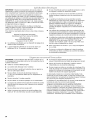
TABLEOF CONTENTS
VENT SYSTEM SAFETY ................................................................. 3
INSTALLATION REQUIREMENTS ................................................ 5
Tools and Parts ............................................................................ 5
Location Requirements ................................................................ 5
Electrical Requirements ............................................................... 7
Venting Requirements .................................................................. 7
INSTALLATION INSTRUCTIONS
INTERIOR-MOUNTED VENT MOTOR .......................................... 8
Venting Methods - Interior Mounted Vent Motor Only ................ 8
Install Vent System ....................................................................... 9
Rear Mounting - Blower Motor .................................................. 13
Complete Installation ................................................................. 15
Make Electrical Connections ..................................................... 15
Check Operation ........................................................................ 16
VENT SYSTEM USE ..................................................................... 17
Operating Downdraft Vent ......................................................... 17
VENT SYSTEM CARE .................................................................. 17
Surface of Downdraft Vent ......................................................... 17
Filters .......................................................................................... 17
WIRING DIAGRAM ....................................................................... 18
ASSISTANCE OR SERVICE ......................................................... 19
WAR RANTY .................................................................................. 20
TABLEDESMATIERES
SECURITE DU SYSTEME DE VENTILATION ............................ 22
EXIGENCES D'INSTALLATION ................................................... 24
Outillage et pieces ...................................................................... 24
Exigences d'emplacement ......................................................... 24
Specifications electriques .......................................................... 26
Exigences concernant I'evacuation ........................................... 26
INSTRUCTIONS D'INSTALLATION
VENTILATEUR MONTI_ .&L'INTI_RIEUR .................................... 27
M6thodes d'extraction - Seulement pour un
ventilateur monte a I'interieur ..................................................... 27
Installation du systeme d'extraction .......................................... 28
Montage du ventilateur & I'arriere .............................................. 32
Achever I'installation .................................................................. 34
Raccordements electriques ....................................................... 34
Contr61e du fonctionnement ...................................................... 35
UTILISATION DU SYSTEME D'EXTRACTION ........................... 36
Utilisation du systeme d'extraction ............................................ 36
ENTRETIEN DU SYSTEME D'EXTRACTION ............................. 36
Surface du systeme d'extraction ............................................... 36
Filtres .......................................................................................... 36
SCHI_MA DE C.&,BLAGE............................................................... 37
ASSISTANCE OU SERVICE ......................................................... 38
GARANTIE ..................................................................................... 39
2

VENTSYSTEMSAFETY
Your safety and the safety of others are very important.
We have provided many important safety messages in this manual and on your appliance. Always read and obey all safety
messages.
This is the safety alert symbol.
This symbol alerts you to potential hazards that can kill or hurt you and others.
All safety messages will follow the safety alert symbol and either the word "DANGER" or "WARNING."
These words mean:
You can be killed or seriously injured if you don't immediately
follow instructions.
You can be killed or seriously injured if you don't follow
instructions.
All safety messages will tell you what the potential hazard is, tell you how to reduce the chance of injury, and tell you what can
happen if the instructions are not followed.

iMPORTANT SAFETY iNSTRUCTiONS
WARNING: TO REDUCE THE RISK OF FIRE, ELECTRIC
SHOCK, OR INJURY TO PERSONS, OBSERVE THE
FOLLOWING:
m Use this unit only in the manner intended by the
manufacturer. If you have questions, contact the
manufacturer.
m Before servicing or cleaning the unit, switch power off at
service panel and lock the service disconnecting means to
prevent power from being switched on accidentally. When
the service disconnecting means cannot be locked,
securely fasten a prominent warning device, such as a tag,
to the service panel.
m Installation work and electrical wiring must be done by
qualified person(s) in accordance with all applicable codes
and standards, including fire-rated construction.
m Sufficient air is needed for proper combustion and
exhausting of gases through the flue (chimney) of fuel
burning equipment to prevent backdrafting. Follow the
heating equipment manufacturer's guideline and safety
standards such as those published by the National Fire
Protection Association (NFPA), the American Society for
Heating, Refrigeration and Air Conditioning Engineers
(ASHRAE), and the local code authorities.
m When cutting or drilling into wall or ceiling; do not damage
electrical wiring and other utilities.
m Ducted fans must always be vented outdoors.
CAUTION: For general ventilating use only. Do not use
to exhaust hazardous or explosive materials and vapors.
CAUTION: To reduce risk of fire and to properly exhaust
air, be sure to duct air outside - do not vent exhaust air into
spaces within walls or ceilings, attics or into crawl spaces,
or garages.
WARNING: TO REDUCE THE RISK OF FIRE, USE ONLY
METAL DUCTWORK.
WARNING: TO REDUCE THE RISK OF A RANGE TOP
GREASE FIRE:
m Never leave surface units unattended at high settings.
Boilovers cause smoking and greasy spillovers that may
ignite. Heat oils slowly on low or medium settings.
m Always turn hood ON when cooking at high heat or when
flambeing food (i.e. Crepes Suzette, Cherries Jubilee,
Peppercorn Beef Flamb6).
m Clean ventilating fans frequently. Grease should not be
allowed to accumulate on fan or filter.
m Use proper pan size. Always use cookware appropriate for
the size of the surface element.
WARNING: TO REDUCE THE RISK OF INJURY TO
PERSONS IN THE EVENT OF A RANGE TOP GREASE
FIRE, OBSERVE THE FOLLOWING: a
m SMOTHER FLAMES with a close fitting lid, cookie sheet, or
metal tray, then turn off the burner. BE CAREFUL TO
PREVENT BURNS. Ifthe flames do not go out
immediately, EVACUATE AND CALL THE FIRE
DEPARTMENT.
m NEVER PICK UP A FLAMING PAN - you may be burned.
m DO NOT USE WATER, including wet dishcloths or towels -
a violent steam explosion will result.
m Use an extinguisher ONLY if:
- You know you have a class ABC extinguisher, and you
already know how to operate it.
- The fire is small and contained in the area where it
started.
- The fire department is being called.
- You can fight the fire with your back to an exit.
aBased on "Kitchen Fire Safety Tips" published by NFPA.
SAVE THESE iNSTRUCTiONS

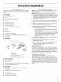
INSTALLATIONREQUIREMENTS
Gather the required tools and parts before starting installation.
Read and follow the instructions provided with any tools listed
here.
Tools Needed
• Jigsaw or keyhole saw
• Drill
• 1/8"(3 mm) drill bit for pilot holes
• Pencil
• Tape measure or ruler
• Flat-blade screwdriver
• Phillips screwdriver
• 3/8"(9.5 mm) nut driver or ratchet
• Level
• Pliers
• Metal snips
• Wire stripper or utility knife
• Caulking gun and weatherproof caulking compound
• Vent clamps
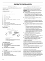
Parts Supplied
B
C E
A. Top trim (1)
B.End caps (2)
C. Overcounter support brackets (2)
D. Lower support legs (2)
E. Undercounter mounting brackets (2)
Other Parts Supplied
• Bag of fasteners (1)
• Metal cover (1)
• Optional support and 2 screws (36" [91.4 cm] models only)
• 6" diameter backdraft damper
Parts Needed
• Two UL listed or CSA approved 1/2"(12.7 mm) conduit
connectors.
• Wall cap for interior-mounted motor (1)
• Vent system
• Home power supply cable
• UL listed wire connectors (4)
NOTE: Downdraft vent is installed directly behind the cooktop.
Install the downdraft vent first, then install the cooktop.
IMPORTANT: Observe all governing codes and ordinances.
• Have a qualified technician install the downdraft vent. It is the
installer's responsibility to comply with installation clearances
specified on the model/serial rating plate. The model/serial
rating plate is located on the front of the downdraft vent
above the terminal box cover.
Downdraft vent location should be away from strong draft
areas, such as windows, doors, and strong heating vents or
fans.
Cabinet opening dimensions that are shown must be used.
Given dimensions provide minimum clearance.
Consult the cooktop manufacturer installation instructions
before making any cutouts.
Check that the downdraft vent and cooktop location will
clear the cabinet walls, backsplash, and rear wall studs
inside the cabinet.
Check for the minimum distance between the front edge
of the countertop and the front edge of the cooktop. The
minimum horizontal distance between the overhead
cabinets is the same as the width of the installed
downdraft vent.
All openings in ceiling and wall where the downdraft vent will
be installed must be sealed.
Grounded electrical outlet is required. See "Electrical
Requirements" section.
When installing the downdraft vent, the cabinet drawer will
need to be removed and the drawer front installed
permanently to the cabinet.
Cabinet Construction:
Downdraft vent is designed for use in a cabinet with a depth of
24" (61 cm). Some installations require a countertop deeper than
25" (63.5 cm). See the Countertop Cutout Dimensions section.
The maximum depth of the overhead cabinet is 13" (33 cm).
Overhead cabinets installed at either side of the downdraft vent
must be 18" (45.7 cm) above the cooking surface.
For Mobile Home Installations
The installation of this range hood must conform to the
Manufactured Home Construction Safety Standards, Title 24
CFR, Part 328 (formerly the Federal Standard for Mobile Home
Construction and Safety, title 24, HUD, Part 280) or when such
standard is not applicable, the standard for Manufactured Home
Installation 1982 (Manufactured Home Sites, Communities and
Setups) ANSI A225.1/NFPA 501A*, or latest edition, or with local
codes.

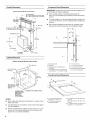
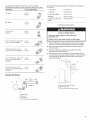
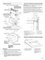
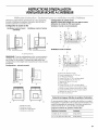
Product Dimensions
Interior=mounted blower motor model
Top trim widths:
_30V4" (76.8 cm) for 30" (76.2 cm) vent
36V4 (92.1 cm) for 36 (91.4 cm) vent
13W' (34.3 cm)
retractable
vent height
27" (68.6 cm) for 39" (76.2 cm) vent
33" (83.8 cm) for 36" (91.4
11/2" (3.8 cm)
(0.95 cm)
Terminam box cover
13" (33.0cm)
13" (33.0cm)
f
6" diameter
vent collar
(23.5 cm)
283/4,,
(73.0 cm)
Cabinet Dimensions
Interior-mounted blower motor model
_" (19.4 cm)
A= 1/2"(12.7 ram)
minimum
21%o"
(54.1 cm)
All cutouts are
for 6" (15.2 cm)
diameter vent
system.
Locate power
suppw Junction
pox a_lower
left hand
rear corner
of the cabinet.
Centerline of cooktop cutout
NOTES:
• See cooktop manufacturer's instructions for cooktop cutout
depth and width.
• Use dimensions for vent system cutout location that applies
to your installation.
• Interior mounted blower systems connect with 6" (15.2 cm)
round vent. The cutout locations for this vent system will
depend on your specific installation.
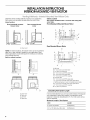
Countertop Cutout Dimensions
IMPORTANT: Countertops with a bull-nosed front edge are not
recommended for these installations.
• Some models require a countertop deeper than 25"
(63.5 cm); see the following Countertop Cutout Dimensions
section.
• To avoid mistakes, it is recommended that the cooktop and
vent cutouts be drawn on the countertop before making any
cutouts.
• See Cooktop Installation Instructions for complete cutout
dimensions, location dimensions and installation details.
-_-- D --_
B.... --,,L_c ----_,- --G
A. Downdraft vent
B. Cooktop
C. Measurement of eooktop rear
overhang.
D. D = Measurement of eooktop rear
overhang (C) + 11_,, [46.2 mm] (E)
A
!
E. 11_" (46.2 mm)
F. 7/2"(12.7 mm) minimum
G.¼" (6.4 mm)minimum
H.Countertop and backsplash
I. 7/2"(12.7mm) minimum
Countertop Cutout Dimensions
B
A. 7/2"(12. 7 mm) minimum to
backsplash or rear wall
B. ¾" (19.1 mm) maximum
backsplash depth
C. 27½" (69.9 cm) on 30" (76.2 cm)
models
33_" (85.9 cm) on 36" (91.4 cm)
models
D. D = Measurement of cooktop rear
overhang + 11_,, (46.2 mm)
6

IMPORTANT: Observe all governing codes and ordinances. Save
Installation Instructions for electrical inspector's use.
It is the customer's responsibility to contact a qualified electrical
installer, and to ensure that the electrical installation is adequate
and in conformance with National Electrical Code, ANSI/NFPA 70
(latest edition), or CSA Standards C22.1-94, Canadian Electrical
Code, Part 1 and C22.2 No. 0-M91 (latest edition) and all local
codes and ordinances.
If codes permit and a separate ground wire is used, it is
recommended that a qualified electrician determine that the
ground path is adequate.
A copy of the above code standards can be obtained from:
National Fire Protection Association
One Batterymarch Park, Quincy, MA 02269
CSA International
8501 East Pleasant Valley Road
Cleveland, OH 44131-5575
• This fan is suitable for use with solid state speed controls.
• The downdraft vent must be connected with copper wire
only.
• The downdraft vent should be connected directly to the
circuit breaker (or fused disconnect) box through flexible
armored or nonmetallic sheathed copper cable. Allow some
slack in the cable so the downdraft vent can be moved if
servicing is ever necessary.
• Wire sizes (copper wire only) and connections must conform
with the rating of the appliance as specified on the model/
serial rating plate located on the front of the downdraft vent
above the wiring box cover.
• Wire sizes must conform to the requirements of the National
Electrical Code, ANSI/NFPA 70 (latest edition), or CSA
Standards C22.1-94, Canadian Electrical Code, Part 1 and
C22.2 No. 0-M91 (latest edition) and all local codes and
ordinances.
Two UL listed or CSA approved 1/2"(12.7 mm) conduit
connectors.
• A 120 Volt, 60 Hz., AC only 15-amp fused, electrical circuit is
required.
• Check with a qualified electrician if you are not sure the
downdraft vent is properly grounded.
• A wiring diagram is located on the downdraft vent base
above the power control board cover.
IMPORTANT: Make sure there is proper clearance within the wall
or floor before making exhaust vent cutouts.
• Use heavy (rigid) metal vent.
• Venting system must terminate to the outside.
• Do not terminate the vent system in an attic or other enclosed
area.
• Do not use 4" (10.2 cm) laundry-type wall caps.
• Do not install 2 elbows together.
• Do not use plastic or metal foil vent.
• The length of vent system and number of elbows should be
kept to a minimum to provide efficient performance.
• Use no more than three 90° elbows
• Make sure there is a minimum of 24" (61 cm) of straight vent
between the elbows if more than one elbow is used.
• Use clamps to seal all joints in the vent system.
• Use caulking tape to seal the exterior wall or floor opening
around cap.
• Do not cut joist or stud. If vent cutout falls over a joist or stud,
a supporting frame must be constructed.
Flexible metal vent is not recommended. If it is used, calculate
each foot of flexible vent as 2 ft (0.6 m) of rigid metal vent.
Flexible elbows count twice as much as standard elbows.
Recommended vent system length:
For either interior-mounted or exterior-mounted blower
installations, the vent system length should not exceed the
maximum lengths listed in the Maximum Length of Vent System
chart. See "Calculating Vent System Length" in the "Venting
Methods - Interior Mounted Vent Motor Only" section.

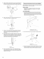
INSTALLATIONINSTRUCTIONS
INTERIOR-MOUNTEDVENTMOTOR
Determine which venting method is best for your application.
Vent system can terminate through either the wall or floor.
Island location
Front (standard)mounted
blower motor
Rear mounted blower
motor
q
.............................................................A
J
A. Down vent
NOTE: For island locations, the blower motor can be mounted for
right, left, or rear venting if needed for your application. Most
island applications would still require the venting to be directed
down through the floor.
Built-in cabinet locations
Island Location
Vent system installedunder a concrete slab using PVC
sewer pipe.
Front (Standard) Mounted Blower Motor
i! i!
K
B
J
:___oo_,_............ _o :,_ .........H
J
Rear Mounted Blower Motor
B
S
C
A
!
I
A. Down vent
B. Rear vent
C. Left vent
D. Right vent
I II ..........D
A. Wall cap
B. 6" (15.2 cm) round metal vent
C. 16" (40.6 cm) maximum
D. 6" (15.2 cm) round PVC sewer pipe
E. 6" (15.2 cm) round metal vent
F. 6" (15.2 cm) round PVC coupling
G. Concrete slab
H. 6" (15.2 cm) round PVC sewer pipe
I. 6" (15.2 cm) round 90 ° PVC sewer pipe elbow
J. Tightly pack gravel or sand completely around pipe.
K. 6" (15.2 cm) round 90 ° PVC sewer pipe elbow
L. 6" (15.2 cm) round PVC coupling
M. 12" (30.5 cm) minimum
Calculating Vent System Length
It is recommended that you use round vent instead of rectangular
vent, especially if elbows are required. If rectangular vent is
required, it should be transitioned to 6" (15.2 cm) round vent as
soon as possible.
Maximum Length of Vent System
Vent Length
6" (15.2 cm) round 35 ft (8.9 m)
3V4" x 10" (8.3 cm x 25.4 cm) 35 ft (8.9 m)
8

To calculate the length of the system you need, add the
equivalent feet (meters) for each vent piece used in the system.
Vent Piece 6" (15.2 cm) Round
45° elbow 2.5 ft
(0.8m)
90° elbow 5.0 ft
(1.5m)
6" (15.2 cm) 0.0 ft
wall cap (0.0 m)
31/4"x 10" (8.3 cm x 25.4 cm) 4.5 ft
to 6" (15.2 cm) transition (1.4 m)
6" (15.2 cm) to 31/4'' x 10" 1 ft
(8.3 cm x 25.4 cm) transition (0.3 m)
31/4"x 10" (8.3 cm x 25.4 cm) 5.0 ft
to 6" (15.2 cm) 90° elbow (1.5 m)
transition
6" (15.2 cm) to 31/4'' x 10" 5.0 ft
(8.3 cm x 25.4 cm) 90° elbow (1.5 m)
transition
Example Vent System
C
2 ft (0.6 rn)
The following example falls within the maximum vent length of
35 ft (8.9 m).
2 - 90° elbow
1 - wall cap
8 ft (2.4 m) straight
Transition
Length of 6" (15.2 cm)
system
= 10.0 ft (3 m)
= 0.0 ft (0.0 m)
= 8.0 ft (2.4 m)
= 4.5 ft (1.4 cm)
= 22.5 ft (6.8 m)
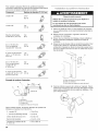
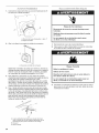
Excessive Weight Hazard
Use two or more people to move and install
downdraft vent.
Failure to do so can result in back or other injury.
1.
2.
3.
4.
Place cardboard or similar material on top of a flat surface
where you can easily assemble the downdraft vent system.
Remove parts packages, downdraft vent and blower box
from the carton.
Remove all shipping materials, tape and film from the
downdraft vent and blower box.
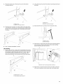
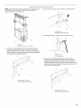
Remove screws from each side of the vent. Attach the left
and right side overcounter support brackets to the downdraft
vent and push up to align the screw holes. Use screws to
secure the brackets.
A. Overcounter support bracket
B. Blower motor box
C. Overcounter support bracket screw
D
A. Blower motor
B. Transition
C. 90 ° elbows
D. 6" backdraft damper (suppfied)

5=
6=
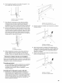
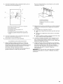
Attach the left and right side end caps to the downdraft vent.
Place the end cap upon the overcounter support, slide the
tab into the slot and snap into place over the the plastic tabs.
A
A. Blower motor box
B. Support leg
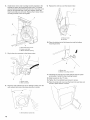
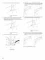
7. Using 2 or more people, insert the downdraft vent into the
countertop cutout. Check that downdraft vent is parallel to
side of cutout and that mounting brackets overlap
countertop.
8. Move support legs down against cabinet floor. Place a level
against the front of the downdraft vent base and adjust until
downdraft vent is level vertically. Use a pencil to mark the top
of each leg on the downdraft vent and the location of the
support leg mounting holes on the cabinet floor.
9=
A
A. Level
B. Mark locations.
Remove downdraft vent from cutout. Drill starter holes at
each mounting screw location on the cabinet floor. Align top
of legs with pencil marks on the face of the downdraft vent.
Tighten screws in legs.
Determine which direction is best for your installation.
When installed in a cabinet, vent system can exhaust through the
bottom, right, left or rear of the cabinet.
Bottom venting:
Downdraft vent is shipped with blower in down venting
position so no modification is required. See "Complete
Installation" section.
Left or right venting:
1. Loosen the 2 hex/slotted head screws that attach the top
bracket that secures the motor to the vent box enough to
slide the bracket into the "Z" slots. This will move the bracket
away from the top mounting lip of the blower box and allow it
to tilt away from the vent box panel.
A
....g
2=
@
A.Bracket with "Z" slots
B.Hex/slotted head screws (2)
Lift up the blower box from the bottom mounting channel.
3=
A. Blower box
A
B. Bottom mounting channel
Rotate it 90 degrees to the left or right so that the vent blower
damper is repositioned in the direction needed. Do not twist
or bind the wires or disconnect the wiring from the blower.
10

4. Place the bottom tab of the blower box into the bottom 2. Lift up the blower box from the bottom mounting channel and
mounting channel, set aside.
@
5=
A. Blower box
B. Bottom mounting channel
Tilt blower box top tab so it is flush with the vent box panel
and position it under the top mounting bracket. Slide bracket
into the "Z" slots and tighten the 2 hex/slotted head screws
to secure.
See "Complete Installation" section.
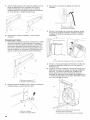
Rear Venting:
1. Remove the vent box. Loosen the 2 hex/slotted head screws
that attach the top bracket that secures the motor to the vent
box enough to slide the bracket into the "Z" slots. This will
move the bracket away from the top mounting lip of the
blower box and allow it to tilt away from the vent box panel.
A
A. Bracket with "Z" slots
B. Hex/slo tted head screws (2)
3=
@
B
A
A.Blower box
B.Bottom mounting channel
Disconnect the wire connector from the blower motor.
\
\
\
\
B
A. Blower motor
B. Wire connector
4. Remove the 2 screws that mount the motor mounting bracket
to the vent box. Remove the blower motor and mounting
bracket assembly from the vent box.
........A
A. Blower motor mounting bracket screws (2)
5. Remove the 4 screws from the small cover plate on the rear
of the vent chamber and set screws and cover plate aside.
11

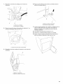
6.
7.
8.
Install blower motor and mounting bracket assembly to the
bracket just below the downdraft tower motor. The blower
exhaust opening should fit through the hole in the large cover
plate on the opposite side of the vent chamber where the
small cover plate was removed. Replace the 2 blower motor
mounting bracket screws and tighten.
C
A.Downdraft tower motor
B.Large coverplate
C.Blower exhaust opening
Plug in the wire connector to the blower motor.
1
s_
A
B
A. Blower motor
B. Wire connector
Place the vent extension for the 6" diameter venting over the
vent exhaust and screw into place using the 4 screws.
9. Replace the vent box over the blower motor.
B
//'
A.Blower motor
B. Ventbox
10. Place the bottom tab of the blower box into the bottom
mounting channel.
/
A
A. Blower box
B. Bottom mounting channel
11. Tilt blower box top tab so it is flush with the vent box panel
and position it under the top mounting bracket.
12. Slide bracket into the "Z" slots.
13. Tighten the 2 hex/slotted head screws to secure.
14. Place the small vent cover over the hole in the vent box and
secure in place with the 4 screws.
/
A
A. Vent extension screws (4)
12

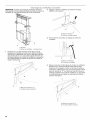
NOTE: Optional blower motor mounting position (opposite side).
The blower motor box assembly can also be moved to the
opposite side (rear) of the vent box.
_s_ _I_,_ _"_,_"_u,s_,,,Bowe_ _I_@oo
2. Lift up the blower box from the bottom mounting channel.
@
B
A
1=
A
A. Panel
B. Blower motor - rear mounting
Loosen the 2 hex/slotted head screws that attach the top
bracket that secures the motor to the vent box enough to
slide the bracket into the "Z" slots. This will move the bracket
away from the top mounting lip of the blower box and allow it
to tilt away from the vent box panel.
A
3.
4=
A. Blower box
B. Bottom mounting channel
Disconnect the wire connector from the blower motor.
o
B
A. Blower motor
B. Wire connector
Remove panel from the opposite side of blower motor.
Loosen the 2 hex/slotted head screws that attach the top
bracket that secures the panel to the vent box enough to
slide the bracket into the "Z" slots. This will move the bracket
away from the top mounting lip of the panel and allow it to tilt
away from the vent box panel.
@
A. Bracket with "Z" slots
B. Hex/slo tted head screws (2)
A
A. Bracket with "Z" slots
B. Hex/slotted head screws (2)
13

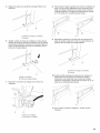
5. Lift up the panel from the bottom mounting channel.
6,
@
B
A
A. Blower mounting channel
B. Panel
Install the blower motor box assembly to the opposite side
(rear) of the vent box with the vent located in the bottom
venting position. Place the bottom tab of the blower box into
the bottom mounting channel.
@
A
B
A. Blower mounting channel
B. Panel
7. Plug in the wire connector to the blower motor.
A. Blower motor
B. Wire connector
8,
Tilt blower box top tab so it is flush with the vent box panel
and position it under the top mounting bracket. Slide bracket
into the "Z" slots and tighten the 2 hex/slotted head screws
to secure.
Reinstall panel to front side of vent box panel. Place bottom
tab of the panel into the bottom mounting channel.
@
B
A. Blower mounting channel
B. Panel
10. Tilt panel top tab so it is flush with the vent box panel and
position it under the tip mounting bracket. Slide bracket into
the "Z" slots and tighten the 2 hex/slotted head screws to
secure.
@
11. See "Complete Installation" section.
14

1=
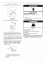
Attach backdraft damper over 6" vent extension. Secure with
vent clamp.
"_ _ _ E •.... __ _ E_ ,,_,_ / =W_,
Electrical Shock Hazard
Disconnect power before servicing.
Replace all parts and panels before operating.
Failure to do so can result in death or electrical shock.
A. 6" vent extension
B. Backdraft damper
2. Remove screw attaching the terminal box cover.
3=
4=
A
A. Terminal box cover
Determine which direction (rear or bottom) electrical
connection will need to run from vent system terminal box.
Remove rear or bottom knockout and install a UL listed or
CSA approved conduit connector.
Using 2 or more people, insert the downdraft vent into the
countertop cutout. Position downdraft vent so it is centered
in cutout and parallel to edge of cutout. Check that downdraft
vent is level vertically. Then fasten lower support legs to the
cabinet floor with screws.
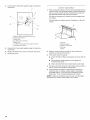
Attach 1 undercounter bracket on front upper right corner of
downdraft vent with slot over vent mounting hole and flange
against countertop. Attach other bracket to left side of the
downdraft vent. Drill starter holes through undercounter
mounting brackets into the underside of the countertop.
Insert appropriate length screws into holes and tighten
brackets to countertop.
B_ C
,P
f'
A. When attaching undercounter bracket to underside
of countertop, make sure that the screw length will
not go through countertop when tightened.
B. Backsplash
C. Countertop
1. Disconnect power.
2. Feed the power supply cable through the conduit connector
and into the terminal box.
Fire Hazard
Electrically ground the blower.
Use copper wire.
Connect ground wire to green ground screw in
terminal box.
Failure to do so can result in death, fire, or
electrical shock.
3. Attach the green (or green and yellow) ground wire to the
green ground screw. Tighten the conduit connector clamp
screws.
15

4,
Connect the 2 white wires together using UL listed wire
connectors.
F
J
C
E
1,
Push and hold the button on the top of the downdraft vent for
a few seconds. The retractable section of the downdraft vent
will rise, and the blower will start. Position the top trim over
the retractable section and snap trim into place.
Trim kits for matching your cooktop color are available from
your dealer.
For information on ordering, see the "Assistance or Service"
section.
B
A. Green or green and yellow ground wire
B. Green ground screw
C. White wires
D. UL listed wire connectors
E.Black wires
F. UL listed or CSA approved conduit connector
G. Downdraft vent wiring
5. Connect the 2 black wires together using UL listed wire
connectors.
6. Replace the terminal box cover and secure with screw.
7. Reconnect power.
E
A. Top trim
B. ON/OFF button
C. Blower control slider
D. End cap
E.Filters
2,
3.
Slide the control slider on the side of vent to check the
operation and speed of the blower.
If the blower does not operate:
• Check that filter or filters are pressed in as far as they will
go.
• Check that the circuit breaker has not tripped or a
household fuse blown.
• Check downdraft vent fuse located under power board.
4. Connect vent system to blower. Vent system must end with a
wall or roof cap. Use clamps to seal all joints.
5. Install cooktop according to manufacturer's instructions.
Check that rear of cooktop overlaps edge of retractable
downdraft vent by 3/8"(9.5 mm). See "Countertop Cutout
Dimensions" in the "Location Requirements" section.
NOTE: To get the most efficient use from your new retractable
downdraft vent, read the "Vent System Use" section.
16

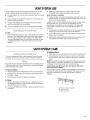
VENTSYSTEMUSE
The retractable downdraft vent system is designed to remove
smoke, cooking vapors and odors from the cooktop area.
• For best results, the vent should be operating before cooking
is started.
• If you use large or tall utensils, place them on the large rear
element or burner surface.
• A higher heat setting than normally used may be needed
when the downdraft vent is operating.
• This fan is suitable for use with solid-state speed controls.
To Use:
1. Push and hold the button on top of downdraft vent for a few
seconds. (This slight delay helps avoid inadvertent raising of
the vent during cleaning of the cooktop area.) Retractable
section of downdraft vent will rise. Blower will begin to vent
immediately if blower control knob slider is set to an "On"
position.
2. Slide the control slider on the right-hand side of the
downdraft vent to adjust the blower motor speed.
When cooking is complete:
1. Push the button on top of the retractable downdraft vent. The
blower will turn off, and the retractable section of the vent will
return to the closed position.
If a spill occurs on the cooktop that allows liquids to seep inside
the downdraft vent, you must turn the downdraft vent off
immediately. It is possible to cause damage to the downdraft
vent if water is allowed inside the downdraft vent while it is
operating.
1. Immediately turn off the downdraft vent at the speed control
located on the right-hand side of the downdraft vent.
2. Turn off the power supply to the downdraft vent at the circuit
breaker box or fuse box.
3. Allow plenty of time for the downdraft vent to dry naturally. Do
not open the downdraft vent to remove the water.
VENTSYSTEMCARE
To avoid damaging the finish, clean downdraft vent with soap
and water. Do not use scouring powder or abrasive solutions.
Frequently remove and clean the filter(s) in the retractable section
of the downdraft vent. This will improve the operating efficiency
of the downdraft vent system.
To Remove Filters:
1. Place fingertips in the embossment at the top for the filters.
2. Press down on the filters far enough for the tab at the top of
the filters to clear.
3. Pull forward to release the filter from its groove.
To Replace Filters:
1. Place filters into the retractable section of the downdraft vent.
2. Place fingertips into the embossment at the top of the filters
and push down and back to allow the top tabs to snap into
place.
NOTE: Downdraft vent will not operate if the filters are not in their
proper position. If the filters' top tabs are not locked behind the
top flange, the vent may retract but not raise back up.
If retractable downdraft vent does not operate after clean
filters have been installed:
Push the filter in as far as it will go. When the filter is removed, the
microswitch behind the filter is inactivated. This feature will not
allow the vent system to operate until the filter is properly
installed.
A
To Clean:
1. Remove the filter(s) and clean them in a dishwasher or in a
hot detergent solution. The downdraft vent will not operate
when the filters are not in place.
2. Dry the clean filter(s) and reinstall, making sure that they lock
into place.
A. Filter removal embossment
B. Left metal filter
C. Right metal filter
17

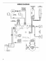
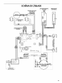
WIRING DIAGRAM
O
BLK
LiNE iN 120
Vac 60 Nz
5x20 800 mA
Time Delay
_RED _ RED
×iii__1:_ "-' _}1_=BLKI)--IaxBLK
O d _ ( FILTER _ O
"L__ I kSWITCHESJ
I t GRY
I, GRY
I TOROIDAL 1
TRANSFORMER
BLK
BLU
BRW
CN8
_RL1
CN2
PUSH BUTTON q _ SPEED
UPIDOWN J [REGULATIONJ
FLAT CABLE
0
HH
ORG
GRY
WHT
II
d
z
z
d
z
18

ASSISTANCEOR SERVICE
When calling for assistance or service, please know the purchase
date and the complete model and serial number of your
appliance. This information will help us to better respond to your
request.
If you need replacement parts
If you need to order replacement parts, we recommend that you
use only factory specified parts. Factory specified parts will fit
right and work right because they are made with the same
precision used to build every new appliance. To locate factory
specified replacement parts in your area, call us or your nearest
designated service center.
n S A
If the problem is not due to one of the items listed in the
"Troubleshooting" section...
Call the dealer from whom your appliance was purchased, or call
Jenn-Air at 1-800-688-1100 to locate an authorized service
company. When calling, please know the purchase date and the
complete model and serial number of your appliance. Be sure to
retain proof of purchase to verify warranty status.
If the dealer or service company cannot resolve your problem,
write to:
Jenn-Air Brand Home Appliances
Customer eXperience Center
553 Benson Road
Benton Harbor, MI 49022-2692
Web address: www.jennair.com
Or call: 1-800-688-1100
U.S. customers using -I-I-Yfor deaf, hearing impaired or speech
impaired, call: 1-800-688-2080.
NOTE: When writing or calling about a service problem, please
include the following information:
1. Your name, address and daytime telephone number.
2. Appliance model number and serial number.
3. Name and address of your dealer or servicer.
4. A clear description of the problem you are having.
5. Proof of purchase (sales receipt).
User's guides, service manuals and parts information are
available from Jenn-Air Brand Home Appliances, Customer
eXperience Center.
If the problem is not due to one of the items listed in the
"Troubleshooting" section...
Call the dealer from whom your appliance was purchased, or call
Jenn-Air at 1-800-807-6777 to locate an authorized service
company. When calling, please know the purchase date and the
complete model and serial number of your appliance. Be sure to
retain proof of purchase to verify warranty status.
If the dealer or service company cannot resolve your problem,
write to:
Jenn-Air Brand Home Appliances
Customer eXperience Centre
1901 Minnesota Court
Mississauga, ON LSN 3A7
Web address: www.jennair.ca
Or call: 1-800-807-6777.
NOTE: When writing or calling about a service problem, please
include the following information:
1. Your name, address and daytime telephone number.
2. Appliance model number and serial number.
3. Name and address of your dealer or servicer.
4. A clear description of the problem you are having.
5. Proof of purchase (sales receipt).
User's guides, service manuals and parts information are
available from Jenn-Air Brand Home Appliances, Customer
eXperience Centre.
NOTE: Instructions are included with each kit.
For model series JXDR7301V
30" (76.2 cm) one-piece trim:
Part Number W10187288 (black)
For model series JXDR7361V
36" (91.4 cm) one-piece trim:
Part Number W10187290 (black)
19

JENN-AIR MAJOR APPLIANCEWARRANTY
ONE YEAR LIMITED WARRANTY
For one year from the date of purchase, when this major appliance is operated and maintained according to instructions attached to or
furnished with the product, Jenn-Air brand of Whirlpool Corporation or Whirlpool Canada LP (hereafter "Jenn-Air") will pay for factory
specified parts and repair labor to correct defects in materials or workmanship. Service must be provided by a Jenn-Air designated
service company. This limited warranty is valid only inthe United States or Canada and applies only when the major appliance is used
in the country in which it was purchased. Outside the 50 United States and Canada, this limited warranty does not apply. Proof of
original purchase date is required to obtain service under this limited warranty.
ITEMS EXCLUDED FROM WARRANTY
This limited warranty does not cover:
1. Service calls to correct the installation of your major appliance, to instruct you on how to use your major appliance, to replace or
repair house fuses, or to correct house wiring or plumbing.
2. Service calls to repair or replace appliance light bulbs, air filters or water filters. Consumable parts are excluded from warranty
coverage.
3. Repairs when your major appliance is used for other than normal, single-family household use or when it is used in a manner that is
contrary to published user or operator instructions and/or installation instructions.
4. Damage resulting from accident, alteration, misuse, abuse, fire, flood, acts of God, improper installation, installation not in
accordance with electrical or plumbing codes, or use of consumables or cleaning products not approved by Jenn-Air.
5. Cosmetic damage, including scratches, dents, chips or other damage to the finish of your major appliance, unless such damage
results from defects in materials or workmanship and is reported to Jenn-Air within 30 days from the date of purchase.
6. Any food loss due to refrigerator or freezer product failures.
7. Costs associated with the removal from your home of your major appliance for repairs. This major appliance is designed to be
repaired in the home and only in-home service is covered by this warranty.
8. Repairs to parts or systems resulting from unauthorized modifications made to the appliance.
9. Expenses for travel and transportation for product service if your major appliance is located in a remote area where service by an
authorized Jenn-Air servicer is not available.
10. The removal and reinstallation of your major appliance if it is installed in an inaccessible location or is not installed in accordance
with published installation instructions.
11. Major appliances with original model/serial numbers that have been removed, altered or cannot be easily determined. This warranty
is void if the factory applied serial number has been altered or removed from your major appliance.
The cost of repair or replacement under these excluded circumstances shall be borne by the customer.
DISCLAIMER OF IMPLIED WARRANTIES; LIMITATION OF REMEDIES
CUSTOMER'S SOLE AND EXCLUSIVE REMEDY UNDER THIS LIMITED WARRANTY SHALL BE PRODUCT REPAIR AS PROVIDED
HEREIN. IMPLIED WARRANTIES, INCLUDING WARRANTIES OF MERCHANTABILITY OR FITNESS FOR A PARTICULAR PURPOSE,
ARE LIMITED TO ONE YEAR OR THE SHORTEST PERIOD ALLOWED BY LAW. JENN-AIR SHALL NOT BE LIABLE FOR INCIDENTAL
OR CONSEQUENTIAL DAMAGES. SOME STATES AND PROVINCES DO NOT ALLOW THE EXCLUSION OR LIMITATION OF
INCIDENTAL OR CONSEQUENTIAL DAMAGES, OR LIMITATIONS ON THE DURATION OF IMPLIED WARRANTIES OF
MERCHANTABILITY OR FITNESS, SO THESE EXCLUSIONS OR LIMITATIONS MAY NOT APPLY TO YOU. THIS WARRANTY GIVES
YOU SPECIFIC LEGAL RIGHTS, AND YOU MAY ALSO HAVE OTHER RIGHTS WHICH VARY FROM STATE TO STATE OR PROVINCE
TO PROVINCE.
If outside the 50 United States and Canada, contact your authorized Jenn-Air dealer to determine if another warranty applies.
If you need service, first see the "Troubleshooting" section of the Use & Care Guide. After checking "Troubleshooting," you may find
additional help by checking the "Assistance or Service" section or by calling Jenn-Air. In the U.S.A., call 1-800-688-1100. In Canada,
call 1-800-807-6777. 9/07
Keep this book and your sales slip together for future
reference. You must provide proof of purchase or installation
date for in-warranty service.
Write down the following information about your major appliance
to better help you obtain assistance or service if you ever need it.
You will need to know your complete model number and serial
number. You can find this information on the model and serial
number label located on the product.
Dealer name
Address
Phone number
Model number
Serial number
Purchase date
20
La page est en cours de chargement...
La page est en cours de chargement...
La page est en cours de chargement...
La page est en cours de chargement...
La page est en cours de chargement...
La page est en cours de chargement...
La page est en cours de chargement...
La page est en cours de chargement...
La page est en cours de chargement...
La page est en cours de chargement...
La page est en cours de chargement...
La page est en cours de chargement...
La page est en cours de chargement...
La page est en cours de chargement...
La page est en cours de chargement...
La page est en cours de chargement...
La page est en cours de chargement...
La page est en cours de chargement...
La page est en cours de chargement...
La page est en cours de chargement...
-
 1
1
-
 2
2
-
 3
3
-
 4
4
-
 5
5
-
 6
6
-
 7
7
-
 8
8
-
 9
9
-
 10
10
-
 11
11
-
 12
12
-
 13
13
-
 14
14
-
 15
15
-
 16
16
-
 17
17
-
 18
18
-
 19
19
-
 20
20
-
 21
21
-
 22
22
-
 23
23
-
 24
24
-
 25
25
-
 26
26
-
 27
27
-
 28
28
-
 29
29
-
 30
30
-
 31
31
-
 32
32
-
 33
33
-
 34
34
-
 35
35
-
 36
36
-
 37
37
-
 38
38
-
 39
39
-
 40
40


Jenn-Air JXDR7361VS1 Le manuel du propriétaire
- Taper
- Le manuel du propriétaire
- Ce manuel convient également à
dans d''autres langues
- English: Jenn-Air JXDR7361VS1 Owner's manual