Lifetime 290038 Le manuel du propriétaire
- Taper
- Le manuel du propriétaire

1
Keep this Product ID Number and use when contacting Customer Service:
MODEL N° 290038
OWNER’S MANUAL
COPY

2
INSTRUCTION #1052703 M
11/03/2015
REGISTER YOUR PRODUCT ONLINE AT WWW.LIFETIME.COM
LIFETIME’S PROMISE TO YOU:
We invite you to read our privacy policy at www.lifetime.com
REGISTER today!
At Lifetime
®
, we are committed to providing innovative and quality products. While registering, you will have the opportunity to give us your feedback. Your
input is valuable to us.
• You can also opt in to receive new product noti cations or promotions.
• In the unlikely event of a product recall or safety modi cation, your registration provides the information we need to notify you
directly.
• Registration is fast, easy, and completely voluntary.
Maintaining your privacy is our long-standing policy at Lifetime
®
. And you can rest assured that Lifetime
®
will not sell or provide
your personal data to other third parties, or allow them to use your personal data for their own purposes.
This product is intended for use by children ages 3 to 10,
and is for outdoor residential use only.
Most injuries are caused by misuse and/or not following instructions. Use caution when using this product.
To ensure safety, do not attempt to assemble this product without reading and following all instructions carefully. Check the entire
box and inside all packing materials for parts and/or additional instruction material. Before beginning assembly, identify and inventory
all parts and hardware using the parts and hardware lists and identi ers in this document. Proper and complete assembly, use and
supervision are essential for proper orientation and to reduce the risk of accident or injury. A high probability of serious injury exists
if this product is not installed, maintained, and/or operated properly. Failure to comply with any of the warnings in this instruction
manual may result in serious personal injuries such as cuts, broken bones, nerve damage, paralysis, brain injury, or death. Failure to
comply may also result in property damage. Please heed all warnings and cautions.
FAILURE TO FOLLOW THESE WARNINGS MAY RESULT IN SERIOUS INJURY OR PROPERTY
DAMAGE AND WILL VOID WARRANTY.
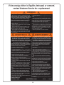
SAFETY INSTRUCTIONS
Save this owner’s manual for future reference and in the event that the manufacturer has to be contacted.
**U.S. and Canada customers ONLY**
FOR CUSTOMERS OUTSIDE THE U.S. OR CANADA, PLEASE CONTACT
THE STORE FOR ASSISTANCE.
DO NOT CONTACT THE STORE!
CALL OUR CUSTOMER SERVICE DEPARTMENT at
1 (800) 225-3865
HOURS: 7:00 a.m. to 5:00 p.m. Monday through Friday (MST)
9:00 a.m. to 1:00 p.m. Saturday (MST)
Questions or Missing Parts?
ID:
TO SAVE TIME WHEN CONTACTING CUSTOMER SERVICE, PLEASE HAVE THE PRODUCT ID AVAILABLE BEFORE YOU CALL; IT’S LOCATED AT THE BOTTOM-LEFT CORNER
OF THE FRONT PAGE OF THIS MANUAL.
This product is intended for use by children ages 3 to 12,
and is for outdoor residential use only.
COPY

3
BEFORE BEGINNING ASSEMBLY
Keep the hardware bags and their contents separate. If any parts are missing, call our
Customer Service Department.
Identify and inventory all parts and hardware using the parts and hardware lists and
identi ers in this document.
Test t all Bolts by inserting them into their respective holes. If necessary, carefully
scrape away any excess powder coating buildup from inside the holes. Do not scrape
away all of the powder coating. Bare metal may rust. You may need to pound some
Bolts into place with a hammer or mallet.
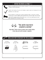
TOOLS AND PARTS REQUIRED FOR THIS ASSEMBLY
*Two adults required to
complete assembly*
Only adults should set up the product. Do not allow children
in the setup area until assembly is complete.
7/32” Allen Wrench 3/16” Allen Wrench
(included) (included)
9/16” Wrench
(2)
Screwdriver
(1)
(2)
REGISTER YOUR PRODUCT ONLINE AT WWW.LIFETIME.COM
LIFETIME’S PROMISE TO YOU:
We invite you to read our privacy policy at www.lifetime.com
REGISTER today!
At Lifetime
®
, we are committed to providing innovative and quality products. While registering, you will have the opportunity to give us your feedback. Your
input is valuable to us.
• You can also opt in to receive new product noti cations or promotions.
• In the unlikely event of a product recall or safety modi cation, your registration provides the information we need to notify you
directly.
• Registration is fast, easy, and completely voluntary.
Maintaining your privacy is our long-standing policy at Lifetime
®
. And you can rest assured that Lifetime
®
will not sell or provide
your personal data to other third parties, or allow them to use your personal data for their own purposes.
This product is intended for use by children ages 3 to 10,
and is for outdoor residential use only.
Most injuries are caused by misuse and/or not following instructions. Use caution when using this product.
To ensure safety, do not attempt to assemble this product without reading and following all instructions carefully. Check the entire
box and inside all packing materials for parts and/or additional instruction material. Before beginning assembly, identify and inventory
all parts and hardware using the parts and hardware lists and identi ers in this document. Proper and complete assembly, use and
supervision are essential for proper orientation and to reduce the risk of accident or injury. A high probability of serious injury exists
if this product is not installed, maintained, and/or operated properly. Failure to comply with any of the warnings in this instruction
manual may result in serious personal injuries such as cuts, broken bones, nerve damage, paralysis, brain injury, or death. Failure to
comply may also result in property damage. Please heed all warnings and cautions.
FAILURE TO FOLLOW THESE WARNINGS MAY RESULT IN SERIOUS INJURY OR PROPERTY
DAMAGE AND WILL VOID WARRANTY.
SAFETY INSTRUCTIONS
Save this owner’s manual for future reference and in the event that the manufacturer has to be contacted.
**U.S. and Canada customers ONLY**
FOR CUSTOMERS OUTSIDE THE U.S. OR CANADA, PLEASE CONTACT
THE STORE FOR ASSISTANCE.
DO NOT CONTACT THE STORE!
CALL OUR CUSTOMER SERVICE DEPARTMENT at
1 (800) 225-3865
HOURS: 7:00 a.m. to 5:00 p.m. Monday through Friday (MST)
9:00 a.m. to 1:00 p.m. Saturday (MST)
Questions or Missing Parts?
ID:
TO SAVE TIME WHEN CONTACTING CUSTOMER SERVICE, PLEASE HAVE THE PRODUCT ID AVAILABLE BEFORE YOU CALL; IT’S LOCATED AT THE BOTTOM-LEFT CORNER
OF THE FRONT PAGE OF THIS MANUAL.
Scrap Wood
(1)
5/8” Wrench
(1)
Adjustable Wrench
(1)
Ladder
(1)

4
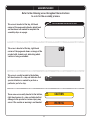
This area is located at the top, left-hand
corner of the page and indicates which tools
and hardware are needed to complete the
assembly steps on a page.
This area is located at the top, right-hand
corner of the page and shows an image of the
product with shaded parts indicating which
section is being assembled.
SEC
#
Note:
!
Refer to the following areas throughout the instructions
to assist in the assembly process:
This area is usually located in the bottom,
left-hand corner of a step and indicates that
special attention is needed to perform a
particular part of a step.
These areas are usually located in the bottom,
right-hand corner of a step and indicate that
damage to the product or serious injury may
occur if the caution or warning is not heeded.
WARNING
ASSEMBLY GUIDES
TOOLS AND HARDWARE REQUIRED FOR THIS PAGE
CAUTION

5
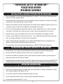
**IMPORTANT SAFETY INFORMATION**
PLEASE READ BEFORE
BEGINNING ASSEMBLY:
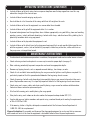
Installation and Ground Preparation Instructions:
• Placetheequipmentonalevel,well-drainedground,notlessthan6ft(1.8m)fromanystructureorobstruc-
tionsuchasafence,garage,orhouse.
• Provideenoughroomsothatchildrencanusetheequipmentsafely.Forexample,forstructureswithmultiple
playactivities,aslideshouldnotexitinfrontofaswing.
• Separateactiveandquietactivitiesfromeachother.Forexample,locatesandboxesawayfromswingsoruse
aguardrailorbarriertoseparatethesandboxfromthemovementoftheswings.
• Donotinstallhomeplaygroundequipmentoverconcrete,asphalt,packedearth,grass,carpet,oranyother
hardsurface.Afallontoahardsurfacecanresultinseriousinjurytotheequipmentuser(seepage7).
• Topreventseriousinjury,warnchildrenthattheymustnotusetheequipmentuntilproperlyinstalled.
• Createasitefreeofobstaclesthatcouldcauseinjuries–suchaslowoverhangingtreebranches,overhead
wires,treestumpsand/orroots,largerocks,bricks,andconcrete.
• Choosealevellocationfortheequipment.Thiscanreducethelikelihoodoftheplaysettippingoverand
loose-llsurfacingmaterialswashingawayduringheavyrains
• ForanyquestionscallourCustomerServiceDepartmentat1-800-225-3865formoreinformation.
Playground and Surface Materials Instructions:
• Usecontainment,suchasdiggingoutaroundtheperimeterand/orliningtheperimeterwithlandscapeedging.
• Donotinstallloosellsurfacingoverhardsurfacessuchasconcreteorasphalt.
• Installationsofrubbertilesorpoured-in-placesurfaces(otherthanloose-llmaterials)generallyrequirea
professionalandarenot“do-ityourself”projects.
• UsePlaygroundSurfacingMaterials(otherthanloose-llmaterial)whichcomplytothesafetystandardASTMF1292
StandardSpecicationforImpactAttenuationofSurfacingMaterialswithintheUseZoneofPlaygroundEquipment.
INSTALLATION & GROUND PREPARATION INSTRUCTIONS
PLAYGROUND AND SURFACE MATERIALS INSTRUCTIONS
This area is located at the top, left-hand
corner of the page and indicates which tools
and hardware are needed to complete the
assembly steps on a page.
This area is located at the top, right-hand
corner of the page and shows an image of the
product with shaded parts indicating which
section is being assembled.
SEC
#
Note:
!
Refer to the following areas throughout the instructions
to assist in the assembly process:
This area is usually located in the bottom,
left-hand corner of a step and indicates that
special attention is needed to perform a
particular part of a step.
These areas are usually located in the bottom,
right-hand corner of a step and indicate that
damage to the product or serious injury may
occur if the caution or warning is not heeded.
WARNING
ASSEMBLY GUIDES
TOOLS AND HARDWARE REQUIRED FOR THIS PAGE
CAUTION
OPERATING INSTRUCTIONS
Observingthefollowinginstructionsandwarningsreducesthelikelihoodofseriousorfatalinjury:
• Themaximumnumberofoccupantsthatmaysafelyusetheentireplaysetincludingallcomponentsisthree
withamaximumweightof405pounds(184kg).
• On-siteadultsupervisionshouldbeprovidedforchildrenofallages.
• Instructchildrennottowalkcloseto,infrontof,behind,orbetweenmovingitems.
• Donotmovetheequipmentwhileitisinuse.

6
• Ifroutinechecksandmaintenanceproceduresarenotdone,theequipmentcouldoverturnand/orbecomeahazard.
• Checksurfacingmaterialandreplenishasnecessarytomaintainproperdepth(seepage7).
• Rakesurfacingperiodicallytopreventcompactionandmaintainappropriatedepths.
• Removeanytrippinghazards,suchasexposedconcretefootings,treestumps,orrocks.
• Checkallnutsandboltstwicemonthlyduringtheusageseasonfortightnessandtightenasrequired.Itis
particularlyimportantthatthisprocedurebefollowedatthebeginningofeachseason.
• Checkallcoveringsforboltsandsharpedgestwicemonthlyduringusageseasontobecertaintheyarein
place.Replacewhennecessary.Itisespeciallyimportanttodothisatthebeginningofeachnewseason.
• Checkswingseats,ropes,cablesandchainsmonthlyduringusageseasonforevidenceofdeterioration.
Contactcustomerserviceforreplacementparts.
• Oilallmetallicmovingpartsmonthlyduringtheusageperiod.
• Takeplasticswingseatsindoorsordonotusewhenthetemperaturedropsbelow40
o
F(5
o
C).
• Sandrustedareasontubularmembersandrepaintusinganonlead-basedpaintmeetingtherequirements
ofTitle16CFRPart1303.
• Ifthewarningstickerisillegible,destroyed,orremovedcontacttheCustomerServiceDepartmentat
1-800-225-3865forareplacement.
Disposal Instructions: Disassembleanddisposeoftheplaygroundequipmentinsuchawaythatnounreason-
ablehazardswillexistatthetimetheequipmentisdiscarded.Followalllocaldisposalrequirements.
OPERATING INSTRUCTIONS (CONTINUED)
• Instructchildrennottotwistswingchainsorropesorloopthemoverthetopsupportbarsincethismay
reducethestrengthofthechainorrope.
• Instructchildrentoavoidswingingemptyseats.
• Teachchildrentositinthecenteroftheswingswiththeirfullweightontheseats.
• Instructchildrennottousetheequipmentinamannerotherthanintended.
• Instructchildrennottogetofftheequipmentwhileitisinmotion.
• Toprevententanglementandstrangulation,dresschildrenappropriatelyusingwell-ttingshoesandavoiding
ponchos,scarves,jacketswithneckdrawstrings,helmetswithstraps,andotherloose-ttingclothingthatis
potentiallyhazardouswhileusingequipment.
• Instructchildrennottoplaywhentheequipmentiswet.
• Instructchildrennottoattachitemstotheplaygroundequipmentthatarenotspecicallydesignedforuse
withtheequipment,suchas,butnotlimitedto,jumpropes,clothesline,petleashes,cablesandchainas
theymaycauseastrangulationhazard.
MAINTENANCE INSTRUCTIONS

7
*ThisinformationhasbeenextractedfromtheCPSCpublications“PlaygroundSurfacing--TechnicalInformationGuide”and“Handbookfor
PublicPlaygroundSafety.”Copiesofthesereportscanbeobtainedbysendingapostcardtothe:OfceofPublicAffairs,U.S.ConsumerProduct
SafetyCommission,Washington,D.C.,20207orcallthetoll-freehotline:1-800-638-2772.
***Thisdataisfromtestsconductedbyindependenttestinglaboratoriesona6-inchdepthofuncompressedshreddedtiresamplesproduced
byfourmanufacturers.Itisrecommendedthatpersonsseekingtoinstallshreddedtiresasaprotectivesurfacerequesttestdatafromthesup-
pliershowingthecriticalheightofthematerialwhenitwastestedinaccordancewithASTMF1292.
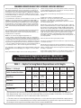
CONSUMER INFORMATION SHEET FOR PLAYGROUND SURFACING MATERIALS*
**The maximum fall height for this product is 108 in (274 cm).
We recommend using 9 in (23 cm) of Double Shredded Bark Mulch.**
5ft 6ft 7ft 9ft 10ft 11ft 12ft
-- 6in -- -- 9in 12in --
-- 6in 9in -- -- -- 12in
6in -- 9in 12in -- -- --
-- 6in 9in -- 12in -- --
-- -- -- -- 6in -- --
TABLE 1 — Depth of Surfacing Material Required Based on Fall Heights
Material/FallHeight
DoubleShreddedBarkMulch
WoodChips
FineSand
FineGravel
ShreddedTires***
(152cm)
(183cm) (213cm)
(274cm)
(305cm) (335cm) (366cm)
(15cm)
(23cm) (30cm)
(15cm) (23cm) (30cm)
(30cm)
(23cm)(15cm)
(15cm)
(23cm)
(30cm)
(15cm)
Select Protective Surfacing—One of the most important things you can
do to reduce the likelihood of serious head injuries is to install shock-
absorbing protective surfacing under and around your play equipment.
The protective surfacing should be applied to a depth that is suitable for
the equipment height in accordance with ASTM Specification F1292.
There are different types of surfacing to choose from; whichever product
you select, follow these guidelines:
Loose-Fill Materials—Maintain a minimum depth of 9 inches of loosefill
materials such as wood mulch/chips, engineered wood fiber (EWF), or
shredded/recycled rubber mulch for equipment up to 8 feet high; and
9 inches of sand or pea gravel for equipment up to 5 feet high. NOTE:
An initial fill level of 12 inches will compress to about a 9-inch depth
of surfacing over time. The surfacing will also compact, displace, and
settle, and should be periodically refilled to maintain at least a 9-inch
depth.
Use a minimum of 6 inches of protective surfacing for play equipment
less than 4 feet in height. If maintained properly, this should be
adequate. (At depths less than 6 inches, the protective material is too
easily displaced or compacted.)
NOTE: Do not install home playground equipment over
concrete, asphalt, or any other hard surface. A fall onto a hard surface
can result in serious injury to the equipment user. Grass and dirt are not
considered protective surfacing because wear and environmental factors
can reduce their shock absorbing effectiveness. Carpeting and thin mats
are generally not adequate protective surfacing. Ground level equipment
– such as a sandbox, activity wall, playhouse or other equipment that has
no elevated play surface – does not need any protective surfacing.
Use containment, such as digging out around the perimeter and/or lining
the perimeter with landscape edging. Don’t forget to account for water
drainage.
Check and maintain the depth of the loose-fill surfacing material. To
maintain the right amount of loose-fill materials, mark the correct level
on play equipment support posts. That way you can easily see when to
replenish and/or redistribute the surfacing.
Do not install loose fill surfacing over hard surfaces such as concrete or
asphalt.
Poured-In-Place Surfaces or Pre-Manufactured
Rubber Tiles—You may be interested in using surfacing other than loose-
fill materials – like rubber tiles or poured-in-place surfaces.
Installations of these surfaces generally require a professional and are
not “do-it-yourself” projects.
Review surface specifications before purchasing this type of surfacing.
Ask the installer/manufacturer for a report showing that the product has
been tested to the following safety standard: ASTM F1292 Standard
Specification for Impact Attenuation of Surfacing Materials within the
Use Zone of Playground Equipment. This report should show the specific
height for which the surface is intended to protect against serious head
injury. This height should be equal to or greater than the fall height –
vertical distance between a designated play surface (elevated surface
for standing, sitting, or climbing) and the protective surfacing below – of
your play equipment.
Check the protective surfacing frequently for wear.
Placements—Proper placement and maintenance of protective surfacing
is essential. Be sure to:
Extend surfacing at least 6 feet from the equipment in all directions.
For to-fro swings, extend protective surfacing in front of and behind the
swing to a distance equal to twice the height of the top bar from which
the swing is suspended.
For tire swings, extend surfacing in a circle whose radius is equal to the
height of the suspending chain or rope, plus 6 feet in all directions.

8
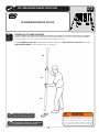
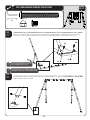
A cordless drill can be used for driving screws;
however, care should be taken not to over-tighten or strip screws.
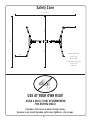
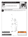
USE AT YOUR OWN RISK!
Safety Zone
USING A DRILL IS NOT RECOMMENDED
FOR DRIVING BOLTS.
25 feet 6 inches
36 feet
Playset dimensions:
Length 13’ 6”
Width 10’ 6”
Recommended play area:
Length 25’ 6”
Width 36’
6 feet
6 feet
18 feet
18 feet

9
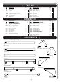
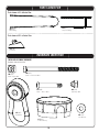
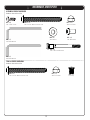
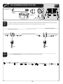
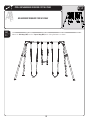
HARDWARE LIST
PARTS LIST
ID Item Description Qty
Box 1
ALE Bottom Pole 4
ALH Top Pole 4
Box 2
BKM Inside Bracket (with notches) 2
BKN Turn Bar 2
BKO Outside Bracket 2
ALF Middle Pole 4
ID Item Description Qty
BKQ A-Side Bracket 2
BKP B-Side Bracket 2
BKR Middle Swing Bar 1
BKS Outside Swing Bar 2
BKT Belt Swing 2
BKU Trapeze Swing 1
BFD Foot Cap 4
AMT Warning Sticker 1
ID Item Description Qty
All Hardware found in Box 2
BFF Swing Bar Assembly Hardware
EME 5/16” Square Nut 2
EMD 5/16” x 4 1/2” Hex Bolt 2
DZQ Pendulum 6
DZR 5/16” - 18 x 2” Bolt 4
AAN 5/16’’ Cap Nut 4
ASV 3” Round Cap 2
ARL 1/4’’ Washer 2
BFG A-Frame Assembly Hardware
DSA 1/4” x 20 Shoulder Bolt 4
ID Item Description Qty
BFG A-Frame Assembly Hardware
ADS 1/4” x 3/4” Screw 8
BFB 3/8” x 3 1/2” Button Head Screw 16
BFC 3/8” Acorn Nut 16
EQK 3/8” Washer 4
BTS 1/4” Barrel Nut 4
EEO 3/16” Allen Wrench 2
AOY 7/32” Allen Wrench 1
BFH Final Assembly Hardware
BFB 3/8” x 3 1/2” Button Head Screw 4
BFC 3/8” Acorn Nut 4
ARO Hole Cap 8
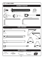
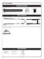
PARTS IDENTIFIER
Parts shown at 10% of Actual Size
BKM (x2)
Inside Bracket (with notches)
BKO (x2)
Outside Bracket
ALE (x4)
Bottom Pole
ALF (x4)
Middle Pole
ALH (x4)
Top Pole
BKQ (x2)
A-Side Bracket
BKP (x2)
B-Side Bracket
BKR (x1)
Middle Swing Bar
BKS (x2)
Outside Swing Bar
BKN (x2)
Turn Bar

10
PARTS IDENTIFIER
BKT (x2)
Belt Swing
Parts shown at 5% of Actual Size
SWING BAR ASSEMBLY HARDWARE
HardwareshownatActualSize
BKU (x1)
Trapeze Swing
HARDWARE IDENTIFIER
EME (x2)
5/16” Square Nut
EMD (x2)
5/16” x 4 1/2” Hex Bolt
DZQ (x6)
Pendulum
ASV (x2)
3” Round Cap
BFD (x4)
Foot Cap
Part shown at 25% of Actual Size
AAN (x4)
5/16’’ Cap Nut
DZR (x4)
5/16” - 18 x 2” Bolt
ARL (x2)
1/4’’ Washer

11
HARDWARE IDENTIFIER
A-FRAME ASSEMBLY HARDWARE
HardwareshownatActualSize
ADS (x8)
1/4” x 3/4” Screw
BFB (x16)
3/8” x 3 1/2” Button Head Screw
EQK (x4)
3/8” Washer
BTS (x4)
1/4” Barrel Nut
BFC (x16)
3/8” Acorn Nut
FINAL ASSEMBLY HARDWARE
HardwareshownatActualSize
BFB (x4)
3/8” x 3 1/2” Button Head Screw
BFC (x4)
3/8” Acorn Nut
ARO (x8)
Hole Cap
AOY (x1)
7/32” Allen Wrench
EEO (x2)
3/16” Allen Wrench
DSA (x4)
1/4” x 20” Shoulder Bolt

12
SWING BAR ASSEMBLY
HARDWARE REQUIRED
PARTS REQUIRED
TOOLS REQUIRED
SEC
1
Partsshownat10%ofActualSize
HardwareshownatActualSize
ASV (x2)
3” Round Cap
ARL (x2)
1/4’’ Washer
BKR (x1)
Middle Swing Bar
BKS (x2)
Outside Swing Bar
9/16” Wrench
(2)
Adjustable Wrench
(1)
Scrap Wood
(1)
DZQ (x6)
Pendulum
DZR (x4)
5/16” - 18 x 2” Bolt
AAN (x4)
5/16’’ Cap Nut
EMD (x2)
5/16” x 4 1/2” Hex Bolt
EME (x2)
5/16” Square Nut

TOOLS AND HARDWARE REQUIRED FOR THIS PAGE
13
SEC
1
SEC
1.1
Slide an Outside Swing Bar (BKS) into the Middle Swing Bar (BKR) as shown, and attach the swing bars together with
the hardware shown.
SEC
1.2
Slide the other Outside Swing Bar (BKS) into the other end of the Middle Swing Bar (BKR) as shown, and attach the swing bars
together with the hardware shown.
Note: Only finger tighten the hardware in this step.
!
Note: Only finger tighten the hardware in this step.
!
NO TOOLS REQUIRED FOR THIS PAGE
EME (x2)
ARL (x2)
EMD (x2)
DZQ (x2)
(Not actual size)
4 1/2”
(Not actual length)
BKR
BKS
EME
EMD
DZQ
EMD
EME
ARL
BKR
BKS
EME
EMD
EME
DZQ
EMD
ARL

TOOLS AND HARDWARE REQUIRED FOR THIS PAGE
14
SEC
NO NEW HARDWARE REQUIRED FOR THIS PAGE
SEC
1.3
1
9/16”
In order to seat the swing bar poles, strike each end of the swing bar very hard ve to six times on a piece of scrap wood
or cardboard. After the swing bar poles have been seated, tighten the hardware from steps 1.1 and 1.2.
ATTENTION: THIS STEP CANNOT BE REVERSED!
Note: Do not hit your feet with the pole
sections, as serious injury could occur.
!
Note: Tighten the hardware from steps 1.1 and 1.2
before continuing to the next step.
!
WARNING
The Poles must be seated together! They must
be struck on a hard surface ve to six times!
Failure to seat the Poles correctly could allow the
Poles to separate during use, which could lead
to serious personal injuries or property damage.
BKS
BKR
BKS

TOOLS AND HARDWARE REQUIRED FOR THIS PAGE
15
SEC
1
SEC
1.4
Attach the Swing Hardware to all of the brackets on the Swing Bar Assembly as shown.
SEC
1.5
Insert the 3” Round Caps (ASV) into the ends of the Swing Bar Assembly as shown.
ASV
ASV
DZQ (x4)
(Not actual size)
9/16” (x2)
ASV (x2)
(Not actual size)
DZR (x4)
AAN (x4)
DZR
DZQ
AAN
DZQ
DZR
AAN

16
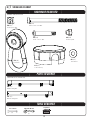
A-FRAME ASSEMBLY
HARDWARE REQUIRED
PARTS REQUIRED
TOOLS REQUIRED
SEC
2
Partsshownat10%ofActualSize
HardwareshownatActualSize
BKM (x2)
Inside Bracket (with notches)
BKO (x2)
Outside Bracket
ALE (x4)
Bottom Pole
ALF (x4)
Middle Pole
ALH (x4)
Top Pole
BKQ (x2)
A-Side Bracket
BKP (x2)
B-Side Bracket
BKN (x2)
Turn Bar
ADS (x16)
1/4” x 3/4” Screw
BFB (x16)
3/8” x 3 1/2” Button Head Screw
BFC (x16)
3/8” Acorn Nut
AOY (x1)
7/32” Allen Wrench
EEO (x2)
3/16” Allen Wrench
EQK (x4)
3/8” Washer
BTS (x4)
1/4” Barrel Nut
DSA (x4)
1/4” x 20” Shoulder Bolt
5/8” Wrench
(1)
Screwdriver
(1)
Scrap Wood
(1)
7/32” Allen Wrench 3/16” Allen Wrench
(included) (included)

TOOLS AND HARDWARE REQUIRED FOR THIS PAGE
17
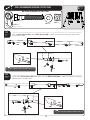
SEC
2
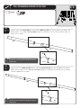
SEC
2.1
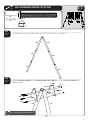
Align the hole in the Top Pole (ALH) with the slot in the Middle Pole (ALF) and slide the Middle Pole into the Top
Pole as shown. Insert a 1/4” x 3/4” Screw (ADS) through the small hole in the Top Pole and into the slot in the
Middle Pole as shown.
SEC
2.2
Align the hole in the Middle Pole (ALF) with the slot in the Bottom Pole (ALE) and slide the Bottom Pole into the
Middle Pole as shown. Insert a 1/4” x 3/4” Screw (ADS) through the small hole in the Middle Pole and into the
slot in the Bottom Pole as shown.
ADS
ALH
ALF
ALF
ALH
ALF
ALE
Note: The 1/4” x 3/4” Screw should be flush with the pole, but
will spin freely once installed. Do not jam the poles together
until instructed.
!
Note: The 1/4” x 3/4” Screw should be flush with the pole, but
will spin freely once installed. Do not jam the poles together
until instructed.
!
ADS
ALE
ALF
ADS (x2)
BKP (x2)
B-Side Bracket

TOOLS AND HARDWARE REQUIRED FOR THIS PAGE
18
SEC
2
SEC
2.3
WARNING
The Poles must be seated together! They must
be struck on a hard surface ve to six times!
Failure to seat the Poles correctly could allow the
Poles to separate during use, which could lead
to serious personal injuries or property damage.
Note: Do not hit your feet with the pole
sections, as serious injury could occur.
!
If the Top and Middle Poles (ALH & ALF) do not completely cover the slots on the Middle and Bottom Poles (ALF & ALE) after seating,
DO NOT COMPLETE ASSEMBLY. Call our Customer Service Department.
In order to seat the poles, strike each end of the pole very hard ve to six times on a piece of scrap wood or cardboard.
This must be done even if the poles cover the slots before seating has occurred.
ATTENTION: THIS STEP CANNOT BE REVERSED!
ALH
ALF
ALE
NO HARDWARE REQUIRED FOR THIS PAGE
Note: Repeat steps 2.1 through 2.3 to assemble all four
Pole Assemblies before moving to the next step.
!

TOOLS AND HARDWARE REQUIRED FOR THIS PAGE
19
SEC
2
SEC
2.5
Attach an Outside Bracket (BKO) and an Inside Bracket (with notches) (BKM) to the ends of two Top Poles (ALH) with the
hardware shown.
SEC
2.4
Lay two Pole Assemblies on the ground with the holes on the poles oriented as shown.
BFB (x4)
BFC (x4)
5/8”
7/32”
Note: Do not overtighten the hardware in this step.
!
ALH
ALF
ALE
ALF
ALH
ALE
BKO
BKM
BFB
BFB
BFC
BFC
Notches
ALH
ALH

TOOLS AND HARDWARE REQUIRED FOR THIS PAGE
20
SEC
3/16”
ALH
BKQ
BFB
BFB
BFC
BFC
BKQ
DSA
DSA
EQK
EQK
BTS
BTS
BKN
BKO
Straight Edge
2
SEC
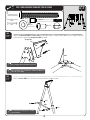
2.7
Attach a Turn Bar (BKN) to the assembled A-Frame with the hardware shown.
SEC
2.6
Attach an A-Side Bracket (BKQ) to a Top Pole (ALH) by nger tightening the hardware shown. Make sure the straight edge of the
A-Side Bracket is against the Outside Bracket (BKO) as shown.
Note: Repeat this step to assemble the B- Side Bracket (BKP) to the
other side of the assembly.
!
Note: Repeat steps 2.4 through 2.7 to assemble
the other A-Frame.
!
BFB (x8)
BFC (x8)
5/8”
7/32”
Note: Only finger tighten the hardware in this step.
!
BTS (x4)
DSA (x4)
EQK (x4)
3/8” Washer
La page est en cours de chargement...
La page est en cours de chargement...
La page est en cours de chargement...
La page est en cours de chargement...
La page est en cours de chargement...
La page est en cours de chargement...
-
 1
1
-
 2
2
-
 3
3
-
 4
4
-
 5
5
-
 6
6
-
 7
7
-
 8
8
-
 9
9
-
 10
10
-
 11
11
-
 12
12
-
 13
13
-
 14
14
-
 15
15
-
 16
16
-
 17
17
-
 18
18
-
 19
19
-
 20
20
-
 21
21
-
 22
22
-
 23
23
-
 24
24
-
 25
25
-
 26
26


Lifetime 290038 Le manuel du propriétaire
- Taper
- Le manuel du propriétaire
dans d''autres langues
- English: Lifetime 290038 Owner's manual
Documents connexes
-
Lifetime 290038 Le manuel du propriétaire
-
-
-
-
-
-
-


