Whirlpool WHAT122-2AW Manuel utilisateur
- Taper
- Manuel utilisateur

For questions about features, operation/performance, parts, or service, call: 1-800-207-1156.
In Canada, for assistance, installation, or service, call: 1-800-207-1156.
Table of Contents
WHAT081-HAW
WHAT121-HAW
WHAT141-HAW
WHAT101-HAW
WHAT081-1AW
WHAT101-1AW
WHAT102-2AW
WHAT121-1AW
WHAT122-2AW
WHAT142-2AW
W11263009A
Models:
AIR CONDITIONER SAFETY .......................................................................................................................................................... 2
INSTALLATION REQUIREMENTS .................................................................................................................................................. 3
Electrical Requirements—All Models .......................................................................................................................................... 3
Model BTUs—Cooling Only 115V 8000, 10000, 12000 .............................................................................................................. 3
Model BTUs—Cooling and Heating 115V 8000; 230V 10000, 12000, 14000 Cooling Only 230V 10000, 12000, 14000 ........... 3
Recommended Grounding Method ............................................................................................................................................. 3
Power Supply Cord—All Models ................................................................................................................................................. 4
Tools Required—All Models ........................................................................................................................................................ 4
Packing List ................................................................................................................................................................................ 4
Universal Wall—Sleeve Dimensions ............................................................................................................................................ 5
INSTALLATION INSTRUCTIONS .................................................................................................................................................... 6
Prepare Air Conditioner for Installation........................................................................................................................................ 6
Dual Intake Grille ......................................................................................................................................................................... 7
Trim Kit Installation Instructions................................................................................................................................................... 8
USING AIR CONDITIONER ............................................................................................................................................................ 9
Turning on the Air Conditioner ..................................................................................................................................................... 9
Selecting the Mode ..................................................................................................................................................................... 9
Features ....................................................................................................................................................................................... 9
Selecting the Fan Speed ............................................................................................................................................................. 9
Adjusting the Temperature ........................................................................................................................................................... 9
Using the Timer ......................................................................................................................................................................... 10
Changing Air Direction ............................................................................................................................................................... 10
Use of the Directional Louvers .................................................................................................................................................. 10
Normal Operating Sounds ......................................................................................................................................................... 10
Clean Filter Reminder ................................................................................................................................................................ 10
Using the Remote Control ......................................................................................................................................................... 11
Replacing the battery ................................................................................................................................................................ 11
AIR CONDITIONER CARE ............................................................................................................................................................ 12
Air Filter Removal ...................................................................................................................................................................... 12
Cleaning the Air Filter ................................................................................................................................................................ 12
Cleaning the Front Panel ........................................................................................................................................................... 12
Repairing Paint Damage ............................................................................................................................................................ 12
Winter Storage ........................................................................................................................................................................... 12
TROUBLESHOOTING ................................................................................................................................................................... 13
ASSISTANCE OR SERVICE .......................................................................................................................................................... 14
XLS PRODUCTS WARRANTY FOR WHIRLPOOL
®
AIR CONDITIONERS ................................................................................ 15
ROOM AIR CONDITIONER
Use and Care Guide

2
AIR CONDITIONER SAFETY
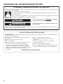
IMPORTA NT SAFETY INSTRUCTIONS
WARNING:
To reduce the risk of fire, electric shock, or injury when using your air conditioner, follow these basic precautions:
SAVE THESE INSTRUCTIONS
■ Plug into a grounded 3 prong outlet.
■ Do not remove ground prong.
■ Do not use an adapter.
■ This appliance is not intended for use by people (including
children) whose physical, sensory or mental capacities are
different or impaired or who lack the necessary experience
or knowledge/expertise to do so, unless such persons are
supervised or are trained to operate the appliance by a
person who accepts responsibility for their safety.
■ Do not use an extension cord.
■ Unplug air conditioner before servicing.
■ Use two or more people to move and install air conditioner.
■ Do not drink water collected in the water bucket.
■ Children should be supervised to ensure that they do not
play with the appliance.

3
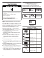
INSTALLATION REQUIREMENTS
Electrical Requirements—All Models
The electrical ratings for air conditioner are listed on the model
and serial number label. The model and serial number label is
located on the right-hand side of the air conditioner cabinet.
Specic electrical requirements are listed in the "Electrical
Requirements" sections. Follow the requirements for the type of
plug shown in these sections.
Model BTUs—Cooling Only 115 V 8000,
10000, 12000
All models
115 V − (103.5 min. - 126.5 max.)
If there is a "Single Circuit Only" label on the unit, use on a
dedicated single-outlet circuit only.
If a dedicated single-outlet circuit is not available, then it is
the customer’s responsibility to have a single-outlet circuit
installed by a qualied electrician.
If there is no "Single Circuit Only" label on the unit, the unit
may be used on any branch circuit of correct voltage and
adequate current protection rating.
8,000 BTU 115 V Cooling Only models
0-8 A
10 A time-delay fuse or circuit breaker
10,000-12,000 BTU 115 V Cooling Only models
0-12 A
15 A time-delay fuse or circuit breaker
Model BTUs—
Cooling and Heating 115 V 8000;
230V 10000, 12000, 14000
Cooling Only 230V 10000, 12000, 14000
10,000-14,000 BTU 230 V Cooling Only models
230 V (208 min. - 240 max.)
0-8 A
10 A time-delay fuse or circuit breaker
8,000 BTU 115 V and 10,000-14,000 BTU 230 V Cooling &
Heating models
4-15 A
20 A time-delay fuse or circuit breaker
If there is a "Single Circuit Only" label on the unit, use on a
dedicated single-outlet circuit only.
If a dedicated single-outlet circuit is not available, then it is
the customer’s responsibility to have a single-outlet circuit
installed by a qualied electrician.
If there is no "Single Circuit Only" label on the unit, the unit
may be used on any branch circuit of correct voltage and
adequate current protection rating.
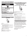
Recommended Grounding Method
This air conditioner must be grounded. This air conditioner is
equipped with a power supply cord having a grounded 3 prong
plug. To minimize possible shock hazard, the cord must be
plugged into a mating, grounded 3 prong outlet and grounded
in accordance with all local codes and ordinances. If a mating
outlet is not available, it is the customer’s responsibility to have a
properly grounded 3 prong outlet installed by a qualied electrical
installer. It is the customer’s responsibility:
To contact a qualied electrical installer.
To assure that the electrical installation is adequate and in
conformance with National Electrical Code, ANSI/NFPA 70—
latest edition, and all local codes and ordinances.
Copies of the standards listed may be obtained from:
National Fire Protection Association
1 Batterymarch Park
Quincy, MA 02269

4
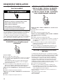
Power Supply Cord—All Models
NOTE: The air conditioner’s power supply cord may differ from
those shown.
The air conditioner is equipped with a power supply cord that is
required by UL. This power supply cord contains
state-of-the-art electronics that sense leakage current. If the cord
is damaged, the electronics detect leakage current and power
will be disconnected in a fraction of a second.
To test your power supply cord:
1. Plug power supply cord into a grounded 3 prong outlet.
2. Press RESET (on some models, a green light will turn ON).
3. Press TEST (listen for click; Reset button will trip, and on some
devices, a green light will turn OFF).
4. Press and release RESET (listen for click; Reset button will
latch, and on some devices, a green light will turn ON). The
power supply cord is ready for operation.
NOTES:
The Reset button must be pushed in for proper operation.
The power supply cord must be replaced if it fails to trip when
the test button is pressed or fails to reset.
Do not use the power supply cord as an OFF/ON switch. The
power supply cord is designed as a protective device.
A damaged power supply cord must be replaced with a new
power supply cord obtained from the product manufacturer
and must not be repaired.
The power supply cord contains no user-serviceable parts.
Opening the tamper-resistant case voids all warranty and
performance claims.
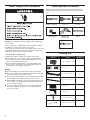
Tools Required—All Models
Gather the required tools and parts before starting installation.
Read and follow the instructions provided with any tools listed
here.
Phillips screwdriver
Tape measure
Scissors
Cordless drill
and 3/16" bit
Level
Pencil
Flathead screwdriver
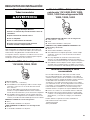
Packing List
1/2" Long Hex-head Screw
Grounding wire with tooth washer
Through-The-Wall Air Conditioner
Remote Control
Trim Frame 1 (Left&Right legs)
Trim Frame 2 (Top&Bottom legs)
Grille Aluminum
Rear plastic net
IMAGE PART QUANTITY
4
1
1
1
2
2
1
1
or
HI
G
H
MED
L
OW
A
U
T
O
SP
EED
D
RY
FA
N
AU
T
O
NEX
T
FAN
SP
EED
FILTER
SLEEP
M
O
DE
TIM
E
R
POWE
R
ECO
COOL
SLEEP
POWER
COOL
AUTO
MODE
TIMER
FAN
ONLY
ECO
DISPLAY
FAN
SPEED
SLEEP
POWER
COOL
HEAT
TIMER
FAN
ONLY
ECO
DISPLAY
FAN
SPEED

5
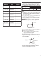
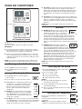
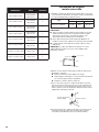
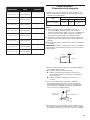
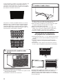
Universal Wall—Sleeve Dimensions
1. Identify the wall-sleeve brand installed in the wall, and make
sure that dimensions of wall-sleeve are as per the below table:
Type
Wall-sleeve Dimensions
Height Width Depth
Standard Dimension 15¾" 26" 16¾"
NOTE:
All wall sleeves, used to mount the new air conditioner must
be in sound structural condition and have a rear grille that
securely attached to the sleeve, or rear ange that serves as a
stop for the air conditioner.
If non-Whirlpool brand wall-sleeve installed, make sure that
the dimension is suitable for the product.
The selected wall-sleeve must be installed and fastened to
the wall with the screws.
IMPORTANT: When installation is complete, replacement unit
must have rearward slope as shown in below gure:
2. Remove the old air conditioner from wall sleeve and prepare as
follows:
Clean interior (Do not disturb seals).
Check the wall sleeve to make sure that it is securely
attached to the wall before installing.
Repair painted surface if needed.
3. If the ground wire hole does not exist, drill a 3/16" pilot hole for
the ground screw through the left hand side of the sleeve, in
a clear area about 3 inches max. back from the front edge as
shown in below gure:
4. Pull the loose end of the ground wire out of the front of
the sleeve and bend it away from the opening. This will be
attached to the air conditioner once installed.
Rear
Wall Sleeve
Level
1/4" to 5/16"
Front
Sleeve
W
all sleeve to unit
Gr
ounding.
3/16"Pilot Hole
3"
Max
1"
DIMENSIONS PART QUANTITY
1" x 3/4" x 14" Seal Sponge 2
1" x 3/8" x 14" Seal Sponge 2
1" x 3/8" x 25" Seal Sponge 3
1" x 1½"x 25" Seal Sponge 3
1" x 1½" x 14" Seal Sponge 2
1" x 1½" x 84" Seal Sponge 1
3¾" x 1½" x 4" Seal Cotton 4
3/4" x 1½" x 17" Seal Cotton 2

6
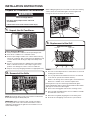
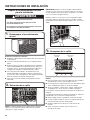
INSTALLATION INSTRUCTIONS
1. Unpack the Air Conditioner
Remove Packaging Materials:
Gently handle the air conditioner while unpacking the unit.
Place the air conditioner on a hard, at surface.
Remove tape and glue residue from surfaces before turning
ON the air conditioner. Rub a small amount of liquid dish soap
over the adhesive with the ngers. Wipe with a damp cloth
and dry.
Do not use sharp instruments, rubbing alcohol, ammable
uids, or abrasive cleaners to remove tape or glue. These
products can damage the surface of the air conditioner.
Dispose of/recycle packaging materials in an appropriate way.
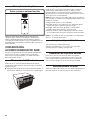
Prepare Air Conditioner for Installation
WARNING
Excessive Weight Hazard
Use two or more people to move and install
air conditioner.
Failure to do so can result in back or other injury.
NOTES:
This unit´s increased performance characteristics is the result
of having two rear intakes.
It is very important that installation instructions are followed
so the unit can operate at maximum efciency.
If there is an existing sleeve and rear grille, check whether the
dimension is suitable or not, otherwise replace them.
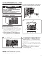
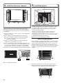
Existing Sleeves may have older single-sided intake grilles.
Single-sided intake grilles must be replaced with the dual intake
grille type as shown in the above gure.
Remove the existing grille and save the mounting screws.
Place the grille included with the new air conditioner towards
the inside rear of the sleeve.
Attach the new grille by aligning the four mounting holes.
Re-insert the self-tapping screws into the nylon retainers.
Left Intake
New Dual Intake Grille
Right
Intake
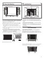
3. Replacement of the Grill
2. Removal of the Grille
NOTE: Single intake grille must be removed when used with the
dual intake Through The Wall (TTW) unit.
IMPORTANT: While removing the grille, avoid it from falling
by securing with a leash. This can be fastened from cord or
strapping looped through the grille and secured with a knot as
shown in above figure.
While holding the grille by the leash with one hand, the retaining
screws can be removed and the grille can be brought inside
through the front of the sleeve as shown below.

7
4
1
2
4
3
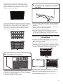
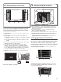
5. Install the Seal
1. Install the 1" x 3/8" x 25" long seal in the center at the top of
the sleeve. Remove the back paper and press into position.
2. Install the 1" x 3/8" x 14" seals to the left and right sides of the
sleeve.
3. Cut the 1" x 3/8" x 25" long seals to 14" long each and attach
to the vertical sections of the grille.
4. Install the 1/2" x 3½" x 1½" centering blocks one on each side
wall. Place in center of side wall with the tapered end facing
the opening.
5. Gently slide unit into sleeve.
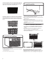
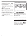
Dual Intake Grille
In cases, where the existing sleeve is a dual intake grille, the
existing grille may be left in place.
Make sure the outer 3½" to 4½" louvers are angled from the
left and right sides of the sleeve toward the center, as shown in
below gure. This provides proper ow of outside air into the unit.
From the installation kit, apply two 1" x 3/4" x 14" seals along the
at metal ange of the condenser, as shown in below gure:
Seal
Seal
In cases, where the dual intake grille cannot be mounted directly
to the sleeve it is desirable to attach the grille to the back of the
TTW unit to the hole predrilled in the unit.
1. Attach the 2 seals (1" x 3/8" x 14"), as shown in above gure.
2. Position the grille over the rear of the unit to make sure that:
The double set of screw holes are at the bottom.
The intake ns on either side are pointed away from the
unit.
3. Align the top of the grille with the top of the unit. The overhang
on each side is equal.
4. If the unit has not been predrilled (some models), drill 4-1/8"
holes through the grille and into the side ange of the unit
approximately 1½" to 2" from the top and bottom, as shown in
below gures. (Do not break the copper pipe.)
5. Install 4-#8 self-tapping screws to afx the grille to the unit.
6. Insert the unit into the sleeve.
Grille Screws
Location
seal
seal
4. Direct Unit Mounting
# 8 Screw
1/8 Hole
Grille &
Flange

8
1. Install new unit into wall sleeve.
2. To attach ground wire to the new unit, remove the screw from
the front, left side.
3. Assemble and install the trim frame.
6. Install the Air Conditioner
1. Attach the one end of the ground wire inside the sleeve with
screw according to preparation instruction.
2. Before sliding unit all the way back remove second screw from
left side of unit.
3. Remove plastic washer from screw.
4. Attach the other end of the ground wire to the unit with screw
as shown above. Make sure that the toothed washer is against
the cabinet.
5. Slide unit completely to the rear.
Trim Kit Installation Instructions
1. Install the 1" x 1" x 84" long stuffer seal between the wall
sleeve and the unit. A at-bladed screwdriver or putty knife is
needed.
2. Assemble the trim frame by inserting the top and bottom
pieces into side pieces and snapping into place.
3. Pull the cord through the trim frame and slide the trim over the
unit until ush with the wall.
Energy saving suggestion: In order to reach the maximum
energy saving and comfortability, it is necessary to use an
appropriately sized cover to provide additional insulation and air
sealing when the unit is not in use during the off-using-season.
HIGH
COOL
DRY
FAN
AUTO
NEXT
MED
LOW
AUTO
SPEED
FAN
SPEED
SPLEEPFILTER
TIMER
ECO MODE POWER
7. Install Ground Wire
Insert the unit with the seal into the sleeve pushing it all the way
to the rear, making sure the seals are against the rear grille. The
seals are necessary to reduce recirculation of hot air into the
intakes which would reduce system performance.
An option is to purchase 3/4" diamond cut aluminum grille and
cut it to t inside the sleeve. Secure it with screws. Attach the
dual intake grill directly to the back of the unit. Slide the entire
unit into the sleeve and seal with the stufng seal supplied with
the kit.
HIGH
COOL
DRY
FAN
AUTO
NEXT
MED
LOW
AUTO
SPEED
FAN
SPEED
SPLEEP
FILTER
TIMER
ECO MODE POWER

9
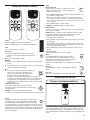
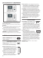
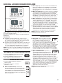
Turning on the Air Conditioner
1. Press POWER to turn ON air conditioner.
2. Press POWER again to turn OFF the air
conditioner.
Selecting the Mode
1. Press MODE button to cycle through the
various modes.
2. Choose modes: Cool, Dry, Fan, Auto or Heat.
Cool mode: The cooling function allows the air
conditioner to cool the room and at the same
time reduces air humidity. Press the MODE
button to activate the cooling function. Press
the up or down arrow button to adjust the
temperature.
Dry Mode: This function reduces the humidity
of the air to make the room more comfortable.
Press MODE button to set the DRY mode. An
automatic function of alternating cooling cycles
and air fan is activated.
Fan Mode: In this mode, only fan runs to provide ventilation.
Press MODE button to set the FAN mode. Press FAN SPEED
to select High, Med, or Low. The remote control stores the
speed set in the previous mode of operation.
USING AIR CONDITIONER
Features
ECO Button: When the unit is in ECO mode,
the light will turn ON. In ECO mode, the unit
will turn-off once the room is cooled to the
user set temperature. The fan motor will run
for 20 to 40 seconds and then it will stop, this will repeat
to provide more comfortable feeling and save energy. The
compressor will turn back on when the room temperature
rises above the set temperature. Press ECO to turn ECO
feature on and off. When the unit is in ECO mode, the light will
turn on.
SLEEP Button: Automatically adjusts the
temperature and fan speed to make the room
more comfortable during the night. Press and
hold the SLEEP button for 10 seconds until the sleep light
turns on. All of the left lights will turn off. For heat mode,
temperature will automatically decrease by 1.8°F (1°C) every
30-60 minutes. At most, the temperature will change six
times until the temperature reaches 75°F (24°C). The set
temperature will automatically raise by 1.8°F (1°C) every 30-
60 minutes. At most, the temperature will change six times
until the temperature reaches 82°F (28°C). Running time
depends upon the set temperature.
NOTE: After 5 seconds, display will show the current room
temperature.
Selecting the Fan Speed
1. Press FAN SPEED button until the LED indicator
for the desired setting is lit.
2. Choose Low, Med, or High.
Low—Low fan speed
Med—Normal fan speed
High—Maximum fan speed
NOTES:
Auto fan speed and temperature cannot be
selected in Fan Only mode.
In ECO and SLEEP modes, Auto fan speed is
selected automatically.
After 5 seconds, the display will show the current
room temperature.
Adjusting the Temperature
Press the up arrow button to increase the set
temperature.
Press the down arrow button to decrease the set
temperature.
NOTE: After 5 seconds, the display on the air
conditioner control panel will show the current room temperature.
Air Conditioner
Controls
For Heating model
For Cooling model
COOL
MODE
TIMER
SLEEPFILTER
ECO
AUTO
SPEED
LOW
MED
HIGH
DRY
FAN
AUTO
MODE
FAN
SPEED
POWER
COOL
MODE
TIMER
SLEEPFILTER
ECO
AUTO
SPEED
LOW
MED
HIGH
DRY
FAN
AUTO
MODE
FAN
SPEED
POWER
HEAT
MODESPEED
MODESPEED
MODESPEED
MODESPEED
HEAT
MODE
AUTO
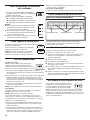
Operating air conditioner properly helps you to obtain the best
possible results.
This section explains proper air conditioner operation.
IMPORTANT:
If you turn OFF the air conditioner, wait at least 3 minutes
before turning it back on. This is to avoid the air conditioner
from blowing a fuse or tripping a circuit breaker.
Do not try to operate the air conditioner in the Cool mode
when outside temperature is below 65°F (18°C). The inside
evaporator coil will freeze up, and the air conditioner will not
operate properly.
NOTE: In the event of a power failure, the air conditioner will
operate at the previous settings when the power is restored.
Auto Mode: In AUTO mode, the unit automatically chooses
the fan speed and the mode of operation (COOL, DRY or
FAN). In this mode the fan speed and the temperature are set
automatically according to the room temperature (tested by
the temperature sensor which is incorporated in the indoor
unit).
Heat Mode: The heating function allows the air conditioner to
heat the room. Press the MODE button to activate the heating
function. To optimize the function of the air conditioner,
adjust the temperature and the speed by pressing the button
indicated.
NOTE: After 5 seconds, display will show the current room
temperature.
AUTO
SPEED

10
Using the Timer
Delayed Shutoff:
Use the TIMER button to set the air conditioner
to turn off automatically after 0.5- to 24-hour
delay (the air conditioner must be on):
1. Press TIMER button. The display will show
remaining time before the air conditioner will turn off.
2. Press the up or down arrow button to change the delayed
shutoff time from 0.5 to 24 hours. The time can be set in 0.5-
hour increments below 10 hours and 1-hour increments for 10
hours or above.
3. Press TIMER button again to conrm setting.
NOTE: The Set light will turn on while setting.
Delayed Start:
It can be set to automatically turn off or on in 0.5-24 hours delay.
NOTE: After the set delay, the air conditioner will turn on with
the previous settings. Change the mode, fan speed, and/or
temperature before setting the timer, if desired.
1. Turn off the air conditioner.
2. Press TIMER button. Set the temperature by pressing the up or
down arrow button.
3. Press TIMER button a second time to set the rest time. Press
the up or down arrow button to change the delay time from 0.5
to 24 hours, then press TIMER button again.
4. Press TIMER button again while the time remaining is shown
on the display.
To Cancel Timer:
After the timer has been set, press TIMER button.
Changing Air Direction
Air Deector Air DeectorHorizontal Wheel
Use of the Directional Louvers
Normal Operating Sounds
When the air conditioner is operating normally, you may hear
sounds such as:
Droplets of water hitting the condenser, causing a pinging or
clicking sound. The water droplets help cool the condenser.
Air movement from the fan.
Clicks from the thermostat cycle.
Vibrations or noise due to poor wall or window construction.
A high-pitched hum or pulsating noise caused by the modern
high-efciency compressor cycling ON and OFF.
Water will collect in the base pan during rain or days of high
humidity. The water may overow and drip from the outside
part of the unit.
To direct the airow, use the horizontal wheel to control the
horizontal direction and the air deector to control the vertical
direction.
MODESPEED
MODESPEED
Clean Filter Reminder
To help maximize energy efciency, this air
conditioner features a Clear Filter reminder.
After 500 hours of operation, FILTER will
illuminate as a reminder that it is time to
clean the lter. Once the light is illuminated, it can be turned off
by pressing the FILTER button. See the "Air Conditioner Care"
section for instructions on how to clean the lter.
MODESPEED
MODESPEED

11
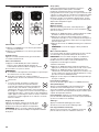
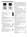
Using the Remote Control
Power
1. Press POWER to turn ON air conditioner.
2. Press POWER again to turn OFF the air conditioner.
Cool
Press COOL to enter Cool mode.
Fan Speed
1. Press FAN SPEED until the bar LED on the air
conditioner control panel display for the desired
setting.
2. Choose Low, Medium, or High.
NOTES:
Auto fan speed and Temperature cannot be selected in Fan
mode.
In Energy Saver (on some models) and Cool modes, Auto fan
speed is selected automatically.
Adjusting Temperature
Press the up arrow button to increase the set
temperature. Press the down button to decrease the
set temperature.
NOTE: After 5 seconds, the display on the air
conditioner control panel will show the current room temperature.
Timer
Delayed Shutoff:
Use the timer to set the air conditioner to turn off
automatically after a 0.5- to 24-hour delay (the air
conditioner must be ON):
1. Press TIMER. The display will show remaining time before the
air conditioner will turn OFF.
2. Press the up or down arrow button to change the delayed
shut-off time from 0.5 to 24 hours. The time can be set in 0.5-
hour increments below 10 hours and 1-hour increments for 10
hours or above.
3. Press TIMER again to confirm setting.
NOTE: The Set light will turn on while setting.
Delayed Start:
You can also set the air conditioner to turn on automatically after
a 0.5- to 24-hour delay.
NOTE: After the set delay, the air conditioner will turn on with
the previous settings. Change the mode, fan speed, and/or
temperature before setting the timer, if desired.
1. Turn OFF the air conditioner.
2. Press TIMER. Set the temperature by pressing the up or down
arrow button.
3. Press TIMER a second time to set the rest time. Press the up
or down arrow button to change the delay time from 0.5 to 24
hours, then press TIMER again.
4. Press TIMER again while the time remaining is shown on the
display.
To Cancel Timer:
After the timer has been set, press TIMER.
POWER COOL
SLEEP
TIMER
ECO
DISPLAY
AUTO
MODE
FAN
ONLY
FAN
SPEED
Eco
Conserves energy by turning OFF compressor
when room reaches desired temperature.
The fan motor will run for 20 to 40 seconds
and then it will stop, this will repeat to
provide more comfortable feeling and save energy. The
compressor will turn back ON when the room temperature
rises above the set temperature. Press ECO to turn Eco
feature ON and OFF. When the unit is in Eco mode, the light
will turn ON.
Sleep
Automatically adjusts the temperature and fan speed
to make the room more comfortable during the night.
Press and hold the SLEEP button for 10 seconds until
the sleep light turns on. All of the left lights will turn off. The set
temperature will automatically raise by 1.8°F (1˚C) every 30-60
minutes. At most, the temperature will change six times until the
temperature reaches 82°F (28°C). Running time depends upon
the set temperature.
POWER COOL
SLEEP
TIMER
ECO
DISPLAY
AUTO
MODE
FAN
ONLY
FAN
SPEED
SLEEP
POWER
COOL
HEAT
TIMER
FAN
ONLY
ECO
DISPLAY
FAN
SPEED
SLEEP
POWER
COOL
AUTO
MODE
TIMER
FAN
ONLY
ECO
DISPLAY
FAN
SPEED
Auto:
Press AUTO MODE to enter into Auto mode. In
this mode, the fan speed and temperature are set
automatically according to the room temperature as
tested by the indoor temperature sensor.
Heat: Press the HEAT button to Heat mode. It is for heating
model.
Display:
Press DISPLAY to switch on/off all lights or the LED
display.
Fan only:
Press the Fan Only button to enter Fan Only mode.
POWER
COOL
SLEEP
TIMER
ECO
DISPLAY
AUTO
MODE
FAN
ONLY
FAN
SPEED
POWER
COOL
SLEEP
TIMER
ECO
DISPLAY
AUTO
MODE
FAN
ONLY
FAN
SPEED
POWER COOL
SLEEP
TIMER
ECO
DISPLAY
AUTO
MODE
FAN
ONLY
FAN
SPEED
POWER COOL
SLEEP
TIMER
ECO
DISPLAY
AUTO
MODE
FAN
ONLY
FAN
SPEED
POWER COOL
SLEEP
TIMER
ECO
DISPLAY
AUTO
MODE
FAN
ONLY
FAN
SPEED
POWER COOL
SLEEP
TIMER
ECO
DISPLAY
AUTO
MODE
FAN
ONLY
FAN
SPEED
POWER COOL
SLEEP
TIMER
ECO
DISPLAY
AUTO
MODE
FAN
ONLY
FAN
SPEED
Replacing the battery
Use a small Phillips screwdriver to loosen the battery cover
screw. Slide the battery cover down with two thumbs to remove.
Remove and properly dispose of old batteries, then replace with
two new AAA batteries. Replace the battery cover and tighten the
screw.
Remove and replace batteries

12
The air conditioner is designed to give you many years of
dependable service. This section tells you how to clean and care
for your air conditioner properly.
AIR CONDITIONER CARE
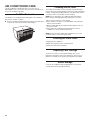
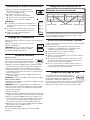
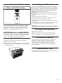
Air Filter Removal
The air lter is located behind the intake grille of air conditioner.
Remove the air lter as follows:
Remove the lter by pulling down the indents of the lter door
on the front of the unit as shown in below gure.
C
O
OL
M
ODE
FILT
ER
E
CO
A
UT
O
S
P
E
E
D
L
OW
M
E
D
HI
GH
D
RY
FA
N
A
U
T
O
MO
D
E
FAN
SPE
ED
POWER
Cleaning the Air Filter
The air lter is removable for easy cleaning. A clean lter helps
remove dust, lint, and other particles from the air and is important
for best cooling and operating efciency. Check the lter at least
once per month to see whether it needs cleaning.
NOTE: Do not operate the air conditioner without the lter in
place. Doing so will degrade the unit performance over time.
1. Use a vacuum cleaner to clean air lter.
2. If the air lter is very dirty, use the liquid dish soap and warm
water to wash the lter.
3. Rinse the lter properly and shake the lter gently to remove
the excess water.
4. Let the lter dry completely before placing it into the air
conditioner to ensure maximum efciency.
NOTE: Do not wash the air lter in the dishwasher or use any
chemical cleaners; it may damage the lter.
Cleaning the Front Panel
1. Unplug the air conditioner.
2. Wipe the front panel with a soft, damp cloth.
3. Air dry the front panel completely.
Repairing Paint Damage
Check once or twice a year for paint damage. This is very
important, especially in areas near saltwater or where rust is a
problem. If needed, touch up with a good grade enamel paint.
Winter Storage
Cover the air conditioner with an appropriate cover to block
outside air ow and to provide insulation.

13
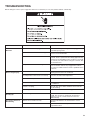
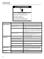
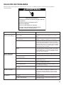
TROUBLESHOOTING
Before calling for service, try the suggestions below to see whether you can solve problem without outside help.
PROBLEM POSSIBLE CAUSES RECOMMENDED SOLUTIONS
The Air Conditioner Will
Not Start
The air conditioner is unplugged. Make sure that the power supply cord is plugged into a
grounded 3 prong outlet.
The fuse is blown/circuit breaker is tripped. Check the house fuse/circuit breaker box and replace
the fuse or reset the breaker.
Power failure. The unit will automatically restart when power is
restored. There is a protective time delay (approximately
3 minutes) to avoid tripping of the compressor overload.
The unit may not start normal cooling for 3 minutes after
it is turned back on.
The power cord reset button is tripped. Press the reset button located on the power cord plug.
If the reset button will not stay engaged, discontinue
use of the air conditioner and contact a qualied service
technician.
The Air Conditioner Is
Not Cooling Properly
Airow is restricted. Make sure that there are no curtains, blinds, or furniture
blocking the front of the air conditioner.
The temperature control is not set correctly. Lower the set thermostat temperature.
The air lter is dirty. Clean the lter. See the “Air Conditioner Care” section.
The room is too warm. Allow time for the room to cool down after turning on the
air conditioner.
Cold air is escaping. Close all open doors and/or windows where warm air
may be entering.
The cooling coils are frozen. See “The Air Conditioner Is Freezing Up” below.
The Air Conditioner Is
Freezing Up
Ice is blocking the airow. Turn off the unit and allow it to thaw until the ice has
melted, then operate on a higher fan speed. If this
continues to occur, contact customer service for
additional help.
The Remote Control Is
Not Working
Batteries are inserted incorrectly. Check that the batteries are inserted in the correct
direction.
Batteries are dead. Replace the batteries and dispose of them in a
responsible manner.

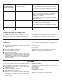
14
Before calling for assistance or service, please check the
"Troubleshooting" section. It may save you the cost of a service
call. If you still need help, follow the instructions below.
When calling, please know the purchase date and the complete
model and serial numbers of the appliance. This information will
help us to better respond to the request.
Call XLS Products Customer Service toll free:
1-800-207-1156.
Our consultants provide assistance with:
Features and specications on our full line of appliances.
Installation information.
Use and maintenance procedures.
Accessory and repair parts.
Specialized customer assistance.
Referrals to local dealers, repair parts distributors, and service
companies. XLS Products-designated service technicians
are trained to fulll the product warranty and provide after-
warranty service, anywhere in the United States.
For further assistance:
If you need further assistance, you can write to XLS Products
with any questions or concerns at:
XLS Products, Inc.
Customer Service
P.O. Box 16262
Philadelphia, PA 19114-0262
Please include a daytime phone number in your correspondence.
Call XLS Products Customer Service toll free:
1-800-207-1156.
Our consultants provide assistance with:
Features and specications on our full line of appliances.
Use and maintenance procedures.
Accessory and repair parts.
Referrals to local dealers, repair parts distributors, and service
companies. XLS Products-designated service technicians
are trained to fulll the product warranty and provide after-
warranty service, anywhere in Canada.
For further assistance:
If you need further assistance, you can write to XLS Products
with any questions or concerns at:
XLS Products, Inc.
Customer Service
P.O. Box 16262
Philadelphia, PA 19114-0262
Please include a daytime phone number in your correspondence.
ASSISTANCE OR SERVICE
In the USA
In Canada
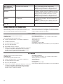
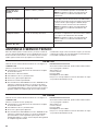
PROBLEM POSSIBLE CAUSES RECOMMENDED SOLUTIONS
Water Is Dripping
From the Unit on the
Outdoor Side
The weather is hot and humid. This is normal during periods of high humidity.
NOTE: Do not drill a hole into the bottom of the metal
base pan; doing so will reduce cooling performance.
Water Is Dripping Inside
the Room
The air conditioner is not properly leveled. The air conditioner should slope slightly downward
toward the outside. Level the air conditioner to provide
a downward slope toward the outside to ensure proper
drainage. See the “Installation Instructions” section.
NOTE: Do not drill a hole into the bottom of the metal
base pan; doing so will reduce cooling performance.
Water Collects in the
Base Pan
Moisture removed from the air is collecting
in the base pan.
This is normal. Water that collects in the base pan will
evaporate to the outside air. This helps with the unit's
cooling process.
NOTE: Do not drill a hole into the bottom of the metal
base pan; doing so will reduce cooling performance.
Digital display reads
"E1", "E2"
A sensor has failed. Contact customer service.

15
XLS PRODUCTS WARRANTY FOR
WHIRLPOOL
®
AIR CONDITIONERS
ONE YEAR LIMITED WARRANTY
For one year from the date of purchase, when this product is operated and maintained according to instructions attached to or
furnished with the product, XLS Products will pay for product replacement (at our discretion) to correct defects in materials or
workmanship.
ITEMS XLS PRODUCTS WILL NOT PAY FOR
1. Service calls to correct the installation of your product, instruct you how to use your product, to replace house fuses or reset circuit
breakers, replace or clean lters, or correct house wiring.
2. Service calls to repair or replace air lters. Those consumable parts are excluded from warranty coverage.
3. Repairs when your product is used for other than normal, single-family household use.
4. Damage resulting from accident, alteration, misuse, abuse, re, ood, acts of God, improper installation, installation not in
accordance with electrical or plumbing codes, or use of products not approved by XLS Products.
5. Replacement parts or repair labor costs for units operated outside the United States or Canada.
6. Pickup and delivery. This product is designed to be repaired in the home.
7. Repairs to parts or systems resulting from unauthorized modications made to the appliance.
8. Expenses for travel and transportation for product service in remote locations.
9. The removal and reinstallation of your appliance if it is installed in an inaccessible location or is not installed in accordance with
published installation instructions.
DISCLAIMER OF IMPLIED WARRANTIES; LIMITATION OF REMEDIES
CUSTOMER’S SOLE AND EXCLUSIVE REMEDY UNDER THIS LIMITED WARRANTY SHALL BE PRODUCT REPAIR AS PROVIDED
HEREIN. IMPLIED WARRANTIES, INCLUDING WARRANTIES OF MERCHANTABILITY OR FITNESS FOR A PARTICULAR PURPOSE,
ARE LIMITED TO ONE YEAR OR THE SHORTEST PERIOD ALLOWED BY LAW. XLS PRODUCTS SHALL NOT BE LIABLE FOR
INCIDENTAL OR CONSEQUENTIAL DAMAGES. SOME STATES AND PROVINCES DO NOT ALLOW THE EXCLUSION OR
LIMITATION OF INCIDENTAL OR CONSEQUENTIAL DAMAGES, OR LIMITATIONS ON THE DURATION OF IMPLIED WARRANTIES OF
MERCHANTABILITY OR FITNESS, SO THESE EXCLUSIONS OR LIMITATIONS MAY NOT APPLY TO YOU. THIS WARRANTY GIVES
YOU SPECIFIC LEGAL RIGHTS AND YOU MAY ALSO HAVE OTHER RIGHTS, WHICH VARY, FROM STATE TO STATE OR PROVINCE
TO PROVINCE.
Outside the 50 United States and Canada, this warranty does not apply. Contact your authorized XLS Products dealer to determine if
another warranty applies.
If you need service, rst see the “Troubleshooting” section of the Use & Care Guide. After checking “Troubleshooting,” additional help
can be found by checking the “Assistance or Service” section or by calling XLS Products. In the U.S.A., call 1-800-207-1156.
In Canada, call 1-800-207-1156.
Keep this book and your sales slip together for future reference.
You must provide proof of purchase or installation date for
in-warranty service.
Write down the following information about your air conditioner
to better help you obtain assistance or service if you ever need
it. You will need to know your complete model number and serial
number. You can nd this information on the model and serial
number label located on the product.
Dealer name _____________________________________________
Address _________________________________________________
Phone number ___________________________________________
Model number ___________________________________________
Serial number ____________________________________________
Purchase date ___________________________________________

Pour des questions à propos des caractéristiques, du fonctionnement/rendement, des pièces ou du service, composer le: 1800207-1156.
Au Canada, pour assistance, installation ou service, composer le: 1800207-1156.
Table des matières
WHAT081-HAW
WHAT121-HAW
WHAT141-HAW
WHAT101-HAW
WHAT081-1AW
WHAT101-1AW
WHAT102-2AW
WHAT121-1AW
WHAT122-2AW
WHAT142-2AW
W11263009A
Modèles:
CLIMATISEUR DE PIÈCE
Guide d’utilisation et d’entretien
SÉCURITÉ DU CLIMATISEUR...................................................................................................................................................... 17
EXIGENCES D’INSTALLATION .................................................................................................................................................... 18
Spécications électriques – tous les modèles .......................................................................................................................... 18
Modèles de 115 V à 8000, 10000, 12000BTU avec refroidissement seulement ................................................................... 18
Modèles de 115 V à 8000BTU et de 230V à 10000, 12000 et 14000BTU avec refroidissement et chauffage;
de230 V à 10000, 12000, 14000BTU avec refroidissement seulement................................................................................ 18
Méthode recommandée de liaison àlaterre ............................................................................................................................. 18
Cordon d’alimentation – touslesmodèles ................................................................................................................................ 19
Outils nécessaires – Tous les modèles ...................................................................................................................................... 19
Liste d’articles .......................................................................................................................................................................... 19
Dimensions de la gaine muraleuniverselle................................................................................................................................ 20
INSTRUCTIONS D’INSTALLATION .............................................................................................................................................. 21
Préparer le climatiseur pour l’installation................................................................................................................................... 21
Grille à entrée double ................................................................................................................................................................ 22
Instructions d’installation de la trousse de garniture ................................................................................................................. 23
UTILISATION DU CLIMATISEUR ................................................................................................................................................. 24
Mettre en marche le climatiseur ................................................................................................................................................ 24
Sélectionner le mode ................................................................................................................................................................. 24
Caractéristiques ........................................................................................................................................................................ 24
Sélectionner la vitesse duventilateur ........................................................................................................................................ 25
Réglage de la température ........................................................................................................................................................ 25
Utiliser la minuterie .................................................................................................................................................................... 25
Changement de direction de l’air .............................................................................................................................................. 25
Bruits de fonctionnement normaux ........................................................................................................................................... 25
Rappel de nettoyage du ltre .................................................................................................................................................... 25
Utilisation de la télécommande ................................................................................................................................................. 26
Remplacer la pile ....................................................................................................................................................................... 27
ENTRETIEN DU CLIMATISEUR ................................................................................................................................................... 27
Retirer le ltre à air ..................................................................................................................................................................... 27
Nettoyage du ltre à air ............................................................................................................................................................. 27
Nettoyage du panneau avant .................................................................................................................................................... 27
Rénovation de la peinture .......................................................................................................................................................... 27
Rangement pour l’hiver ............................................................................................................................................................. 27
DÉPANNAGE ................................................................................................................................................................................. 28
ASSISTANCE OU SERVICE .......................................................................................................................................................... 29
GARANTIE DE XLS PRODUCTS POUR LESCLIMATISEURSWHIRLPOOL
®
.......................................................................... 30

17
SÉCURITÉ DU CLIMATISEUR
Risque possible de décès ou de blessure grave si vous ne
suivez pas immédiatement les instructions.
Risque possible de décès ou de blessure grave si vous
ne suivez pas les instructions.
Tous les messages de sécurité vous diront quel est le danger potentiel et vous disent comment réduire le risque de blessure et
ce qui peut se produire en cas de non-respect des instructions.
Votre sécurité et celle des autres est très importante.
Nous donnons de nombreux messages de sécurité importants dans ce manuel et sur votre appareil ménager. Assurez-vous de
toujours lire tous les messages de sécurité et de vous y conformer.
AVERTISSEMENT
DANGER
Voici le symbole d’alerte de sécurité.
Ce symbole d’alerte de sécurité vous signale les dangers potentiels de décès et de blessures graves à vous
et à d’autres.
Tous les messages de sécurité suivront le symbole d’alerte de sécurité et le mot “DANGER” ou
“AVERTISSEMENT”. Ces mots signifient :
Pour réduire les risques d'incendie, de choc électrique ou des blessures lors de l'utilisation du
climatiseur, prendre quelques précautions fondamentales, y compris les suivantes:
CONSERVEZ CES INSTRUCTIONS
■ rancer sur une prise alvéoles reliée la terre .
■ Ne pas enlever la broce de liaison la terre .
■ Ne pas utiliser un adaptateur.
■ et appareil ne convient pas une utilisation par des
personnes copris des enfants dont les capacités
psiques sensorielles ou entales sont différentes ou
réduites ou qui ne possdent pas l’epérience les
connaissances ou l’epertise nécessaire oins d’être
supervisées ou d’avoir reu des instructions concernant
l’utilisation par une personne responsable de leur sécurité.
■ Ne pas utiliser un cble de rallone .
■ ébrancer le cliatiseur avant lentretien .
■ tiliser deu ou plus de personnes pour déplacer et
installer le cliatiseur .
■ Ne pas boire l’eau recueillie dans le bac.
■ Les enfants doivent être placés sous surveillance afin de
s’assurer qu’ils ne jouent pas avec l’appareil.
IMPORTANTES INSTRUCTIONS DE SÉCURITÉ
AVERTISSEMENT:

18
EXIGENCES D’INSTALLATION
Spécications électriques –
tous les modèles
Les caractéristiques électriques du climatiseur sont indiquées sur
la plaque signalétique. La plaque signalétique des numéros de
modèle et de série est située du côté droit du climatiseur.
Les exigences électriques spéciques sont indiquées dans la
section “Spécications électriques”. Suivre les recommandations
pour ce type de prise électrique indiquées dans ces sections.
Modèles de 115 V à 8000, 10000,
12000BTU avec refroidissement
seulement
Tous les modèles
115 V – (103,5min. à 126,5 max.)
Si une étiquette “Circuit indépendant seulement” est apposée
sur l’appareil, utiliser l’appareil sur un circuit où rien d’autre
n’est branché.
Si ce n’est pas possible, il incombe à l’utilisateur de faire
installer par un électricien qualié un circuit où l’appareil
pourra être branché seul.
Si aucune étiquette “Circuit indépendant seulement” n’est
apposée sur l’appareil, l’appareil peut être branché à toute
prise offrant la bonne tension et la protection adéquate.
Modèle de 115 V à 8000BTU avec refroidissement seulement
0-8 A
Fusible ou disjoncteur temporisé de 10 A
Modèle de 115 V à 10000 – 12000BTU avec refroidissement
seulement
0-12 A
Fusible ou disjoncteur temporisé de 15 A
AVERTISSEMENT
Risque de choc électrique
Brancher sur une prise à 3 alvéoles reliée à la terre.
Ne pas enlever la broche de liaison à la terre.
Ne pas utiliser un adaptateur.
Ne pas utiliser un câble de rallonge.
Le non-respect de ces instructions peut causer
un décès, un incendie ou un choc électrique.
Modèles de 115 V à 8000BTU et de
230V à 10000, 12000 et 14000BTU
avec refroidissement et chauffage;
de230 V à 10000, 12000, 14000BTU
avec refroidissement seulement
Modèle de 230 V à 10000 – 14000BTU avec refroidissement
seulement
230 V (208min. à 240 max.)
0-8 A
Fusible ou disjoncteur temporisé de 10 A
Modèles de 115 V à 8000BTU et 230 V à 10000 – 14000BTU
avec refroidissement et chauffage
4-15 A
Fusible ou disjoncteur temporisé de 20 A
Si une étiquette “Circuit indépendant seulement” est apposée
sur l’appareil, utiliser l’appareil sur un circuit où rien d’autre
n’est branché.
Si ce n’est pas possible, il incombe à l’utilisateur de faire
installer par un électricien qualié un circuit où l’appareil
pourra être branché seul.
Si aucune étiquette “Circuit indépendant seulement” n’est
apposée sur l’appareil, l’appareil peut être branché à toute
prise offrant la bonne tension et la protection adéquate.
Méthode recommandée de liaison
àlaterre
Ce climatiseur doit être relié à la terre. Ce climatiseur est équipé
d’un cordon d’alimentation électrique à trois broches pour la liaison
à la terre. Pour réduire les risques de décharge électrique, ondoit
brancher le cordon sur une prise de courant de conguration
correspondante, à 3 alvéoles et reliée à la terre conformément
à tous les codes et règlements locaux. Si une prise de courant
compatible n’est pas accessible, il incombe au client de faire
installer par un électricien qualié une prise de courant à 3alvéoles
convenablement reliée à la terre. Il incombe au client de:
Contacter un électricien qualié.
Veiller à ce que l’installation électrique soit réalisée de
façon adéquate et en conformité avec le code national de
l’électricité, ANSI/NFPA 70 – plus récente édition, et tous les
codes et règlements locaux en vigueur.
On peut obtenir des exemplaires des normes mentionnées à
l’adresse suivante:
National Fire Protection Association
1 Batterymarch Park
Quincy, MA 02269

19
Cordon d’alimentation –
touslesmodèles
AVERTISSEMENT
Risque de choc électrique
Brancher sur une prise à 3 alvéoles reliée à la terre.
Ne pas enlever la broche de liaison à la terre.
Ne pas utiliser un adaptateur.
Ne pas utiliser un câble de rallonge.
Le non-respect de ces instructions peut causer
un décès, un incendie ou un choc électrique.
REMARQUE: Le cordon d’alimentation du climatiseur peut être
différent de ceux illustrés.
Ce climatiseur est équipé d’un cordon d’alimentation conforme
aux exigences de l’UL. Ce cordon d’alimentation comporte des
circuits électroniques d’avant-garde détectant les courants de
fuite. En cas de dommage du cordon d’alimentation, les circuits
électroniques détectent les courants de fuite et l’alimentation est
interrompue en une fraction de seconde.
Pour tester le cordon d’alimentation:
1. Brancher le cordon d’alimentation électrique dans une prise
àtrois alvéoles reliée à la terre.
2. Appuyer sur RESET (réinitialisation) (un témoin lumineux vert
s’illumine sur certains modèles).
3. Appuyer sur TEST (un déclic se fait entendre, le bouton de
réinitialisation s’enclenche et sur certains appareils, unelumière
verte s’allume).
4. Appuyer, puis relâcher le bouton RESET (réinitialisation)
(undéclic se fait entendre, le bouton Reset s’enclenche et
sur certains appareils, une lumière verte s’allume). Le cordon
d’alimentation est prêt à être utilisé.
REMARQUES:
Le bouton Reset (réinitialisation) doit être enfoncé pour une
utilisation correcte.
Le cordon d’alimentation doit être remplacé s’il ne se
déclenche pas lorsqu’on appuie sur le bouton de test
ousil’appareil n’est pas réinitialisé.
Ne pas utiliser le cordon d’alimentation comme interrupteur.
Le cordon d’alimentation est conçu pour remplir les fonctions
de dispositif de protection.
Un cordon d’alimentation endommagé ne doit pas être réparé,
mais remplacé par un cordon d’alimentation neuf que l’on
peut se procurer auprès du fabricant du produit.
Le cordon d’alimentation ne comprend aucune pièce
réparable. Ouvrir le boîtier inviolable annule toute garantie
etréclamation pour mauvaise performance.
Outils nécessaires – Tous les modèles
Rassembler les outils et pièces nécessaires avant d’entreprendre
l’installation. Lire et observer les instructions fournies avec
chacun des outils de la liste ci-dessous.
Tournevis cruciforme
Ruban à mesurer
Ciseaux
Perceuse sans l
et foret de 3/16 po
Niveau
Crayon
Tournevis plat
Liste d’articles
Longue vis à tête
hexagonale de 1/2 po
Conducteur de liaison à
la terre et rondelle dentée
Climatiseur à travers le mur
Commande à distance
Cadre de garniture 1
(pieds gauche et droit)
Cadre de garniture 2
(pieds du haut et du bas)
Grille en aluminium
Filet de plastique arrière
IMAGE PIÈCE QUANTITÉ
4
1
1
1
1
1
ou
HI
G
H
MED
L
OW
A
U
T
O
SP
EED
D
RY
FA
N
AU
T
O
NEX
T
FAN
SP
EED
FILTER
SLEEP
M
O
DE
TIM
E
R
POWE
R
ECO
COOL
SLEEP
POWER
COOL
AUTO
MODE
TIMER
FAN
ONLY
ECO
DISPLAY
FAN
SPEED
SLEEP
POWER
COOL
HEAT
TIMER
FAN
ONLY
ECO
DISPLAY
FAN
SPEED
4
1
2
2
1
1

20
Dimensions de la gaine
muraleuniverselle
1. Identier la marque de gaine murale installée dans le mur, puis
s’assurer que les dimensions de la gaine murale correspondent
à ce qui est indiqué dans le tableau suivant:
Type
Dimensions de la gaine murale
Hauteur Largeur Profondeur
Dimensions standard 15 ¾ po 26po 16 ¾ po
REMARQUE:
Toutes les gaines murales utilisées pour installer le nouveau
climatiseur doivent être en bon état et posséder une grille
arrière qui se xe de façon sécuritaire à la gaine ou un
rebordarrière qui sert d’arrêt pour le climatiseur.
Si une gaine murale d’une autre marque que Whirlpool est
installée, s’assurer que sa dimension est bonne pour le produit.
La gaine murale choisie doit être installée et xée au mur à
l’aide de vis.
IMPORTANT: Lorsque l’installation est terminée, le nouvel
appareil doit être incliné vers le mur comme indiqué dans
l’illustration suivante:
2. Retirer le vieux climatiseur de la gaine murale et effectuer les
préparations suivantes:
Nettoyer l’intérieur (ne pas déplacer les joints).
Vérier la gaine murale pour s’assurer qu’elle est bien xée
au mur avant de procéder à l’installation.
Réparer les surfaces peintes au besoin.
3. S’il n’y a pas de trou pour le conducteur de liaison à la terre,
percer un avant-trou de 3/16 po pour la vis du conducteur de
liaison à la terre sur le côté gauche de la gaine, dans la zone
claire a environ 3po max. de distance de la rive avant comme
indiqué dans l’illustration suivante:
4. Tirer le bout lâche du conducteur de liaison à la terre hors de
l’avant de la gaine et le plier pour l’éloigner de l’ouverture.
Ilsera xé au conditionneur une fois ce dernier installé.
A
rrière
Gaine murale
Niveau
1/4 po à 5/16 po
Avant
Gaine
De la gaine murale à la liaison
à la terre de l’appareil.
Avant-trous de 3/16 po
3 po
Max.
1 po
DIMENSIONS PIÈCE QUANTITÉ
1po x 3/4po x 14po
Joint (matériau
de mousse)
2
1po x 3/8po x 14po
Joint (matériau
de mousse)
2
1po x 3/8po x 25po
Joint (matériau
de mousse)
3
1 po x 1 ½ po x 25 po
Joint (matériau
de mousse)
3
1po x 1 1/2po x 14po
Joint (matériau
de mousse)
2
1po x 1 1/2po x 84po
Joint (matériau
de mousse)
1
3 3/4po x 1 1/2po x 4po Joint (coton) 4
3/4po x 1 1/2po x 17po Joint (coton) 2
La page est en cours de chargement...
La page est en cours de chargement...
La page est en cours de chargement...
La page est en cours de chargement...
La page est en cours de chargement...
La page est en cours de chargement...
La page est en cours de chargement...
La page est en cours de chargement...
La page est en cours de chargement...
La page est en cours de chargement...
La page est en cours de chargement...
La page est en cours de chargement...
La page est en cours de chargement...
La page est en cours de chargement...
La page est en cours de chargement...
La page est en cours de chargement...
La page est en cours de chargement...
La page est en cours de chargement...
La page est en cours de chargement...
La page est en cours de chargement...
La page est en cours de chargement...
La page est en cours de chargement...
La page est en cours de chargement...
La page est en cours de chargement...
La page est en cours de chargement...
-
 1
1
-
 2
2
-
 3
3
-
 4
4
-
 5
5
-
 6
6
-
 7
7
-
 8
8
-
 9
9
-
 10
10
-
 11
11
-
 12
12
-
 13
13
-
 14
14
-
 15
15
-
 16
16
-
 17
17
-
 18
18
-
 19
19
-
 20
20
-
 21
21
-
 22
22
-
 23
23
-
 24
24
-
 25
25
-
 26
26
-
 27
27
-
 28
28
-
 29
29
-
 30
30
-
 31
31
-
 32
32
-
 33
33
-
 34
34
-
 35
35
-
 36
36
-
 37
37
-
 38
38
-
 39
39
-
 40
40
-
 41
41
-
 42
42
-
 43
43
-
 44
44
-
 45
45


Whirlpool WHAT122-2AW Manuel utilisateur
- Taper
- Manuel utilisateur
dans d''autres langues
- English: Whirlpool WHAT122-2AW User manual
- español: Whirlpool WHAT122-2AW Manual de usuario