
AR8020T User Guide
AR8020T Bedienungsanleitung
Guide de L’utilisateur - AR8020T
AR8020T Guidea Dell’utente

EN
2
The following terms are used throughout the product literature to indicate
various levels of potential harm when operating this product:
WARNING: Procedures, which if not properly followed, create the probability
of property damage, collateral damage, and serious injury OR create a high
probability of superficial injury.
CAUTION: Procedures, which if not properly followed, create the probability
of physical property damage AND a possibility of serious injury.
NOTICE: Procedures, which if not properly followed, create a possibility of
physical property damage AND a little or no possibility of injury.
NOTICE
All instructions, warranties and other collateral documents are subject to
change at the sole discretion of Horizon Hobby, LLC. For up-to-date product
literature, visit horizonhobby.com or towerhobbies.com and click on the
support or resources tab for this product.
MEANING OF SPECIAL LANGUAGE
WARNING: Read the ENTIRE instruction manual to become familiar
with the features of the product before operating. Failure to operate
the product correctly can result in damage to the product, personal property
and cause serious injury.
This is a sophisticated hobby product. It must be operated with caution
and common sense and requires some basic mechanical ability. Failure to
operate this Product in a safe and responsible manner could result in injury
or damage to the product or other property. This product is not intended for
use by children without direct adult supervision. Do not attempt disassembly,
use with Incompatible components or augment product in any way without
the approval of Horizon Hobby, LLC. This manual contains instructions for
safety, operation and maintenance. It is essential to read and follow all the
instructions and warnings in the manual, prior to assembly, setup or use, in
order to operate correctly and avoid damage or serious injury.
WARNING AGAINST COUNTERFEIT PRODUCTS. Always
purchase from a Horizon Hobby, LLC authorized dealer to ensure
authentic high-quality Spektrum product. Horizon Hobby, LLC disclaims all
support and warranty with regards, but not limited to, compatibility and
performance of counterfeit products or products claiming compatibility with
DSM or Spektrum technology.
NOTICE: This product is only intended for use with unmanned, hobby-grade,
remote-controlled vehicles. Horizon Hobby disclaims all liability outside of the
intended purpose and will not provide warranty service related thereto.
Age Recommendation: Not for children under 14 years. This is not a toy.

EN
3
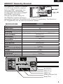
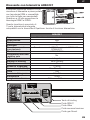
AR8020T Telemetry Receiver
The Spektrum™ AR8020T receiver
is a full range telemetry receiver
featuring DSM® technology. It is
compatible with all Spektrum™
aircraft radios that support DSM2®
and DSMX® technology.
Perform the failsafe setup for
the AR8020T receiver through a
compatible Spektrum Transmitter with Forward Programming. The Spektrum
PC Programmer can be used for firmware updates.
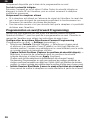
SPECIFICATIONS AR8020T
Type DSM2/DSMX 8 CH Telemetry Receiver
Application Air
Channels 8
Receivers 1
Remote Receiver
(not included)
SRXL2™ Remote Receiver Optional (SPM9747 or
SPM4651T)
Modulation DSM2/DSMX
Data Flight Log
Compatible No
Telemetry Integrated
Bind Method Bind Button
Failsafe Yes
Band 2.4GHz
Dimensions (LxWxH) 49 x 30 x 15mm
Weight 16g
Input Voltage 3.5–9V
Resolution 2048
Antenna Length 155mm and 186mm
Bind Button
Smart Port
XBUS Port
SRXL2 Port
Voltage Sensor Port

EN
4
AR8020T Receiver Installation
For optimum RF link performance, mount the antennas for optimal signal
reception accounting for all possible aircraft attitudes and positions. Orient the
antennas perpendicular to each other; typically vertical and horizontal and at
different angles.
Optional SRXL2 Remote Receiver (not included): If using an optional SRXL2
remote receiver, apply double-sided foam tape and mount it perpendicular to
and at least 2 inches away from the main receiver’s antenna.
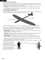
Airplanes with significant carbon fiber construction can create an RF shielding
effect, reducing range. The AR8020T is designed to overcome these critical RF
issues in carbon airplanes by outfitting the aircraft with two external antennas at
specific points that will ensure secure RF coverage from all angles of the aircraft.
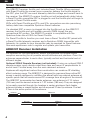
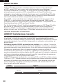
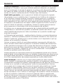
The AR8020T incorporates two feeder antennas; one antenna is 6.10 inches
(155 mm) and the second antenna is 7.32 inches (186 mm). They are designed
to be easily mounted through the fuselage in carbon airplanes. Each feeder
antenna includes acoaxial portion and an exposed 31mm tip antenna. The last
31mm is the active portion of the antenna.
186mm31mm
155mm31mm
Smart Throttle
The AR8020T receiver throttle port includes Smart Throttle. When equipped
with Smart Throttle the normal servo connector delivers the throttle signal to
the ESC, plus the ESC can send telemetry data like voltage and current back to
the receiver. The AR8020T receiver throttle port will automatically detect when
a Smart Throttle compatible ESC is plugged in and the throttle port will begin to
operate in Smart Throttle mode.
ESCs with Smart Throttle and IC3® and IC5® connectors can also pass along
battery data from compatible Spektrum Smart batteries.
If a standard ESC or servo is plugged into the throttle port on the AR8020T
receiver, the throttle port will operate normally (PWM signal) like any
conventional RC system. The AR8020T receiver is compatible with the
Spektrum Avian line of ESCs for Smart Throttle.
For Smart Throttle to function you must have a Smart Throttle ESC paired with
a Smart Throttle telemetry receiver, and a Spektrum DSMX transmitter with
telemetry. An update for your transmitter may be required for Smart features.
See www.spektrumrc.com to register and update your transmitter.

EN
5
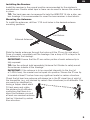
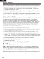
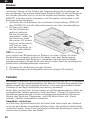
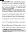
External Antennas
Full Carbon
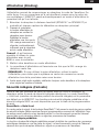
Installing the Receiver
Install the receiver in the normal position recommended by the airplane’s
manufacturer. Double-sided tape or foam can be used to secure the receiver
in place.
TIP: The hard case can be removed to help the AR8020T fit into a slim, car-
bon fuselage. It is recommended to cover the bare receiver in heat shrink.
Mounting the Antennas
To install the antennas, drill two 1/16-inch holes in the desired antenna
mounting positions.
Slide the feeder antennas through the holes until the 31mm tip, and about
2mm of coaxial, completely exit the fuselage. Use adrop of CA or tape to fix
the antenna to the fuselage.
IMPORTANT: Ensure that the 31mm active portion of each antenna tip is
fully exposed.
TIP: Use the optional (sold separately) Antenna Exit Guides to safely mount
the antennas outside of the fuselage.
IMPORTANT: If the antenna is to be mounted internally (in the front of
a2.4GHz fuse), the coaxial can be taped into position. Ensure the 31mm tip
is located at least 2 inches from any significant metal or carbon structure.
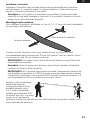
Check that at least one antenna will always be in the RF visual line of sight of
the transmitter (e.g. not blocked by carbon fiber structures) in all attitudes. This
can easily be visualized by
having a helper stand about
20 feet away and rotate
the airplane in all attitudes,
confirming that there is a
direct line between you and
at least one receiver antenna
that isn’t blocked by carbon
fiber structure.

EN
6
Using an AS3X SAFE receiver requires a Spektrum™ DSM2®/DSMX®
compatible transmitter with forward programming.
Transmitter and receiver binding
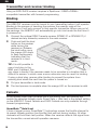
Binding
The AR8020T receiver must be bound to your transmitter before it will operate.
Binding is the process of teaching the receiver the specific code of the
transmitter so it will only connect to that specific transmitter. When new out of
the package, the AR8020T will automatically go into bind mode the first time it
is powered on.
1. Connect the optional SRXL2 remote receiver (SPM9747 or SPM4651T) if
desired and any telemetry sensors to the main receiver.
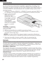
2. Push and hold the bind
button on the receiver
while turning the
receiver on. Release
the bind button once
the orange LED starts
to flash continuously,
indicating that the
receiver is in bind
mode.
TIP: It is still possible to
use a bind plug in the
BIND port if desired. This
can come in handy if the receiver needs to be mounted in a location that is
difficult to access, in which case a servo extension may be used for binding.
If using a bind plug, remove after binding to prevent the system from
entering bind mode the next time the power is turned on.
3. Put your transmitter in bind mode.
4. The bind process is complete when the orange LED on the receiver is solid.
Failsafe
In the unlikely event that the radio link is lost during use, the receiver will
enable the selected failsafe mode. Smart Safe + Hold Last is the default setting
on the AR8020T. Preset Failsafe and SAFE Failsafe are only available through
forward programming.
SmartSafe + Hold Last
If loss of signal occurs, SmartSafe™ technology moves the throttle channel to
its preset failsafe position (low throttle) that was set during binding. All other
channels will hold their last position. When the receiver detects the signal from
the transmitter, normal aircraft operation resumes.

EN
7
Forward Programming
Verify your transmitter is updated your transmitter to the latest Spektrum
AirWare™ software to take advantage of Forward Programming. See your
transmitter manual for updating instructions.
In your transmitter menu select Forward Programming -> Settings ->
• Select Failsafe -> Select each channel and assign it to Preset or Hold Last.
When you select a different channel for Output, a new group of settings appears.
Capture Failsafe Postions ->
Hold the control sticks in the desired failsafe positions and select Apply.
Channel selections must be individually set in Forward Programming to apply
the preset positions or each channel will default to Hold Last. The value
captured will be reflected in the position shown for each channel.
• Initiate Receiver Bind Mode
Gives you the option of putting the receiver into Bind Mode from this menu.
Preset Failsafe
With preset failsafe, you can set the specific control surface positions you want
to use if the signal is lost. When the receiver detects the signal from the trans-
mitter, normal aircraft operation resumes.
Only available through Forward Programming
Testing Failsafe
Secure the aircraft on the ground and remove the propeller. Test Failsafe
settings by turning the transmitter RF output off and noting how the receiver
drives the control surfaces.
Receiver Power Only
• If the receiver is turned when no transmitter signal is present, the throttle
channel will not have a control signal to avoid operating or arming the
electronic speed control.
• All other channels have no output until the receiver has linked to the
transmitter.

EN
8
Receiver Power System Requirements
Inadequate power systems that are unable to provide the necessary minimum
voltage to the receiver during flight have become the number one cause of
in-flight failures. Some of the power system components that affect the ability
to properly deliver adequate power include:
• Receiver battery pack (number of cells, capacity, cell type, state of charge)
• The ESC’s capability to deliver current to the receiver in electric aircraft
• The switch harness, battery leads, servo leads, regulators etc.
The AR8020T has a minimum operational voltage of 3.5 volts; it is highly
recommended the power system be tested per the guidelines below.
Recommended Power System Test Guidelines
If a questionable power system is being used (e.g. small or old battery,
ESC that may not have a BEC that will support high-current draw, etc.), it is
recommended that a voltmeter be used to perform the following tests.
View the receiver voltage during this test on your transmitters telemetry screen,
load the control surfaces (apply pressure with your hand) while monitoring the
voltage at the receiver. The voltage should remain above 4.8 volts even when
all servos are heavily loaded.
How QuickConnect™ Technology Works
• When the receiver voltage drops below 3.5 volts, the system ceases to
operate.
• When power is restored, the receiver immediately attempts to reconnect.
• If the transmitter was left on, the system reconnects typically in about
4/100 of a second.
QuickConnect is designed to allow you to fly safely through most short duration
power interruptions, however, the root cause of these interruptions must be
corrected before the next flight to prevent a crash.
NOTICE: If a brownout occurs in flight it is vital that the cause of the
brownout be determined and corrected.
IMPORTANT:
When using Y-harness or servo extensions with Spektrum
equipment, do not use reversing harnesses. Using reversing Y-harnesses or
servo extensions may cause servos to operate erratically or not function at all.

EN
9
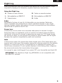
Flight Log
Flight Log data can help you optimize the control link for your aircraft. Flight
Log data is displayed on telemetry capable Spektrum transmitters.
Using the Flight Log
A - Fades on main receiver. B - Fades on remote receiver
L - Not available on AR8020T R - Not available on AR8020T
F - Frame losses H - Holds
Fades
Represents the loss of one bit of information on one receiver. Fades are
used to evaluate the performance of each individual receiver. If any single
receiver displays higher fade values it should be inspected and the antenna
repositioned to optimize the RF link.
Frame Loss
A frame loss occurs when one complete data packet is missed. A single
frame loss does not represent a loss of control, but frame losses should be
monitored. In the air it's normal to experience as many as 100 frame losses
per minute of flight. On the ground the number of frame losses will be higher
because the signal is hampered by earth and moisture.
Hold
A Hold occurs when 45 consecutive frame losses occur. This takes about one
second, and in this event the receiver moves the channel outputs to the failsafe
settings. If a hold ever occurs, it’s important to re-evaluate the system and
check every component. If your system displays a hold taking place, diagnose
the cause and resolve the issue before flying again.
It is normal to see a hold logged if you power OFF your transmitter and back ON.
IMPORTANT: The Spektrum Flight Log (SPM9540) is not compatible with
the AR8020T receiver.

EN
10
Range Testing
Before each flying session, and especially with a new model, it’s important to
perform a range check. All Spektrum aircraft transmitters incorporate a range
testing system, which reduces the output power to allow a range check.
1. With the model resting on the ground, stand approximately 100 feet (30
meters) away from the model.
2. Face the model with the transmitter in your normal flying position and put
your transmitter into range test mode.
3. You should have total control of the model in range test mode at 100 feet.
4. If control issues exist, call Horizon Product Support for further assistance.
Advanced Range Testing
The Standard Range Testing procedure is recommended for most sport aircraft.
For sophisticated aircraft that contain significant amounts of conductive
materials (e.g. turbine powered jets, scale aircraft with matalized finishes,
aircraft with carbon fuselages, etc.), the following advanced range check will
confirm that all receivers in the system are operating optimally as installed.
This advanced range check allows the RF performance of each receiver to
be evaluated independantly. A telemetry equipped Spektrum Transmitter is
required for the advanced range test.
1. Stand approximately 100 feet away from the model.
2. Face the model with the transmitter in your normal flying position and put
your transmitter into range test mode.
3. Have a helper position the model in various orientations (nose up, nose
down, nose toward the transmitter, nose away from the transmitter, etc.).
4. Observe the telemetry on your transmitter. Note any orientations that cause
higher fades or frame loss values. Perform this step for at least one minute.
5. Re-position any antennas related to higher fades as necessary.
6. Re-test to verify satisfactory results.
7. Repeat as neccesary.
After one minute, advanced testing should yield:
H - 0 holds
F - less than 10 frame losses
A, B - Fades will typically be less than 100. It’s important to compare the
relative frame losses. If a particular receiver has a significantly higher frame
loss value (2 to 3X) then the test should be redone. If the same results occur,
move the offending receiver to a different location.
TIP: Use the fade values for A to investigate the performance of the telemetry link.

EN
11
Optional Accesories
SPMA3065 USB Programming Cable
Telemetry Sensors and Accesories
SPMA9574 Aircraft Telemetry Airspeed Indicator
SPMA9587 Aircraft Telemetry GPS Sensor
SPMA9556 Air Telemetry Flight Pack Voltage Sensor: EC3/IC3
SPMA9604 Aircraft Telemetry Receiver Battery Energy Sensor
SPMA9605* Aircraft Telemetry Flight Pack Batt Energy Sensor
SPMA9551 12" Aircraft Telemetry Extension
SPMA9552 24" Aircraft Telemetry Extension
*For use with electric power system batteries that are separate from the
receiver battery(s).
Telemetry
The AR8020T features full range telemetry and will provide receiver battery
voltage, flight log data, and vario and altitude data without any additional
sensors. The altitude and vertical speed (variometer) sensor (
SPMA9589)
functions are already integrated in the SPMAR8020T.
Additional telemetry
devices such as voltage sensors can be connected to the volt port, and XBus
telemetry sensors can be connected through the XBus connector. Every XBus
telemetry device has two XBus ports, and XBus telemetry sensors can be
connected in a daisy chain in any order.
The AR8020T is not compatible with the Spektrum Temperature Sensor (SPMA9571)
See www.spektrumrc.com for more information about telemetry accesories

EN
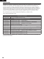
12
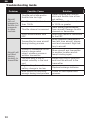
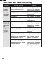
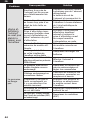
Problem Possible Cause Solution
Aircraft
will not
respond to
throttle but
responds
to other
controls
Throttle not at idle and/or
throttle trim too high
Reset controls with throttle
stick and throttle trim at low-
est setting
Throttle servo travel is lower
than 100%
Make sure throttle servo travel
is 100% or greater
Throttle channel is reversed
(With battery disconnected
from aircraft) Reverse throttle
channel on transmitter
Motor disconnected from
ESC
Make sure motor is connected
to the ESC
Aircraft will
not Bind
(during
binding) to
transmitter
Transmitter too near aircraft
during binding process
Move powered transmitter a
few feet from aircraft, discon-
nect and reconnect flight bat-
tery to aircraft
Aircraft or transmitter is too
close to large metal
object, wireless source or
another transmitter
Move aircraft and transmitter
to another location and at-
tempt binding again
The bind plug is not in-
stalled correctly in the bind
port
Install bind plug in bind port
and bind the aircraft to the
transmitter
Flight battery/transmitter
battery charge is too low Replace/recharge batteries
Bind button not held long
enough during bind process
Power off and repeat bind
process.
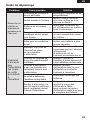
Troubleshooting Guide

EN
13
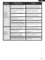
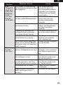
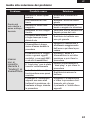
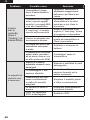
Problem Possible Cause Solution
Aircraft
will not
connect
(after
binding) to
transmitter
Transmitter too near aircraft
during connecting process
Move powered transmitter a few
feet from aircraft, disconnect and
reconnect flight battery to aircraft
Aircraft or transmitter is too
close to large metal object,
wireless source or another
transmitter
Move aircraft and transmitter
to another location and
attempt connecting again
Bind plug left installed in
bind port
Rebind transmitter to the
aircraft and remove the bind
plug before cycling power
Aircraft bound to different
model memory
(ModelMatchTM radios only)
Select correct model memory
on transmitter
Flight battery/Transmitter
battery charge is too low Replace/recharge batteries
Transmitter may have been
bound to a different aircraft
using different DSM protocol
Bind aircraft to transmitter
Control
surface
does not
move
Control surface, control horn,
linkage or servo damage
Replace or repair damaged
parts and adjust controls
Wire damaged or
connections loose
Do a check of wires and con-
nections, connect or replace
as needed
Transmitter is not bound
correctly or the incorrect
airplanes was selected
Re-bind or select correct air-
planes in transmitter
Flight battery charge is low Fully recharge flight battery
BEC (Battery Elimination Cir-
cuit) of the ESC is damaged Replace ESC

EN
14
1-Year Limited Warranty
What this Warranty Covers—Horizon Hobby, LLC, (Horizon) warrants to the original
purchaser that the product purchased (the “Product”) will be free from defects in
materials and workmanship for a period of 1 year from the date of purchase.
What is Not Covered—This warranty is not transferable and does not cover (i)
cosmetic damage, (ii) damage due to acts of God, accident, misuse, abuse, negligence,
commercial use, or due to improper use, installation, operation or maintenance, (iii)
modification of or to any part of the Product, (iv) attempted service by anyone other
than a Horizon Hobby authorized service center, (v) Product not purchased from
an authorized Horizon dealer, (vi) Product not compliant with applicable technical
regulations, or (vii) use that violates any applicable laws, rules, or regulations.
OTHER THAN THE EXPRESS WARRANTY ABOVE, HORIZON MAKES NO OTHER
WARRANTY OR REPRESENTATION, AND HEREBY DISCLAIMS ANY AND ALL IMPLIED
WARRANTIES, INCLUDING, WITHOUT LIMITATION, THE IMPLIED WARRANTIES
OF NON-INFRINGEMENT, MERCHANTABILITY AND FITNESS FOR A PARTICULAR
PURPOSE. THE PURCHASER ACKNOWLEDGES THAT THEY ALONE HAVE
DETERMINED THAT THE PRODUCT WILL SUITABLY MEET THE REQUIREMENTS OF
THE PURCHASER’S INTENDED USE.
Purchaser’s Remedy—Horizon’s sole obligation and purchaser’s sole and
exclusive remedy shall be that Horizon will, at its option, either (i) service, or (ii)
replace, any Product determined by Horizon to be defective. Horizon reserves
the right to inspect any and all Product(s) involved in a warranty claim. Service or
replacement decisions are at the sole discretion of Horizon. Proof of purchase is
required for all warranty claims. SERVICE OR REPLACEMENT AS PROVIDED UNDER
THIS WARRANTY IS THE PURCHASER’S SOLE AND EXCLUSIVE REMEDY.
Limitation of Liability—HORIZON SHALL NOT BE LIABLE FOR SPECIAL, INDIRECT,
INCIDENTAL OR CONSEQUENTIAL DAMAGES, LOSS OF PROFITS OR PRODUCTION OR
COMMERCIAL LOSS IN ANY WAY, REGARDLESS OF WHETHER SUCH CLAIM IS BASED
IN CONTRACT, WARRANTY, TORT, NEGLIGENCE, STRICT LIABILITY OR ANY OTHER
THEORY OF LIABILITY, EVEN IF HORIZON HAS BEEN ADVISED OF THE POSSIBILITY OF
SUCH DAMAGES. Further, in no event shall the liability of Horizon exceed the individual
price of the Product on which liability is asserted. As Horizon has no control over
use, setup, final assembly, modification or misuse, no liability shall be assumed nor
accepted for any resulting damage or injury. By the act of use, setup or assembly, the
user accepts all resulting liability. If you as the purchaser or user are not prepared to
accept the liability associated with the use of the Product, purchaser is advised to return
the Product immediately in new and unused condition to the place of purchase.
Law—These terms are governed by Illinois law (without regard to conflict of law
principals). This warranty gives you specific legal rights, and you may also have other
rights which vary from state to state. Horizon reserves the right to change or modify
this warranty at any time without notice.
WARRANTY SERVICES
Questions, Assistance, and Services—Your local hobby store and/or place of
purchase cannot provide warranty support or service. Once assembly, setup or use
of the Product has been started, you must contact your local distributor or Horizon
directly. This will enable Horizon to better answer your questions and service you in
the event that you may need any assistance. For questions or assistance, please

EN
15
visit our website at www.horizonhobby.com, submit a Product Support Inquiry, or
call the toll free telephone number referenced in the Warranty and Service Contact
Information section to speak with a Product Support representative.
Inspection or Services—If this Product needs to be inspected or serviced and
is compliant in the country you live and use the Product in, please use the Horizon
Online Service Request submission process found on our website or call Horizon to
obtain a Return Merchandise Authorization (RMA) number. Pack the Product securely
using a shipping carton. Please note that original boxes may be included, but are not
designed to withstand the rigors of shipping without additional protection. Ship via a
carrier that provides tracking and insurance for lost or damaged parcels, as Horizon
is not responsible for merchandise until it arrives and is accepted at our facility.
An Online Service Request is available at http://www.horizonhobby.com/content/
service-center_render-service-center. If you do not have internet access, please
contact Horizon Product Support to obtain a RMA number along with instructions
for submitting your product for service. When calling Horizon, you will be asked to
provide your complete name, street address, email address and phone number
where you can be reached during business hours. When sending product into
Horizon, please include your RMA number, a list of the included items, and a brief
summary of the problem. A copy of your original sales receipt must be included for
warranty consideration. Be sure your name, address, and RMA number are clearly
written on the outside of the shipping carton.
NOTICE: Do not ship LiPo batteries to Horizon. If you have any issue
with a LiPo battery, please contact the appropriate Horizon Product
Support ofce.
Warranty Requirements—For Warranty consideration, you must include your
original sales receipt verifying the proof-of-purchase date. Provided warranty
conditions have been met, your Product will be serviced or replaced free of charge.
Service or replacement decisions are at the sole discretion of Horizon.
Non-Warranty Service—Should your service not be covered by warranty, service
will be completed and payment will be required without notification or estimate of the
expense unless the expense exceeds 50% of the retail purchase cost. By submitting
the item for service you are agreeing to payment of the service without notification.
Service estimates are available upon request. You must include this request with your
item submitted for service. Non-warranty service estimates will be billed a minimum
of ½ hour of labor. In addition you will be billed for return freight. Horizon accepts
money orders and cashier’s checks, as well as Visa, MasterCard, American Express,
and Discover cards. By submitting any item to Horizon for service, you are agreeing to
Horizon’s Terms and Conditions found on our website http://www.horizonhobby.com/
content/service-center_render-service-center.
ATTENTION: Horizon service is limited to Product compliant in the
country of use and ownership. If received, a non-compliant Product
will not be serviced. Further, the sender will be responsible for
arranging return shipment of the un-serviced Product, through a
carrier of the sender’s choice and at the sender’s expense. Horizon
will hold non-compliant Product for a period of 60 days from
notication, after which it will be discarded.
10/2015

EN
16
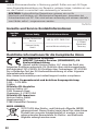
Warranty and Service Contact Information
FCC Information
FCC ID: BRWSPMAR8020T
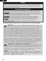
Supplier’s Declaration of Conformity
Spektrum AR8020T Telemetry Receiver (SPMAR8020T)
This device complies with part 15 of the FCC Rules. Operation is
subject to the following two conditions: (1) This device may not cause
harmful interference, and (2) this device must accept any interference
received, including interference that may cause undesired operation.
CAUTION: Changes or modifications not expressly approved by the
party responsible for compliance could void the user’s authority to
operate the equipment.
NOTE: This equipment has been tested and found to comply with the limits
for a Class B digital device, pursuant to part 15 of the FCC Rules. These limits
are designed to provide reasonable protection against harmful interference
in a residential installation. This equipment generates, uses and can radiate
radio frequency energy and, if not installed and used in accordance with
the instructions, may cause harmful interference to radio communications.
However, there is no guarantee that interference will not occur in a particular
installation. If this equipment does cause harmful interference to radio or
television reception, which can be determined by turning the equipment off
and on, the user is encouraged to try to correct the interference by one or
more of the following measures:
• Reorient or relocate the receiving antenna.
• Increase the separation between the equipment and receiver.
• Connect the equipment into an outlet on a circuit different from that to
which the receiver is connected.
• Consult the dealer or an experienced radio/TV technician for help.
Country of
Purchase Horizon Hobby Contact Information Address
United
States of
America
Horizon Service Center
(Repairs and Repair
Requests)
servicecenter.horizonhobby.
com/RequestForm/
2904 Research Rd
Champaign, Illinois,
61822 USA
Horizon Product
Support
(Product Technical
Assistance)
productsupport@
horizonhobby.com.
877-504-0233
Sales websales@horizonhobby.com
800-338-4639
EU
Horizon Technischer
Service service@horizonhobby.eu Hanskampring 9
D 22885
Barsbüttel,
Germany
Sales: Horizon Hobby
GmbH +49 (0) 4121 2655 100
requirements as determined by FCC regulations.
hands, wrists, ankles and feet) and the antenna to meet RF exposure safety
separation distance of at least 20 cm between your body (excluding fingers,
When operating your Spektrum receiver, please be sure to maintain a

EN
17
Compliance Information for the European Union
IC Information
CAN ICES-3 (B)/NMB-3(B)
IC: 6157A-SPMAR8020T
This device contains license-exempt transmitter(s)/receivers(s) that comply
with Innovation, Science, and Economic Development Canada’s license-
exempt RSS(s). Operation is subject to the following 2 conditions:
1. This device may not cause interference.
2. This device must accept any interference, including interference that
may cause undesired operation of the device.
EU Compliance Statement:
AR8020T Telemetry Receiver (SPMAR8020T); Hereby,
Horizon Hobby, LLC declares that the device is in compliance
with the following: EU Radio Equipment Directive 2014/53/EU.
The full text of the EU declaration of conformity is available at the following
internet address: https://www.horizonhobby.com/content/support-render-
compliance.
Wireless Frequency Range and Wireless Output Power:
2404 – 2476 MHz
20dBm
EU Manufacturer of Record:
Horizon Hobby, LLC
2904 Research Road
Champaign, IL 61822 USA
EU Importer of Record:
Horizon Hobby, GmbH
Hanskampring 9
22885 Barsbüttel Germany
WEEE NOTICE:
This appliance is labeled in accordance with European
Directive 2012/19/EU concerning waste of electrical and
electronic equipment (WEEE). This label indicates that this
product should not be disposed of with household waste. It
should be deposited at an appropriate facility to enable
recovery and recycling.
de distance entre la source de rayonnement et votre corps.
unenvironnement non contrô lé. Ceté quipementdoitê treinstallé etutilisé avec un minimum de 20cm
Ceté quipementestconforme aux limitesd'exposition aux rayonnements IC é tablies pour
Dé clarationd'exposition aux radiations:
Web: HorizonHobby.com
Email: compliance@horizonhobby.com
Champaign, IL 61822
2904 Research Rd.,
Horizon Hobby, LLC

DE
18
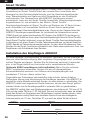
Die folgenden Begriffe werden in der gesamten Produktliteratur verwendet, um auf
unterschiedlich hohe Gefahrenrisiken beim Betrieb dieses Produkts hinzuweisen:
WARNUNG: Wenn diese Verfahren nicht korrekt befolgt werden, ergeben sich
wahrscheinlich Sachschäden, Kollateralschäden und schwere Verletzungen ODER
mit hoher Wahrscheinlichkeit oberflächliche Verletzungen.
ACHTUNG: Wenn diese Verfahren nicht korrekt befolgt werden, ergeben sich
wahrscheinlich Sachschäden UND die Gefahr von schweren Verletzungen.
HINWEIS: Wenn diese Verfahren nicht korrekt befolgt werden, können sich
möglicherweise Sachschäden UND eine geringe oder keine Gefahr von
Verletzungen ergeben.
HINWEIS
Allen Anweisungen, Garantien und anderen zugehörigen Dokumenten sind Ände-
rungen nach Ermessen von Horizon Hobby, LLC vorbehalten. Aktuelle Produktlite-
ratur fi nden Sie unter www.horizonhobby.com oder www.towerhobbies.com im
Support-Abschnitt für das Produkt.
Nicht geeignet für Kinder unter 14 Jahren. Dies ist kein Spielzeug.
WARNUNG: Lesen Sie die GESAMTE Bedienungsanleitung durch, um
sich vor der Inbetriebnahme mit den Funktionen des Produkts vertraut zu
machen. Wird dieses Produkt nicht korrekt betrieben, kann dies zu Schäden am
Produkt oder anderen Sachschäden und zu schweren Verletzungen führen.
Dies ist ein hochentwickeltes Hobbyprodukt und KEIN Spielzeug. Es muss mit
Vorsicht und gesundem Menschenverstand betrieben werden und erfordert ge-
wisse technische Grundfähigkeiten. Wird dieses Produkt nicht auf eine sichere
und verantwortungsvolle Weise betrieben, kann dies zu Verletzungen oder Schä-
den am Produkt oder anderen Sachwerten führen. Dieses Produkt eignet sich
nicht für die Verwendung durch Kinder ohne direkte Überwachung eines Erwach-
senen. Versuchen Sie nicht ohne Genehmigung durch Horizon Hobby, LLC, das
Produkt zu zerlegen, es mit inkompatiblen Komponenten zu verwenden oder auf
jegliche Weise zu erweitern. Diese Bedienungsanleitung enthält Anweisungen für
Sicherheit, Betrieb und Wartung. Es ist unbedingt notwendig, vor Zusammenbau,
Einrichtung oder Verwendung alle Anweisungen und Warnhinweise im Handbuch
zu lesen und zu befolgen, damit das Produkt bestimmungsgemäß betrieben wer-
den kann und Schäden oder schwere Verletzungen vermieden werden.
WARNUNG ZU GEFÄLSCHTEN PRODUKTEN. Bitte kaufen Sie Ihre
Spektrum Produkte immer von einem autorisiertem Händler um sicher-
zu stellen, dass Sie ein authentisches hochqualitatives original Spektrum Pro-
dukt gekauft haben. Horizon Hobby lehnt jede Unterstützung, Service oder Ga-
rantieleistung von gefälschten Produkten oder Produkten ab die von sich in
Anspruch nehmen kompatibel mit Spektrum oder DSM zu sein.
HINWEIS: Dieses Produkt ist ausschließlich für die Verwendung in
unbemanten, ferngesteuerten Fahrzeugen und Fluggeräten im Hobbybereich
vorgese-hen. Horizon Hobby lehnt jede Haftung und Garantieleistung au-
sserhalb der vorgesehen Verwendung ab.
ERKLÄRUNG DER BEGRIFFE

DE
19
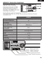
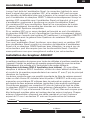
AR8020T Telemetrie Empfänger
Der Empfänger Spektrum
AR8020T ist ein kompletter
Telemetrieempfänger mit DSM-
Technologie und er ist mit allen
Spektrum- Bordfunkgeräten
kompatibel, die DSM2- und DSMX-
Technologie unterstützen.
Der Empfänger umfasst 2 integrierte
Telemetrieanschlüsse, die mit den telemetriefähigen Spektrum-Sendern
kompatibel sind.
AR8020T
Abmessungen DSM2/DSMX Telemetrieempfänger mit 8 Kanälen
Anwendungsbereich Air
Gewicht 8
Empfänger 1
Funkempfänger
(nicht enthalten)
SRXL2 Funkempfänger, optional (SPM9747 oder
SPM4651T)
Modulation DSM2/DSMX
Daten Flight-Log
kompatibel Nein
Telemetrie Integriert
Bindungsmethode Bindungsschalter
Failsafe Ja
Band 2.4GHz
Antennenlänge (LxWxH) 49 x 30 x 15mm
Gewicht 16g
Eingangsspannung 3.5–9V
Auflösung 2048
Antennenlänge 155mm und 186mm
XBUS-Anschluss
Bindungsschalter
SRXL2-Anschluss
Spannungssensoranschluss
Smart Throttle-Anschluss

DE
20
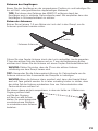
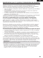
Installation des Empfängers AR8020T
Um eine optimale Funkverbindung zu erreichen, montieren Sie die Antennen so,
dass sie unter Berücksichtigung aller möglichen Flugzeuglagen und -positionen
optimal Signale empfangen. Richten Sie die Antennen senkrecht zueinander
aus; in der Regel vertikal und horizontal und in verschiedenen Winkeln.
Optionale SRXL2 empfängers (nicht enthalten): Wenn Sie die optionale
SRXL2 empfängers verwenden, bringen Sie sie mit doppelseitigem
Schaumklebeband senkrecht zur Antenne des Hauptempfängers und
mindestens 2 Zoll von dieser entfernt an.
Flugmodelle aus Carbonfaser Verbundstoffen oder mit sehr hohem Anteil an
Carbonfaser können eine Abschirmung der Empfänger bewirken. Der AR8020T ist
speziell für solche Modelle entwickelt worden um eben dieses zu unterbinden. Der
AR8020T besitzt zwei sogenannte Feeder Antennen, die aus dem Rumpf geführt
werden können um die Empfangsqualität in optimaler Güte zu gewährleisten.
Der AR8020T verfügt über zwei Zuleitungsantennen; eine Antenne ist 155 mm (6,10
Zoll) und die zweite 186 mm (7,32 Zoll) groß. Sie sind so konstruiert, dass sie einfach
durch den Rumpf von Flugzeugen aus Carbonfasern montiert werden können. Jede
Zuleitungsantenne verfügt über einen koaxialen Abschnitt und eine freiliegende
Antennenspitze von 31mm. Die letzten 31mm sind der aktive Teil der Antenne.
186mm31mm
155mm31mm
SmartThrottle
Der Gasanschluss des Empfängers AR8020T bietet Smart Throttle. Bei der
Ausstattung mit Smart Throttle liefert der normale Servo-Anschluss das
Gassignal an den Geschwindigkeitsregler, und der Geschwindigkeitsregler
kann Telemetriedaten wie Spannung und Stromstärke an den Empfänger
zurücksenden. Der Gasanschluss des AR8020T-Empfängers erkennt
automatisch, wenn ein mit Smart Throttle kompatibler Geschwindigkeitsregler
angeschlossen ist, und schaltet in den Modus „Smart Throttle“.
Geschwindigkeitsregler mit Smart Throttle und Steckern der IC-Serie können
auch Akkudaten von kompatiblen Spektrum Smart-Akkus weitergeben.
Wird ein Standard-Geschwindigkeitsregler oder -Servo an den Gasanschluss des
AR8020T-Empfänger
angeschlossen, so funktioniert der Gasanschluss normal
(PWM-Signal) wie jedes herkömmliche RC-System.
Der
AR8020T-Empfänger
ist
kompatibel mit Spektrum Avian, einer Geschwindigkeitsregler-Serie für Smart Throttle.
Damit Smart Throttle funktioniert, muss ein Smart-Throttle-Geschwindigkeitsregler
in Verbindung mit einem Smart-Throttle-Telemetrieempfänger und einen Spektrum
DSMX-Sender mit Telemetrie verwendet werden. Es kann eine Aktualisierung Ihres
Senders für die Smart-Funktionen erforderlich sein. Siehe www.spektrumrc.com zum
Registrieren und Aktualisieren Ihres Senders.
La page est en cours de chargement...
La page est en cours de chargement...
La page est en cours de chargement...
La page est en cours de chargement...
La page est en cours de chargement...
La page est en cours de chargement...
La page est en cours de chargement...
La page est en cours de chargement...
La page est en cours de chargement...
La page est en cours de chargement...
La page est en cours de chargement...
La page est en cours de chargement...
La page est en cours de chargement...
La page est en cours de chargement...
La page est en cours de chargement...
La page est en cours de chargement...
La page est en cours de chargement...
La page est en cours de chargement...
La page est en cours de chargement...
La page est en cours de chargement...
La page est en cours de chargement...
La page est en cours de chargement...
La page est en cours de chargement...
La page est en cours de chargement...
La page est en cours de chargement...
La page est en cours de chargement...
La page est en cours de chargement...
La page est en cours de chargement...
La page est en cours de chargement...
La page est en cours de chargement...
La page est en cours de chargement...
La page est en cours de chargement...
La page est en cours de chargement...
La page est en cours de chargement...
La page est en cours de chargement...
La page est en cours de chargement...
La page est en cours de chargement...
La page est en cours de chargement...
La page est en cours de chargement...
La page est en cours de chargement...
La page est en cours de chargement...
La page est en cours de chargement...
-
 1
1
-
 2
2
-
 3
3
-
 4
4
-
 5
5
-
 6
6
-
 7
7
-
 8
8
-
 9
9
-
 10
10
-
 11
11
-
 12
12
-
 13
13
-
 14
14
-
 15
15
-
 16
16
-
 17
17
-
 18
18
-
 19
19
-
 20
20
-
 21
21
-
 22
22
-
 23
23
-
 24
24
-
 25
25
-
 26
26
-
 27
27
-
 28
28
-
 29
29
-
 30
30
-
 31
31
-
 32
32
-
 33
33
-
 34
34
-
 35
35
-
 36
36
-
 37
37
-
 38
38
-
 39
39
-
 40
40
-
 41
41
-
 42
42
-
 43
43
-
 44
44
-
 45
45
-
 46
46
-
 47
47
-
 48
48
-
 49
49
-
 50
50
-
 51
51
-
 52
52
-
 53
53
-
 54
54
-
 55
55
-
 56
56
-
 57
57
-
 58
58
-
 59
59
-
 60
60
-
 61
61
-
 62
62


dans d''autres langues
- italiano: Spektrum AR8020T Guida utente
- English: Spektrum AR8020T User guide
- Deutsch: Spektrum AR8020T Benutzerhandbuch
Documents connexes
-
Spektrum AR10100T Mode d'emploi
-
Spektrum AR7010 7-Channel DSMX Receiver Mode d'emploi
-
-
Spektrum AR6210 6-Channel DSMX Receiver Le manuel du propriétaire
-
-
-
-
-
-