Master TB117 Le manuel du propriétaire
- Catégorie
- Congélateurs
- Taper
- Le manuel du propriétaire
Ce manuel convient également à

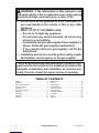
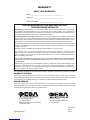
IMPORTANT: Read and understand this manual before
assembling, starting or servicing heater. Improper use
of heater can cause serious injury. Keep this manual for
future reference.
GENERAL HAZARD WARNING:
Failure to comply with the precautions and instructions
provided with this heater, can result in death, serious
bodily injury and property loss or damage from hazards
of re, explosion, burn, asphyxiation, carbon monoxide
poisoning and/or electrical shock.
Only persons who can understand and follow the instruc-
tions should use or service this heater.
If you need assistance or heater information such as an in-
structions manual, labels, etc. contact the manufacturer.
Save this manual for future reference.
For more information, visit www.desatech.com
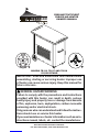
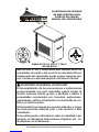
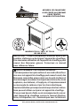
PROPANE TENT EVENT
FORCED AIR HEATER
OWNER’S MANUAL
MODELS TB116, TB117 AND TB118
125,000 BTU/HR
125
TENT
Event
by

www.desatech.com 120193-01A2
WARNING: If the information in this manual is not
followed exactly, a re or explosion may result causing
property damage, personal injury or loss of life.
— Do not store or use gasoline or other ammable va-
pors and liquids in the vicinity of this or any other
appliance.
— WHAT TO DO IF YOU SMELL GAS
• Do not try to light any appliance.
• Do not touch any electrical switch; do not use any
phone in your building.
• Immediately call your gas supplier from a neighbor’s
phone. Follow the gas supplier’s instructions.
• If you cannot reach your gas supplier, call the re
department.
— Installation and service must be performed by a quali-
ed installer, service agency or the gas supplier.
This is an unvented gas red tent heater. It uses air (oxy-
gen) from the tent in which it is installed. Provisions for
adequate combustion and ventilation air must be pro-
vided. Provide at least 42 square inches of opening.
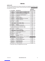
TABLE OF CONTENTS
Safety .................................................................. 3
Ventilation ............................................................ 5
Product Identication ........................................... 6
Propane Supply ................................................... 6
Unpacking............................................................ 7
Theory of Operation............................................. 7
Assembly ............................................................. 8
Installation ......................................................... 10
Operation ............................................................11
Storage .............................................................. 12
Maintenance ...................................................... 12
Service............................................................... 12
Specications .................................................... 16
Troubleshooting ................................................. 17
Technical Service............................................... 18
Wiring Diagram .................................................. 19
Replacement Parts ............................................ 21
Accessory .......................................................... 21
Parts .................................................................. 22
Warranty ............................................................ 28

www.desatech.com
120193-01A 3
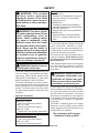
SAFETY
General
ANSI/NFPA 102
Standard for Grandstands, Folding and
telescopic Seating, Tents and Mem-
brane Structures
ANSI/NFPA 58
Standard for Storage and Handling of
Liquieed Petroleum Gas Latest Edition
ANSI Z223.1/NFPA 54
National Fuel Gas Code Latest Edition
ANSI/NFPA 70
National Electric Code Latest Edition
CSA C22.1 Canadian Electrical Code
Part 1
The primary purpose of construction heaters
is to provide temporary heating of buildings
under construction, alteration or repair.
Properly used, the heater provides safe eco-
nomical heating. Products of combustion are
vented into the area being heated.
We cannot foresee every use which may be
made of our heaters. Check with your local
re safety authority if you have questions
about heater use.
Other standards govern the use of fuel gases
and heat producing products for specific
uses. Your local authorities can advise you
about these.
WARNING: When used with-
out adequate combustion and
ventilation air, heater may give
off excessive carbon monoxide,
an odorless, poisonous gas.
Do not install heater until all necessary provi-
sions are made for combustion and ventilation
air. Consult the written instructions provided
with the heater for information concerning
combustion and ventilation air. In the absence
of instructions, refer to the national fuel gas
code, ANS Z223.1, Section 5.3 or applicable
local codes.
This heater is equipped with a an Oxygen
Depletion Sensing (ODS) safety shutoff
system designed to turn off the heater if not
enough fresh air is available.
Do not tamper with oxygen
depletion safety system!
WARNING: This product
contains and/or generates
chemicals known to the State
of California to cause cancer or
birth defects or other reproduc-
tive harm.
WARNING: Fire, burn, inhala-
tion and explosion hazard. Keep
solid combustibles, such as
tables, chairs, building materi-
als, paper or cardboard, a safe
distance away from the heater
as recommended by the instruc-
tions. Never use the heater in
spaces which do or may contain
volatile or airborne combustibles
or products such as gasoline,
solvents, paint thinner, dust par-
ticles or unknown chemicals.
WARNING: Not for home or
recreational vehicle use.
The heater is designed and approved for use
as a tent heater in accordance with these
instructions. CHECK WITH YOUR LOCAL
FIRE SAFETY AUTHORITY IF YOU HAVE
QUESTIONS ABOUT APPLICATIONS.
The heater is designed for use as a construc-
tion heater and as a vent-free tent heater. The
heater is designed for use in the space being
heated. The heater uses the air from within
the space being heated for combustion and
ventilation.
Applicable Standards:
For USA applications
ANSI Z83.7 - 2000
Gas Fired Construction Heaters
CGA 2.14 - 2000
Gas Fired Construction Heaters
CSA 3.06 - 2006
Portable Gas Fired Unvented Tent Heaters
For Canadian applications
ANSI Z83.7 - 2000
Gas Fired Construction Heaters
CGA 2.14 - 2000
Gas Fired Construction Heaters

www.desatech.com 120193-01A4
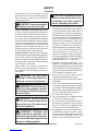
SAFETY
Continued
If heater shuts off, do not relight until you
provide fresh air. If heater keeps shutting off,
have it serviced. Keep burner and control
compartment clean.
DANGER: Carbon monoxide
poisoning may lead to death!
Carbon Monoxide Poisoning: Early signs
of carbon monoxide poisoning resemble the
u, with headaches, dizziness, and/or nausea.
If you have these signs, the heater may not
be working properly. Get fresh air at once!
Check for proper ventilation and have heater
serviced. Some people are more affected by
carbon monoxide than others. These include
pregnant women, people with heart or lung
disease or anemia, those under the inuence
of alcohol, and those at high altitudes.
Propane/LP Gas: Propane/LP gas is odorless.
An odor-making agent is added to propane/LP
gas. The odor helps you detect a propane/LP
gas leak. However, the odor added to Propane/
LP gas can fade. propane gas may be present
even though no odor exists.
Make certain you read and understand all
warnings. Keep this manual for reference. It
is your guide to safe and proper operation of
this heater.
WARNING: Do not place
clothing or other ammable ma-
terial on or near the appliance.
WARNING: Due to high tem-
peratures, the appliance should
be located out of trafc and away
from furniture.
WARNING: Young children
should be carefully supervised
when they are in the same room
with the appliance.
WARNING: Children and
adults should be alerted to the
hazard of high surface tempera-
ture and should stay away to avoid
burns or clothing ignition.
CAUTION: Any safety screen
or guard removed for servicing
an appliance must be replaced
prior to operating the heater.
1. Install and use heater with care. Follow all
local ordinances and codes. In the absence
of local ordinances and codes, refer to
the Standard for Storage and Handling of
Liqueed Petroleum Gas, ANSI/NFPA 58,
the Natural Gas and Propane Installation
Code, CSA B149.1, and ANSI/NFPA 102
Standard for Grandstands, Folding and
telescopic Seating, Tents and Membrane
Structures. This instructs on the safe stor-
age and handling of propane/LP gases.
2. Use only the electrical voltage and fre-
quency specied on model plate. The
electrical connections and grounding of
the heater shall follow the National Electric
Code, ANSI/NFPA 70 or the Canadian
Electrical Code, Part 1, CSA C22.1.
3. Electrical Grounding Instructions - This
appliance is equipped with a three-prong
(grounding) plug for your protection against
shock hazard and should be plugged di-
rectly into a properly grounded three-prong
GFI receptacle or extension cord.
4. Use only the hose and factory preset
regulator provided with the heater.
5. Use only propane/LP gas set up for vapor
withdrawal.
6.
This is an unvented gas-red tent heater.
It uses air (oxygen) from the tent in which
it is installed. Provide adequate ventilation.
Before using heater, provide at least a 42 in
2
(271 cm
2
) opening of fresh, outside air.
7. For indoor and outdoor use.
8. Do not use heater in occupied dwellings
or in living or sleeping quarters.
9. Do not use heater in basement or below
ground level. Propane/LP gas is heavier
than air. If a leak occurs, propane/LP gas
will sink to the lowest possible level.
10. Keep appliance area clear and free from
combustible materials, gasoline, paint
thinner, and other ammable vapors and
liquids. Dust is combustible. Do not use
heater in areas with high dust content.

www.desatech.com
120193-01A 5
29. The heater must be installed so that the
location of the heater does not obstruct or
interfere with normal or emergency exits
and doors or walkways in the structure.
VENTILATION
WARNING: Follow the mini-
mum fresh, outside air ventila-
tion requirements. If proper
fresh, outside air ventilation is
not provided, carbon monoxide
poisoning can occur. Provide
proper fresh, outside air ventila-
tion before running heater.
Provide a fresh air opening of at least 42 in2
(271 cm2) opening of fresh, outside air.
Example: 3" high x 14" long = 42 in2. Provide
extra fresh air if more heaters are being used.
Determining Correct Heater Size
1. Determine volume of space to heat:
Length x Width x Height
50 feet x 30 feet x 15 feet = 22,500 ft3
2. Determine desired temperature rise:
Desired temperature 65° - 25° outside
temperature = 40° rise
3.
Multiply volume x rise: 22,500 x 40 = 900,000
4.
To determine how many BTU’s are needed
multiply by 0.133
900,000 x 0.133 = 119,000 Btu
The heater thermostat will cycle on and off to
maintain the desired room temperature more
often if the BTU/hr is oversized for the space
being heated. The air inltration and leakage
of heated air through cracks, passageway
openings, etc., will adjust the required BTU’s
needed for the desired temperature.
Ventilation Air Requirements - National
Fuel Gas Code ANSI Z223.1/NFPA 54
1 inch2 of opening per 3,000 BTU with
outside air
1 inch2 of opening per 1,000 BTU with non-
outside air
Determine fresh air needed
Input Max. divided by 3,000
125,000 BTU/hr ÷ 3,000 = 41.66
Provide 42 inch
2
of opening to fresh, outside air
3" high x 14" long - 42 inches2
11. Minimum heater clearances from com-
bustible materials: Outlet: 8 ft. (2.40 m),
Sides: 1 ft. (30 cm), Top: 3 ft. (0.91 m),
Rear: 1 ft. (30 cm)
12. Keep heater at least 6 ft. (1.83 m) from
propane/LP tank(s). Do not point heater
at propane/LP tank(s) within 20 ft. (6 m).
In Canada keep heater at least 10 ft. (3
m) from propane/LP tank(s).
13. Keep propane/LP tank(s) below 100° F
(38˚ C).
14. The minimum surrounding air temperature
rating for this heater is -20º F (-29º C).
15. Check heater for damage before each
use. Do not use a damaged heater.
16. Check hose before each use of heater.
If highly worn or cut, replace with hose
specied by manufacturer before using
heater.
17. Locate heater on stable and level surface
if heater is hot or operating.
18. Never block air inlet (rear) or air outlet
(front) of heater.
19. Keep heater away from strong drafts, wind,
water spray, rain, or dripping water.
20. Keep children and animals away from
heater.
21. Never move, handle, or service a hot
or operating heater. Severe burns may
result. You must wait 15 minutes after
turning heater off.
22. To prevent injury, wear gloves when han-
dling heater.
23. Never attach duct work to heater.
24. Space heaters used in the vicinity of
tarpaulins, canvas or similar enclosure
materials shall be located a safe distance
from such materials. These enclosure
materials shall be of a re retardant na-
ture. These enclosure materials shall be
securely fastened to prevent them from
igniting or from upsetting the space heater
due to wind action.
25. Do not alter heater. Keep heater in its
original state.
26. Do not use heater if altered.
27. Turn off propane/LP supply to heater and
unplug when not in use.
28. Use only original replacement parts. This
heater must use design-specic parts.
Do not substitute or use generic parts.
Improper replacement parts could cause
serious or fatal injuries.
SAFETY
Continued

www.desatech.com 120193-01A6
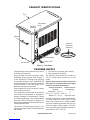
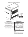
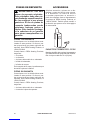
Figure 1 - Tent Heater
Top
Power Cord
Hose and
Regulator
Assembly
Gas Inlet
Handle
Thermostat
Knob
ON/OFF
Switches
Receptacle
PROPANE SUPPLY
PRODUCT IDENTIFICATION
1. The amount of propane gas in tank(s)
2. The temperature of tank(s)
The following chart shows the number of
100 lb. (45 kg) tanks needed to run this
heater.
Smaller tanks can be used for limited run
times but it is recommended to use larger
tanks for optimum performance.
Average Temperature Number Of Tanks
At Tank (100 lb/45 kg)
Above 20° F (-6.7° C) 2
20° F (-6.7° C) to 0° F (-18° C) 3
Below 0° F (-18° C) Use larger tank
Less gas is vaporized at lower temperatures.
You may need two or more 100 lb. (45 kg)
tanks or one larger tank in colder weather.
Your local propane gas dealer will help you
select the proper supply system. The mini-
mum surrounding air temperature rating for
each heater is -20° F (-29° C).
Propane/LP gas and propane tank(s) are to
be furnished by the user.
Use this heater only with a propane vapor
withdrawal supply system. See Chapter 5
of the Standard for Storage and Handling
of Liqueed Petroleum Gas, ANSI/NFPA 58
and the Natural Gas and Propane Installation
Code CSA B149.1. Your local library or re
department will have this booklet.
Keep propane/LP tank(s) at least 5 ft away
from the side of the tent.
The propane/LP tank(s) shall be protected
from vehicles and secured in accordance
with the Standard for Grandstands, Folding
and Telescopic Seating, Tents and Membrane
Structures NFPA 102 and the Standard for
Storage and Handling of Liquieed Petroleum
Gases ANSI/NFPA 58.
The amount of propane gas ready for use
from propane tanks varies. Two factors decide
this amount:

www.desatech.com
120193-01A 7
UNPACKING
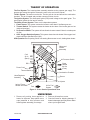
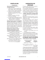
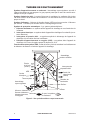
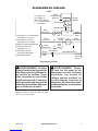
Figure 2 - Cross Section Operational View
Clean
Heated
Air Out
(Front)
Combustion Chamber
Hose/Regulator
Assembly
Injector
Motor and
Blower
Assembly
Cool
Air In
(Back)
Power Cord
Fuel
DSI
Air for Fuel
System
Thermal Switch
Ignitor, Flame
Sensor and ODS
Burner
Air Pressure Switch
1. Remove all packing items applied to
heater for shipment. Keep plastic cover
caps (attached to inlet connector and
hose/regulator assembly) for storage.
2. Remove all items from carton.
3. Check all items for shipping damage. If
heater is damaged, promptly inform dealer
where you bought heater.
THEORY OF OPERATION
The Fuel System: The hose/regulator assembly attaches to the propane gas supply. The
propane gas moves through the automatic control valve and out the injector.
The Air System: The motor turns the fan. The fan pulls air into and around the combustion
chamber. This air is heated and provides a stream of clean, hot air.
The Ignition System: The direct spark ignitor (DSI) sends voltage to the spark ignitor. The
spark ignitor ignites the fuel and air mixture.
The Safety Control System: There are 4 independent systems:
1. Flame Sensor: This system causes the heater to shut down if the ame goes out.
2. Thermal Switch: This system causes the heater to shut down if the heater gets too hot
(blocked openings).
3. Air Pressure Switch: The system will not allow the heater to start if there is not adequate
air ow.
4. ODS - Oxygen Depletion System: This system shuts down the heater if the oxygen level
drops below the specied level (18%).
ODS Operation: Burner porting "blows" out causing ame sensor to cool, shutting down heater.

www.desatech.com 120193-01A8
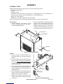
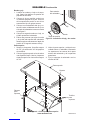
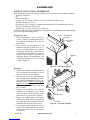
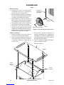
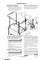
ASSEMBLY
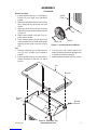
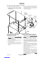
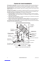
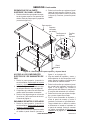
Figure 3 - Attaching Handles
Handle
Screw
Nut Lock Washer
Figure 4 - Installing Casters
Nut
Flat Washer
Caster
ASSEMBLY ITEMS
Before assembling heater, make sure you have the items listen below.
• Phillips head screwdriver
• Wrench
• Hardware packet
Handles (2), 3/4" Screws (4), 1/4-20 Nuts (4), 1/4 Flat washers (4), 1/4 Lock washers (4)
Casters (2), 3/8" Nut (2), 3/8 Lock washers (2), 3/8 Flat Washers (4)
Wheels (2), Push Caps (2)
Brackets (4), 1/2" black screws (8), 3/8" screws (8)
Note: Place metal parts on packaging during assembly to protect from scratches.
Casters
1. Remove casters, 3/8 at washers, 3/8
lock washers and 3/8 nuts from hardware
packet.
2. You may wish to remove side panel from
heater to make installing casters easier.
If so, see Top and Side Panel Removal
on page 13. Figure 4 shows side panel
removed for clarity.
3. Use a spacer to prop end of heater up
so holes in base can be accessed (the 2
wheels stacked on top of each other will
accomplish this).
4. Place a at washer onto threaded stem of
caster. Insert caster stem through hole in
cabinet base as shown in Figure 4.
5. Attach each caster to base with a at
washer, a lock washer and a nut as shown
in Figure 4.
Side Handles
1. Remove handles, 3/4" screws, 1/4-20
nuts, 1/4 at washers and 1/4 lock wash-
ers from hardware packet.
2. Attach each handle to side panels with 2
screws, 2 nuts, 2 at washers and 2 lock
washers. Insert screw from outside of
heater and through handle. From inside
of heater, attach a at washer, then a lock
washer then a nut as shown in Figure 3.
Flat Washer
Lock Washer

www.desatech.com
120193-01A 9
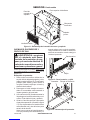
Bracket
Top
Bracket
Screws
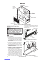
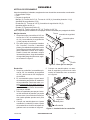
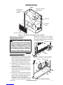
Figure 6 - Attaching Top
ASSEMBLY
Continued
Figure 5 - Installing Axle and Wheels
Heater
Front
Axle
Wheel
Push Cap
Wheels and Axle
1. Locate wheels and axle in packaging.
Remove 2 push caps from hardware
packet.
2. Stand axle upright placing one end on the
oor. Gently tap one push cap onto end
of axle.
3. Slide one wheel onto axle then carefully
slide axle through heater body as shown
in Figure 5.
4. Slide second wheel onto axle from op-
posite side of heater.
5. Have another person secure wheel and
axle from other side of heater while gently
tapping second push cap onto end of
axle.
Top
1. Remove 4 brackets, (8) 1/2" black screws
and (8) 3/8" screws from hardware
packet.
2. Lay top upside down on a clean surface.
Attach 4 brackets to top with 1/2" black
screws.
3. Turn top over and carefully place over
heater, positioning brackets through slots
in heater front and rear panels.
4.
Attach brackets to heater with 3/8" screws.
Bracket
Slots

www.desatech.com 120193-01A10
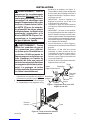
INSTALLATION
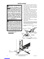
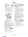
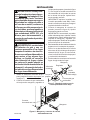
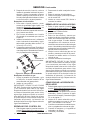
2. Connect fuel gas connector fitting on
hose/regulator assembly to propane
tank(s) (see Figure 7). Turn counterclock-
wise into threads on tank valve. Tighten
rmly using wrench.
IMPORTANT: Tighten regulator with vent
pointing down. Pointing vent down pro-
tects regulator from weather damage.
3. Connect hose to inlet connector (see
Figure 8). Tighten rmly using a wrench.
IMPORTANT: Extra hose or piping may be
used if needed. Install extra hose or piping
between hose/regulator assembly and
propane tank. You must use the regulator
supplied with heater.
4. Open propane supply valve on propane
tank(s) slowly.
Note: If not opened slowly, excess ow
check valve on propane tank will stop gas
ow. If this happens, close propane supply
valve and open again slowly.
5. Check all connections for leaks. Correct
all leaks.
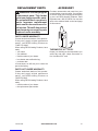
Figure 7 - Regulator With Vent Pointing
Down
Hose
Regulator
Vent
(pointing
down)
Fuel Gas
Connector
Supply Valve
Propane
Tank
Figure 8 - Hose and Inlet Connector
Hose
Inlet
Connector
WARNING: Review and un-
derstand the warnings in the
Safety section, page 2. They are
needed to safely operate this
heater. Follow all local codes or
in the absence of local codes,
with the Standard for Grand-
stands, Folding and Telescopic
Seating, Tents and Membrane
Structures NFPA 102 and the
Standard for Storage and Han-
dling of Liquieed Petroleum
Gases ANSI/NFPA 58.
WARNING: Test all gas piping
and connections for leaks after
installation or servicing. Never
use an open ame to check for a
leak. Apply a noncorrosive leak
detection uid to all joints (avail-
able at local plumbing supply
stores). Bubbles forming show a
leak. Correct all leaks at once.
1. Provide propane supply system (see
Propane Supply, page 6).

www.desatech.com
120193-01A 11
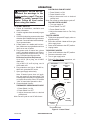
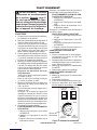
OPERATION
CONTINUOUS FAN WITH HEAT
1. Press Switch 1 to ON.
2. Press Switch 2 to ON.
3. Adjust thermostat knob to desired
comfort level.
Note: Fan will stay on when burner cycles off.
FAN ONLY WITH NO HEAT
1. Turn gas supply off.
2. Press Switch 1 to OFF.
3. Press Switch 2 to ON.
4. Adjust thermostat knob to Fan Only
position.
TO STOP HEATER
1. Tightly close propane/LP supply valve on
propane tank(s).
2. Wait a few seconds. Heater will burn gas
left in supply hose.
3. Press on/off switches to the OFF position.
4. Unplug heater.
TO RESTART HEATER
1. Press on/off switches to the OFF position.
2. Reconnect extension cord.
3. Turn on gas supply valve.
4. Follow To Start Heater instructions, col-
umn 1.
Thermostat
Fan Cycle
ON
OFF
Switch 1
Fan
Continuous
ON
THERMOSTAT
CYCLE
LOW
Fan Only
HIGH
OFF
Switch 2
8
1
2
3
4
5
6
7
Thermostat Knob
Figure 9 - Control Panel
WARNING: Review and un-
derstand the warnings in the
Safety section, page 2. They are
needed to safely operate this
heater. Follow all local codes
when using this heater.
TO START HEATER
1. Follow all installation, ventilation and
safety information.
2. Connect regulator/hose assembly to gas
supply.
3. Check for leaks using a noncorrosive leak
detection uid. Bubbles forming indicate a
gas leak. Correct all leaks before attempt-
ing to operate heater.
4. Locate heater on a stable and level sur-
face. Make sure strong drafts do not blow
into front or rear of heater.
5. Plug power cord of heater into a three
prong, grounded extension cord. Exten-
sion cord must be at least 6 feet (1.83 m)
long, CSA listed and of proper size.
Extension Cord Size Requirement
Up to 100 ft. (30 m) long, use 16 AWG
rated cord.
101 to 200 ft. (31 to 60 m) long, use 14
AWG rated cord.
6. Plug extension cord into a 120v/60 hz,
three hole, grounded GFI outlet.
7. Open gas supply valve slowly.
Note: If heater burner does not ignite,
turn gas supply off and open slowly. The
hose/regulator assembly is equipped with
an excess ow safety valve. An audible
"click" is heard when opened too fast.
8. Choose desired function:
THERMOSTAT OPERATION WITH HEAT
1. Press Switch 1 to ON.
2. Press Switch 2 to OFF.
3. Adjust thermostat knob to desired
comfort level.
Note: Fan will cycle on and off with burner.

www.desatech.com 120193-01A12
STORAGE
2. Place plastic cover caps over brass ttings
on inlet connector and hose/regulator as-
sembly.
3. Store in dry, clean, and safe place.
4. When taking heater out of storage, always
check inside of heater. Insects and small
animals may place foreign objects in
heater. Keep inside of heater free from
combustible and foreign objects.
CAUTION: Disconnect heater
from propane supply tank(s).
1. Store propane tank(s) in safe manner. See
Chapter 5 of Standard for Storage and
Handling of Liqueed Petroleum Gases,
ANSI/NFPA 58 and the Natural Gas and
Propane Installation Code CSA B149.1.
Follow all local codes. Always store pro-
pane tanks outdoors.
MAINTENANCE
WARNINGS
• Never service heater while it
is plugged in, connected to
propane supply, operating, or
hot. Severe burns and electri-
cal shock can occur.
• Keep heater clear and free
from combustible materials,
gasoline, and other ammable
vapors and liquids.
• Do not block the ow of com-
bustion or ventilation air.
1. Keep heater clean. Clean heater annually
or as needed to remove dust and debris. If
heater is dirty or dusty, clean heater with
a damp cloth. Use household cleaners on
difcult spots.
2. Inspect heater before each use. Check
connections for leaks. Apply a noncor-
rosive leak detection uid to connections.
Bubbles forming show a leak. Correct all
leaks at once.
3. Inspect hose/regulator assembly before
each use. If hose is highly worn or cut,
replace with one specied by manufac-
turer.
4. Have heater inspected yearly by a quali-
ed service agency.
5. Keep inside of heater free from combus-
tible and foreign objects. Remove motor
and other internal parts if needed to clean
inside of heater (see Service, below).
Burner
Check burner air inlet after every 300 hours
of operation to ensure burner air inlet is free
of dust or debris. Use compressed air (30 PSI
or less) to clean out burner air inlet.
SERVICE
WARNING: Never service
heater while it is plugged in,
connected to propane supply,
operating, or hot. Severe burns
and electrical shock can occur.
IMPORTANT: CHECK FOR GAS LEAKS. Test
all gas piping and connections for leaks after
installation or servicing. Never use an open
ame to check for a leak. Apply a noncorrosive
leak detection uid to all joints (available at lo-
cal plumbing supply stores). Bubbles forming
show a leak. Correct all leaks at once.

www.desatech.com
120193-01A 13
SERVICE
Continued
ELECTRICAL AND GAS TRAIN
COMPONENT ACCESS
1. Remove top (see Top and Side Panel
Removal, above).
2. Locate wiring diagram on inside of side
panel or go to page 19.
3. Check that all wiring terminals are se-
curely connected.
4. Check for gas leaks around ttings and
tubing of plumbing connections. See
page 10.
TOP AND SIDE PANEL REMOVAL
1. Remove 8 screws securing top brackets
to body panels. Remove top and set aside
(see Figure 10).
Brackets
Located
Underneath
Figure 10 - Removing Top and Side Panel
Side
Panel
Top
Bracket
Screws
Side Panel
Screw
2. Remove 2 screws securing side panel
at top edge. Remove 3 screws at lower
outside edge (see Figure 10). Push down
and lift out side panel.
MOTOR AND BLOWER ASSEMBLY
1. Remove top (see Top and Side Panel
Removal, above).
2. Remove 4 screws securing outlet louver
to front panel (see Figure 11, page 14).
3. Follow wires from blower/motor and dis-
connect from terminal blocks. Pull wires
out and coil excess to prevent damage to
insulation.
4. Remove 9 screws securing blower mount-
ing panel (see Figure 11, page 14). Bend
bafe top up and carefully lift entire as-
sembly out of heater.
5. Remove 4 nuts securing blower/motor to
mounting panel.
6. Attach new blower/motor to mounting
panel and reinstall in reverse order. Use
care when removing or installing blower
to mounting panel to avoid damage to
wiring. Reattach wiring referring to Wiring
Diagram on page 19.

www.desatech.com 120193-01A14
Outlet Louver
Figure 11 - Removing Blower/Motor Assembly
Terminal
Blocks
Blower/Motor
Blower
Mounting
Panel
Bafe Top
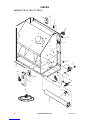
Figure 12 - Back Panel and Screen
Figure 13 - Removing Burner
Burner Solenoid Valve
Back Panel
Screen
BURNER, IGNITOR AND GAS
ORIFICE
WARNING: Make sure heater
is disconnected from propane and
electrical supply. Heater could
ignite causing severe burns.
Remove top (see Top and Side Panel Re-
moval, see page 13).
Replacing Burner
1. Remove all visible screws from lower sec-
tion of back panel and screen (see Figure
12). Pull back panel out to gain access to
screen. Push screen up and over ange,
then slide out.
2. Disconnect orange ignitor wire from ignit-
or. Ignitor is attached to back of burner.
3. Disconnect gas line at solenoid valve
and at orice using a 5/8" wrench. Avoid
bending and set aside.
4. Remove 3 screws securing burner to
partition (see Figure 13). Rotate burner
clockwise and pull out of chamber.
Note: There is a cutout on the partition
that allows the ignitor and bracket to slide
out as a complete assembly. Use caution
when removing or installing burner to avoid
damaging or dislocating ignitor electrode.
5. After all service is complete, reinstall
burner in reverse order. Support burner
SERVICE
Continued
while inserting burner locator pin into hole
in chamber end panel. Replace screen
and back panel.

www.desatech.com
120193-01A 15
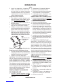
Replacing Ignitor
1. To loosen back panel and gain access
to ignitor, follow step 1 under Replacing
Burner, page 14.
2. Remove ignitor bracket screw and lift
ignitor.
3. Attach new ignitor with ignitor mounting
screw removed in step 2.
4. Install new ignitor. Ignitor gap between
ignitor electrode and burner deck is
0.13"/0.15" (3.3/3.8 mm).
5. Test for spark. Plug into extension cord
and watch for spark between ignitor
electrode and burner deck.
SERVICE
Continued
Ignitor Gap
Figure 14 - Ignitor Gap
Replacing Gas Orice
1. Hold burner flange and rotate orifice
counterclockwise to remove.
2. Install new orice
IMPORTANT: CHECK FOR GAS LEAKS. Test
all gas piping and connections for leaks after
installation or servicing. Never use an open
ame to check for a leak. Apply a noncorrosive
leak detection uid to all joints (available at lo-
cal plumbing supply stores). Bubbles forming
show a leak. Correct all leaks at once.
REPLACING DSI CONTROL
1. Remove top (see Top Panel Removal,
page 13).
2. Disconnect orange ignitor wire.
3. Remove white wire connector.
4. Remove 2 screws and nuts securing DSI
control.
5. Install new DSI control. Reconnect wiring.
REPLACING GAS VALVE
1. Remove top (see Top and Side Panel
Removal, page 13).
2. Disconnect 2 blue wires.
3. Remove gas line.
4. Remove 2 screws and nuts holding valve
to mounting plate.
5. Remove brass ttings from old gas valve.
If damaged replace with new fittings.
Install ttings into new gas valve. Use
pipe joint sealant that is resistant to liquid
petroleum (LP) gas. Tighten all ttings.
6. Install new gas valve using screws and
nuts from step 4.
7. Connect blue wires to new gas valve.
8. Reconnect gas line.
IMPORTANT: CHECK FOR GAS LEAKS. Test
all gas piping and connections for leaks after
installation or servicing. Never use an open
ame to check for a leak. Apply a noncorrosive
leak detection uid to all joints (available at lo-
cal plumbing supply stores). Bubbles forming
show a leak. Correct all leaks at once.
CHECKING REGULATOR
PRESSURE
1. Remove top (see Top Panel Removal,
page 13).
2. Locate pressure tap on solenoid valve and
remove (retain plug for later installation).
See Figure 15, page 16.
3. Install 1/8 NPT barb tting with sealant on
threads into solenoid valve.
4. Connect to manometer or pressure gauge
that measures in inches of water.
5. Connect hose and regulator to heater and
tank.
6. Plug in and turn on.

www.desatech.com 120193-01A16
SPECIFICATIONS
• Output Rating - 125,000 Btu/Hr (131,882 kJ/Hr)
• Fuel Consumption - 1.4 Gal/Hr (5.2 Liters/Hr), 5.8 lb/Hr (2.6 kg/Hr)
• Propane Vapor Fuel Only
• Manifold Pressure - 10" (25.4 cm) WC
• Supply Pressure To Regulator: Minimum (for purposes of input adjustment) 10 psi (69 kPa),
Maximum - Tank Pressure
• Regulator Outlet Pressure - 11" wc
• Electric Input - 120 V/60 Hz
• Amperage - Start 7, Run 3.5
• Load - 10 amps on receptacle
• Hot Air Output (Approx) - 1000 CFM (28.3 m3/min)
• Motor - 1,100 RPM, 1/4 HP
• Ignition - Electronic Direct Spark Ignition (D.S.I.)
• Ignitor Gap - 0.12"/0.15" (3.1/3.8 mm)
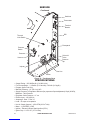
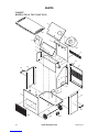
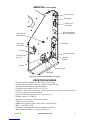
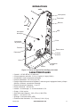
Figure 15 - Tent Heater Parts
Solenoid
Valve
Receptacle
DSI
Terminal
Boards
Thermostat
Switches
Gas Line
Burner
Pressure
Switch
SERVICE
Continued
Vacuum
Pressure
Pressure
Tap
Thermal
Limit Switch
Injector

www.desatech.com
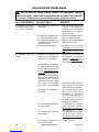
120193-01A 17
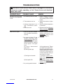
REMEDY
1. Check voltage to electrical
outlet. If voltage is good,
check heater power cord for
breaks
2. Adjust thermostat to higher
setting
3. Wait for ambient temperature
to decrease
4. Replace motor. See Motor and
Blower Assembly, page 13
1. Repeat installation and op-
eration instructions. See
Installation, page 10 and
Operation, page 11
2.
A) Check ignitor wire. Tighten
or reattach loose ignitor wire.
B) Assure gap between ignitor
electrode and burner deck is
0.13"/0.15" (3.3/3.8 mm). Do
not bend electrode. Doing so
may cause it to break
C) Replace ignitor elec-
trode. See Replacing Ig-
nitor, page 15
D) Replace spark trans-
former. See Replacing DSI
Control, page 15
3. Clean tubing
POSSIBLE CAUSE
1. No electrical power to heater
2. Thermostat set too low
3. Ambient temperature is too
high. Thermostat is satis-
ed
4. Defective motor
1. User did not follow installa-
tion or operation instructions
properly
2. No spark at ignitor. To test
for spark, follow step 5 under
Replacing Ignitor, page 15. If
you see spark at ignitor, have
heater serviced by qualied
service person. If no spark
seen:
A) Loose or disconnected
ignitor wire
B) Wrong spark gap
C) Bad ignitor electrode
D) Bad spark DSI
3. Air proving switch blocked
OBSERVED FAULT
Fan does not turn when
switch(s) 1 or 2 are pressed
to ON
Heater will not ignite
TROUBLESHOOTING
WARNING: Never service heater while it is plugged in, connected
to propane supply, operating, or hot. Severe burns and electrical
shock can occur.

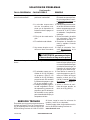
www.desatech.com 120193-01A18
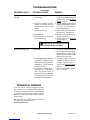
WARNING: Use only in areas
free of high dust content.
TROUBLESHOOTING
Continued
REMEDY
1. A) Rell tank
B) Provide additional and/or
larger tanks. See Propane
Supply, page 6
2. This can happen when running
heater in temperatures above
85° F (29˚ C). Run heater in
cooler temperatures
3. Check heater inlet and outlet.
Remove any obstructions
4.
Replace motor and blower as-
sembly. See page 13
5. Clean heater. See Mainte-
nance, page 12
1. Check all connections for
leaks. Apply noncorrosive leak
detection uid to gas joints.
Bubbles forming show a leak
that must be corrected
2. To obtain correct mixture of
propane/LP gas and air, use
a larger cylinder size, i.e.
100 lb. See Propane Supply,
page 6
3. Use a larger supply cylinder
size, i.e. 100 lb.
POSSIBLE CAUSE
1. Propane supply may be
inadequate
2. High surrounding air tem-
perature causing thermal
limit device to shut down
heater
3. Restricted air ow
4. Damaged fan
5. Excessive dust or debris in
surrounding area
1. Gas leak
2. Heater operating on a 20 lb.
propane/LP cylinder. Insuf-
cient propane/LP gas will be
supplied by a 20 lb. cylinder
resulting in odor
3. Propane/LP supply tank is
"freezing up". Evaporation
and consumption rate of
propane/LP from supply tank
is to great for the size of the
tank and air temperature
OBSERVED FAULT
Heater shuts down while
running
Heater producing odor
TECHNICAL SERVICE
You may have further questions about
this heater. If so, contact DESA Heating
Products’ Technical Service Department
at 1-866-672-6040. When calling, please
have your model and serial numbers of your
heater ready.
You can also visit DESA Heating Products’
Technical Service web site at
www.desatech.com.

www.desatech.com
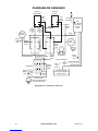
120193-01A 19
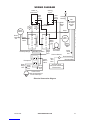
WIRING DIAGRAM
Electrical Connection Diagram
Motor
Moteur
VAC
Switch(4)
Thermostat
Termostato
Receptacle(6)
Switch 1
Cycle(1)
White
Blanco/Blanc
White
Blanco/Blanc
White
Blanco
Blanc
White
Blanco
Blanc
White/Blanco/Blanc
White
Blanco
Blanc
White/Blanco/Blanc
Solenoid Valve/
Válvula de solenoide/
Électrovanne
DSI
(encendedor
de chispa
directa)
AED
Black
Negro
Noir
Black
Negro
Noir
Black
Negro
Noir
Black
Negro
Noir
Black
Negro
Noir
Orange
Naranja
Black
Negro
Noir
Green
Verde
Vert
Green
Verde
Vert
Green
Verde
Vert
Green
Verde
Vert
Blue
Azul
Bleu
Blue/Azul/Bleu
Blue/Azul/Bleu
Red/Rojo/Rouge
Red
Rojo
Rouge
Red
Rojo
Rouge
Terminal Block(3)
Terminal Block(3)
Switch 2
Continuous(2)
(1) Interruptor 1 ciclo automático/
Interrupteur 1 en cycle
(2) Interruptor 2 continuo/
Interrupteur 2 en continu
(3) Bloque de terminales/Bornier
(4) Interruptor de VCA/
Interrupteur V c.a.
(5) Interruptor térmico/
Interrupteur thermique
(6) Receptáculo/Prise
Power Cord/
Cable de alimentación/
Cordon électrique
Thermal Switch(5)
Motor
Moteur
White
Blanco/Blanc
White/Blanco/Blanc
S1 = Switch 1(1)
S2 = Switch 2(2)
VAC = VAC Switch(4)
T/S = Thermal Switch(5)
T = Thermostat
Neutral
Neutro
Neutre
White
Blanco
Blanc
Black
Negro/Noir
Black
Negro/Noir
Black
Negro/Noir
Black
Negro
Noir
Black
Negro
Noir
Blue
Azul
Bleu
Blue/Azul/Bleu
Blue/Azul/Bleu
T
L1
DSI
VAC
S2
Receptacle(6)
S1
Solenoid
Valve
Ignitor
Encendedor
Allumeur Orange
Naranja
T/S
L2
Red/Rojo
Rouge
Red
Rojo
Rouge

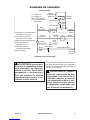
www.desatech.com 120193-01A20
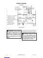
Ladder Diagram
WARNING: Never attempt
to service heater while it is
plugged in, operating, or hot.
Burns and electrical shock could
result. Only a qualied service
person should service or repair
heater.
WIRING DIAGRAM
Continued
If any of the original wire as supplied with
the appliance must be replaced, it must be
replaced with 105° C wire or it’s equivalent.
WARNING: Label all wires
prior to disconnection when
servicing controls. Wiring errors
can cause improper and dan-
gerous operation. Verify proper
operation after servicing.
Motor
Moteur
VAC
Switch(4)
Thermostat
Termostato
Receptacle(6)
Switch 1
Cycle(1)
White
Blanco/Blanc
White
Blanco/Blanc
White
Blanco
Blanc
White
Blanco
Blanc
White/Blanco/Blanc
White
Blanco
Blanc
White/Blanco/Blanc
Solenoid Valve/
Válvula de solenoide/
Électrovanne
DSI
(encendedor
de chispa
directa)
AED
Black
Negro
Noir
Black
Negro
Noir
Black
Negro
Noir
Black
Negro
Noir
Black
Negro
Noir
Orange
Naranja
Black
Negro
Noir
Green
Verde
Vert
Green
Verde
Vert
Green
Verde
Vert
Green
Verde
Vert
Blue
Azul
Bleu
Blue/Azul/Bleu
Blue/Azul/Bleu
Red/Rojo/Rouge
Red
Rojo
Rouge
Red
Rojo
Rouge
Terminal Block(3)
Terminal Block(3)
Switch 2
Continuous(2)
(1) Interruptor 1 ciclo automático/
Interrupteur 1 en cycle
(2) Interruptor 2 continuo/
Interrupteur 2 en continu
(3) Bloque de terminales/Bornier
(4) Interruptor de VCA/
Interrupteur V c.a.
(5) Interruptor térmico/
Interrupteur thermique
(6) Receptáculo/Prise
Power Cord/
Cable de alimentación/
Cordon électrique
Thermal Switch(5)
Motor
Moteur
White
Blanco/Blanc
White/Blanco/Blanc
S1 = Switch 1(1)
S2 = Switch 2(2)
VAC = VAC Switch(4)
T/S = Thermal Switch(5)
T = Thermostat
Neutral
Neutro
Neutre
White
Blanco
Blanc
Black
Negro/Noir
Black
Negro/Noir
Black
Negro/Noir
Black
Negro
Noir
Black
Negro
Noir
Blue
Azul
Bleu
Blue/Azul/Bleu
Blue/Azul/Bleu
T
L1
DSI
VAC
S2
Receptacle(6)
S1
Solenoid
Valve
Ignitor
Encendedor
Allumeur Orange
Naranja
T/S
L2
Red/Rojo
Rouge
Red
Rojo
Rouge
La page charge ...
La page charge ...
La page charge ...
La page charge ...
La page charge ...
La page charge ...
La page charge ...
La page charge ...
La page charge ...
La page charge ...
La page charge ...
La page charge ...
La page charge ...
La page charge ...
La page charge ...
La page charge ...
La page charge ...
La page charge ...
La page charge ...
La page charge ...
La page charge ...
La page charge ...
La page charge ...
La page charge ...
La page charge ...
La page charge ...
La page charge ...
La page charge ...
La page charge ...
La page charge ...
La page charge ...
La page charge ...
La page charge ...
La page charge ...
La page charge ...
La page charge ...
La page charge ...
La page charge ...
La page charge ...
La page charge ...
La page charge ...
La page charge ...
La page charge ...
La page charge ...
La page charge ...
La page charge ...
La page charge ...
La page charge ...
La page charge ...
La page charge ...
La page charge ...
La page charge ...
La page charge ...
La page charge ...
La page charge ...
La page charge ...
La page charge ...
La page charge ...
La page charge ...
La page charge ...
La page charge ...
La page charge ...
La page charge ...
La page charge ...
-
 1
1
-
 2
2
-
 3
3
-
 4
4
-
 5
5
-
 6
6
-
 7
7
-
 8
8
-
 9
9
-
 10
10
-
 11
11
-
 12
12
-
 13
13
-
 14
14
-
 15
15
-
 16
16
-
 17
17
-
 18
18
-
 19
19
-
 20
20
-
 21
21
-
 22
22
-
 23
23
-
 24
24
-
 25
25
-
 26
26
-
 27
27
-
 28
28
-
 29
29
-
 30
30
-
 31
31
-
 32
32
-
 33
33
-
 34
34
-
 35
35
-
 36
36
-
 37
37
-
 38
38
-
 39
39
-
 40
40
-
 41
41
-
 42
42
-
 43
43
-
 44
44
-
 45
45
-
 46
46
-
 47
47
-
 48
48
-
 49
49
-
 50
50
-
 51
51
-
 52
52
-
 53
53
-
 54
54
-
 55
55
-
 56
56
-
 57
57
-
 58
58
-
 59
59
-
 60
60
-
 61
61
-
 62
62
-
 63
63
-
 64
64
-
 65
65
-
 66
66
-
 67
67
-
 68
68
-
 69
69
-
 70
70
-
 71
71
-
 72
72
-
 73
73
-
 74
74
-
 75
75
-
 76
76
-
 77
77
-
 78
78
-
 79
79
-
 80
80
-
 81
81
-
 82
82
-
 83
83
-
 84
84


Master TB117 Le manuel du propriétaire
- Catégorie
- Congélateurs
- Taper
- Le manuel du propriétaire
- Ce manuel convient également à
dans d''autres langues
Documents connexes
Autres documents
-
Desa SPC-21PHTSA Manuel utilisateur
-
-
-
Desa TB110 85 Manuel utilisateur
-
-
-
-
-
-
Hubbell Wiring Device-Kellems PD1601 Guide d'installation