Hach ORBISPHERE 3650 Atex Manuel utilisateur
- Catégorie
- Densitomètres
- Taper
- Manuel utilisateur

DOC024.52.93004
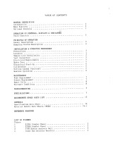
ORBISPHERE Model 3650 Atex
USER MANUAL
10/2019, Edition 13

2

1
Table of Contents
Section 1 General Information ......................................................................................................... 3
1.1 Safety information ........................................................................................................................ 3
1.1.1 Use of hazard information................................................................................................... 3
1.1.2 Service and repairs ............................................................................................................. 3
1.1.3 Interface box (model 29122) ...............................................................................................4
1.1.4 Precautionary labels............................................................................................................ 5
1.2 Intrinsically safe conformity.......................................................................................................... 6
1.3 Product recycling information....................................................................................................... 7
1.4 Product disposal .......................................................................................................................... 9
Section 2 Specifications and Certifications ............................................................................... 11
2.1 General technical data ............................................................................................................... 11
2.2 Analyzer gas and display options .............................................................................................. 11
2.3 Theory of operation.................................................................................................................... 12
2.3.1 Measuring oxygen............................................................................................................. 12
2.3.2 Measuring hydrogen ......................................................................................................... 12
2.4 3650Ex certificates..................................................................................................................... 13
Section 3 Installation........................................................................................................................ 17
3.1 Sensor installation...................................................................................................................... 18
3.2 Flow chamber installation .......................................................................................................... 18
3.3 Sample tube adapter (optional).................................................................................................. 19
3.4 WinLog97 PC program installation ............................................................................................19
3.5 Connections ............................................................................................................................... 19
3.5.1 3650Ex Instrument - PC connection ................................................................................. 19
3.6 Installation completion check list................................................................................................ 21
3.6.1 Battery............................................................................................................................... 21
3.6.2 Electrical connections ....................................................................................................... 21
3.6.3 Instrument clock setting .................................................................................................... 21
3.6.4 Electrochemical sensor..................................................................................................... 21
3.6.5 Flow chamber.................................................................................................................... 21
3.7 Storage when not used .............................................................................................................. 21
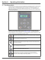
Section 4 Operating Information ................................................................................................... 23
4.1 Operating controls...................................................................................................................... 23
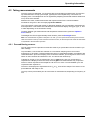
4.2 Taking measurements ............................................................................................................... 25
4.2.1 Preconditioning sensors.................................................................................................... 25
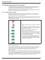
4.3 Storing measurements in the instrument ................................................................................... 26
4.3.1 Automatic data acquisition ................................................................................................26
4.3.2 Manual data acquisition .................................................................................................... 27
4.3.3 Viewing stored measurements.......................................................................................... 28
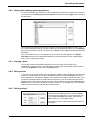
4.4 Storing and accessing measurements from the PC................................................................... 28
4.4.1 Downloading stored values............................................................................................... 28
4.4.2 Altering the sampling point descriptions............................................................................ 29
4.4.3 Copying values.................................................................................................................. 29
4.4.4 Saving values.................................................................................................................... 29
4.4.5 Printing values................................................................................................................... 29
4.4.6 Clearing stored values ...................................................................................................... 30
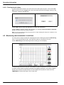
4.5 Monitoring measurements in real-time....................................................................................... 30
Section 5 Options Setup ................................................................................................................. 33
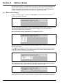
5.1 Main menu basics ...................................................................................................................... 33
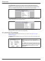
5.2 Instrument - PC connection ....................................................................................................... 34
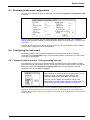
5.3 Reviewing instrument configuration ........................................................................................... 35
5.4 Configuring the instrument......................................................................................................... 35
5.4.1 Automatic data acquisition - Setting sampling intervals.................................................... 35
5.4.2 Membrane selection.......................................................................................................... 36
5.4.3 Selecting type of calibration .............................................................................................. 36

2
Table of Contents
5.4.4 Locking out the instrument’s CAL button...........................................................................37
5.4.5 Sensor calibration range checking ....................................................................................37
5.4.6 Entering a span gas value.................................................................................................37
5.4.7 Dual use (model 3650Ex/113 only) ...................................................................................38
Section 6 Calibrations......................................................................................................................39
6.1 Atmospheric pressure equilibrium..............................................................................................39
6.2 Pressure calibration....................................................................................................................39
6.3 Calibration range checking.........................................................................................................39
6.4 Sensor calibration.......................................................................................................................40
6.4.1 Calibration in a span gas...................................................................................................40
6.4.2 Calibration in line...............................................................................................................41
6.4.3 Calibration in air (oxygen sensors only) ............................................................................42
Section 7 Maintenance and Troubleshooting.............................................................................43
7.1 Maintenance...............................................................................................................................43
7.1.1 Instrument .........................................................................................................................43
7.1.2 Sensor ...............................................................................................................................43
7.2 Troubleshooting..........................................................................................................................43
7.2.1 Serial test ..........................................................................................................................43
7.2.2 Keyboard test ....................................................................................................................43
7.2.3 Display test........................................................................................................................44
7.2.4 Clock settings ....................................................................................................................44
7.2.5 Analog voltages view.........................................................................................................45
7.2.6 Measurements view ..........................................................................................................45
Section 8 Part Lists...........................................................................................................................47
8.1 Instrument configurations...........................................................................................................47
8.2 Spare parts.................................................................................................................................47
8.3 Accessories................................................................................................................................48

3
Section 1 General Information
In no event will the manufacturer be liable for direct, indirect, special, incidental or consequential
damages resulting from any defect or omission in this manual. The manufacturer reserves the
right to make changes in this manual and the products it describes at any time, without notice or
obligation. Revised editions are found on the manufacturer’s website..
1.1 Safety information
Please read this entire manual before unpacking, setting up or operating this equipment. Pay
attention to all danger and caution statements. Failure to do so could result in serious injury to
the operator or damage to the equipment.
Make sure that the protection provided by this equipment is not impaired. Do not use or install
this equipment in any manner other than that specified in this manual.
1.1.1 Use of hazard information
1.1.2 Service and repairs
None of the instrument’s components can be serviced by the user. Only personnel from Hach
are authorized to attempt repairs to the system and only components formally approved by the
manufacturer should be used. Any attempt at repairing the instrument in contravention of these
principles could cause damage to the instrument and corporal injury to the person carrying out
the repair. It renders the warranty null and void and could compromise the correct working of the
instrument and the electrical integrity or the CE compliance of the instrument.
If you have any problems with installation, starting, or using the instrument please contact the
company that sold it to you. If this is not possible, or if the results of this approach are not
satisfactory, please contact the manufacturer’s Customer Service.
NOTICE
The manufacturer is not responsible for any damages due to misapplication or misuse of this
product including, without limitation, direct, incidental and consequential damages, and
disclaims such damages to the full extent permitted under applicable law. The user is solely
responsible to identify critical application risks and install appropriate mechanisms to protect
processes during a possible equipment malfunction.
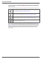
DANGER
Indicates a potentially or imminently hazardous situation which, if not avoided, will result in
death or serious injury.
WARNING
Indicates a potentially or imminently hazardous situation which, if not avoided, could result in
death or serious injury.
CAUTION
Indicates a potentially or imminently hazardous situation that may result in minor or moderate
injury.
NOTICE
Indicates a situation which, if not avoided, may cause damage to the instrument. Information
that requires special emphasis.

4
General Information
1.1.3 Interface box (model 29122)
WARNING
Explosion hazard. Only use the Interface Box 29122 in the safe area and never in the
explosive area.
WARNING
The interface box should only be connected to an earthed power supply socket.
WARNING
In accordance with safety standards, it must be possible to disconnect the external power
supply of the interface box in its immediate vicinity.
WARNING
Any maintenance of the interface box should be performed exclusively by personnel
specialized and authorized to work on electrical equipment, in accordance with relevant local
regulations.
WARNING
Disconnect the interface box from the power supply before carrying out any maintenance
(including changing fuses).
WARNING
Electrical danger and fire hazard. Only use the supplied power cable. Only qualified experts
may perform the tasks detailed in the installation section of this manual, while adhering to all
locally valid safety regulations.
WARNING
Removable power cables must not be replaced with inadequately dimensioned power cables.

5
General Information
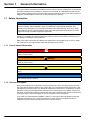
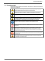
1.1.4 Precautionary labels
Read all labels and tags attached to the instrument. Personal injury or damage to the instrument
could occur if not observed.
This symbol, when noted on a product enclosure or barrier, indicates that a risk of electrical
shock and/or electrocution exists and indicates that only individuals qualified to work with
hazardous voltages should open the enclosure or remove the barrier.
This symbol, when noted on the product, indicates that the marked item can be hot and
should not be touched without care.
This symbol, when noted on the product, indicates the presence of devices sensitive to
electrostatic discharge and indicates that care must be taken to prevent damage to them.
This symbol, when noted on the product, identifies a risk of chemical harm and indicates that
only individuals qualified and trained to work with chemicals should handle chemicals or
perform maintenance on chemical delivery systems associated with the equipment.
This symbol, if noted on the product, indicates the need for protective eye wear.
This symbol, when noted on the product, identifies the location of the connection for protective
earth (ground).
Electrical equipment marked with this symbol may not be disposed of in European public
disposal systems. In conformity with European local and national regulations, European
electrical equipment users must now return old or end-of-life equipment to the manufacturer
for disposal at no charge to the user.
Products marked with this symbol indicates that the product contains toxic or hazardous
substances or elements. The number inside the symbol indicates the environmental protection
use period in years.
Products marked with this symbol indicates that the product must only be used in the safe
area
and never in the explosive area.

6
General Information
1.2 Intrinsically safe conformity
Orbisphere series 3650Ex analyzers for gas measurement have been certified as Intrinsically
Safe by:
LCIE (Laboratoire Central des Industries Electriques), 33 av. Division Leclerc,
Fontenay aux Roses 92260, France.
Note: LCIE is notified body number 0081 in accordance with the European ATEX Directive.
LCIE certifies that this electrical apparatus has been found to comply with the essential Health
and Safety Requirements: EN 60079-0, EN 60079-11.
These instruments are certified II 1G EX ia IIC T4 Ga under EC type Examination Certificate
number LCIE 03 ATEX 6003 X
Category Explanation
II 1 G ATEX marking: Surface apparatus with permanent explosive gas presence.
Ex Explosion-proof apparatus built to the universal standards that follow.
ia
Type of protection: The highest category, based on a safety factor of 1.5 on two faults.
No combination of two faults in the 3650Ex can produce a spark, or heating, causing
ignition of an explosive atmosphere.
IIC Gas group: Corresponds to the most flammable gases, including hydrogen.
T4 Temperature category: Maximum surface temperature of 135 ºC (250 ºF).
Ga Equipment protection level

7
General Information
1.3 Product recycling information
ENGLISH
Electrical equipment marked with this symbol may not be disposed of in
European public disposal systems after 12 August 2005. In conformity with
European local and national regulations (EU Directive 2002/96/EC), European
electrical equipment users must now return old or end-of-life equipment to the
manufacturer for disposal at no charge to the user.
Note: For return for recycling, please contact the equipment
manufacturer or supplier for instructions on how to return end-of-life
equipment for proper disposal.
DEUTSCH
Elektrogeräte, die mit diesem Symbol gekennzeichnet sind, dürfen in Europa nach dem 12.
August 2005 nicht mehr über die öffentliche Abfallentsorgung entsorgt werden. In
Übereinstimmung mit lokalen und nationalen europäischen Bestimmungen (EU-Richtlinie
2002/96/EC), müssen Benutzer von Elektrogeräten in Europa ab diesem Zeitpunkt alte bzw. zu
verschrottende Geräte zur Entsorgung kostenfrei an den Hersteller zurückgeben.
Hinweis: Bitte wenden Sie sich an den Hersteller bzw. an den Händler, von dem Sie das Gerät
bezogen haben, um Informationen zur Rückgabe des Altgeräts zur ordnungsgemäßen
Entsorgung zu erhalten.
FRANCAIS
A partir du 12 août 2005, il est interdit de mettre au rebut le matériel électrique marqué de ce
symbole par les voies habituelles de déchetterie publique. Conformément à la réglementation
européenne (directive UE 2002/96/EC), les utilisateurs de matériel électrique en Europe doivent
désormais retourner le matériel usé ou périmé au fabricant pour élimination, sans frais pour
l'utilisateur.
Remarque: Veuillez vous adresser au fabricant ou au fournisseur du matériel pour les
instructions de retour du matériel usé ou périmé aux fins d'élimination conforme.
ITALIANO
Le apparecchiature elettriche con apposto questo simbolo non possono essere smaltite nelle
discariche pubbliche europee successivamente al 12 agosto 2005. In conformità alle normative
europee locali e nazionali (Direttiva UE 2002/96/EC), gli utilizzatori europei di apparecchiature
elettriche devono restituire al produttore le apparecchiature vecchie o a fine vita per lo
smaltimento senza alcun costo a carico dell’utilizzatore.
Nota: Per conoscere le modalità di restituzione delle apparecchiature a fine vita da riciclare,
contattare il produttore o il fornitore dell’apparecchiatura per un corretto smaltimento.
DANSK
Elektriske apparater, der er mærket med dette symbol, må ikke bortskaffes i europæiske offentlige
affaldssystemer efter den 12. august 2005. I henhold til europæiske lokale og nationale regler
(EU-direktiv 2002/96/EF) skal europæiske brugere af elektriske apparater nu returnere gamle eller
udtjente apparater til producenten med henblik på bortskaffelse uden omkostninger for brugeren.
Bemærk: I forbindelse med returnering til genbrug skal du kontakte producenten eller
leverandøren af apparatet for at få instruktioner om, hvordan udtjente apparater bortskaffes
korrekt.

8
General Information
SVENSKA
Elektronikutrustning som är märkt med denna symbol kanske inte kan lämnas in på europeiska
offentliga sopstationer efter 2005-08-12. Enligt europeiska lokala och nationella föreskrifter
(EU-direktiv 2002/96/EC) måste användare av elektronikutrustning i Europa nu återlämna gammal
eller utrangerad utrustning till tillverkaren för kassering utan kostnad för användaren.
Obs! Om du ska återlämna utrustning för återvinning ska du kontakta tillverkaren av utrustningen
eller återförsäljaren för att få anvisningar om hur du återlämnar kasserad utrustning för att den ska
bortskaffas på rätt sätt.
ESPANOL
A partir del 12 de agosto de 2005, los equipos eléctricos que lleven este símbolo no deberán ser
desechados en los puntos limpios europeos. De conformidad con las normativas europeas
locales y nacionales (Directiva de la UE 2002/96/EC), a partir de esa fecha, los usuarios
europeos de equipos eléctricos deberán devolver los equipos usados u obsoletos al fabricante de
los mismos para su reciclado, sin coste alguno para el usuario.
Nota: Sírvase ponerse en contacto con el fabricante o proveedor de los equipos para solicitar
instrucciones sobre cómo devolver los equipos obsoletos para su correcto reciclado.
NEDERLANDS
Elektrische apparatuur die is voorzien van dit symbool mag na 12 augustus 2005 niet meer
worden afgevoerd naar Europese openbare afvalsystemen. Conform Europese lokale en
nationale wetgegeving (EU-richtlijn 2002/96/EC) dienen gebruikers van elektrische apparaten
voortaan hun oude of afgedankte apparatuur kosteloos voor recycling of vernietiging naar de
producent terug te brengen.
Nota: Als u apparatuur voor recycling terugbrengt, moet u contact opnemen met de producent of
leverancier voor instructies voor het terugbrengen van de afgedankte apparatuur voor een juiste
verwerking.
POLSKI
Sprzęt elektryczny oznaczony takim symbolem nie może być likwidowany w europejskich
systemach utylizacji po dniu 12 sierpnia 2005. Zgodnie z europejskimi, lokalnymi i państwowymi
przepisami prawa (Dyrektywa Unii Europejskiej 2002/96/EC), użytkownicy sprzętu elektrycznego
w Europie muszą obecie przekazywać Producentowi stary sprzęt lub sprzęt po okresie
użytkowania do bezpłatnej utylizacji.
Uwaga: Aby przekazać sprzęt do recyklingu, należy zwrócić się do producenta lub dostawcy
sprzętu w celu uzyskania instrukcji dotyczących procedur przekazywania do utylizacji sprzętu po
okresie użytkownia.
PORTUGUES
Qualquer equipamento eléctrico que ostente este símbolo não poderá ser eliminado através dos
sistemas públicos europeus de tratamento de resíduos sólidos a partir de 12 de Agosto de 2005.
De acordo com as normas locais e europeias (Directiva Europeia 2002/96/EC), os utilizadores
europeus de equipamentos eléctricos deverão agora devolver os seus equipamentos velhos ou
em fim de vida ao produtor para o respectivo tratamento sem quaisquer custos para o utilizador.
Nota: No que toca à devolução para reciclagem, por favor, contacte o produtor ou fornecedor do
equipamento para instruções de devolução de equipamento em fim de vida para a sua correcta
eliminação.

9
General Information
1.4 Product disposal
Note: The following only applies to European customers.
Hach is committed to ensuring that the risk of any environmental damage or pollution caused by
any of its products is minimized as far as possible. The European Waste Electrical and
Electronic Equipment (WEEE) Directive (2002/96/EC) that came into force on August 13 2005
aims to reduce the waste arising from electrical and electronic equipment; and improve the
environmental performance of all those involved in the life cycle of electrical and electronic
equipment.
In conformity with European local and national regulations (EU Directive 2002/96/EC stated
above), electrical equipment marked with the above symbol may not be disposed of in
European public disposal systems after 12 August 2005.
Hach will offer to take back (free of charge to the customer) any old, unserviceable or
redundant analyzers and systems which carry the above symbol, and which were originally
supplied by Hach. Hach will then be responsible for the disposal of this equipment.
In addition, Hach will offer to take back (at cost to the customer) any old, unserviceable or
redundant analyzers and systems which do not carry the above symbol, but which were
originally supplied by Hach. Hach will then be responsible for the disposal of this equipment.
Should you wish to arrange for the disposal of any piece of equipment originally supplied by
Hach, please contact your supplier or our After Sales Service department in for instructions on
how to return this equipment for proper disposal.

10
General Information

11
Section 2 Specifications and Certifications
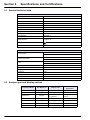
2.1 General technical data
2.2 Analyzer gas and display options
3650EX Instrument
Power Supply Model 32960 non-rechargeable lithium battery
Battery Autonomy 60 hours continuous use
Signal Drift < 0.5% of reading between service
Serial Output (RS232) Baud rate: 9600; Stop Bits: 1; Start Bits: 0; Parity: None;
Temperature Compensation Range -5 to 60°C
Instrument Operating Limits 0 to 45°C
Dimensions (HxWxD) 150 mm x 115 mm x 220 mm
Weight 2.4 kg
Enclosure IP 65/NEMA 4
EMC Directive EN 61326-1
ATEX Directive
EN 60079-0
EN 60079-11
LCIE 03 ATEX 6003 X II 1 G, EX ia IIC T4 Ga
ISO Certification ISO9001/EN29001
29122 Interface Box
Power Supply
120Vac 50/60Hz (Model 29122.A)
230Vac 50/60Hz (Model 29122.B)
Power Consumption
11VA (Model 29122.A)
7VA (Model 29122.B)
Fuse
Max current 250mA (Model 29122.A)
Max current 100mA (Model 29122.B)
Operating Limits 0 to 45°C
Dimensions (HxWxD) 70 mm x 140 mm x 190 mm
Weight 0.65 kg
Enclosure IP 20
Enclosure material ABS FR (V0)
EMC Directive EN 61326-1
LVD Directive EN 61010-1
Instrument Model Gas Measured Display Units
Maximum Display
Resolution
3650EX/111 Oxygen ppm/ppb (liquid) 1 ppb
3650EX/112 Oxygen %/ppm (gaseous) 1 ppm
3650EX/113 Oxygen
ppm (liquid)
% (gaseous)
0.001 ppm
0.001%
3650EX/114 Oxygen kPa/Pa (gaseous) 1 Pa
3650EX/115 Oxygen bar/mbar (gaseous) 1 mbar
3650EX/211 Hydrogen ppm/ppb (liquid) 0.01 ppb
3650EX/212 Hydrogen %/ppm (gaseous) 0.01 ppm

12
Specifications and Certifications
2.3 Theory of operation
2.3.1 Measuring oxygen
The sensor circuitry performs four functions:
• Applying a constant voltage to the anode
• Measuring the current flowing through the sensor
• Compensating this current for sample temperature variations
• Converting these resulting signals into a scaled current or voltage
The anode is held positive with respect to the cathode. Current flowing through the sensor due
to oxygen reduction at the cathode is converted to a voltage by an amplifier, the proportionality
between voltage and current being determined by the feedback resistance of this amplifier.
The output voltage is essentially a function of oxygen activity (partial pressure), temperature and
membrane permeability. Corrections for variations in membrane permeability are made when
the sensor is calibrated. The temperature compensation circuit accounts for temperature
variations. Hence the output voltage varies only with oxygen concentration.
2.3.2 Measuring hydrogen
The sensor circuitry performs four functions:
• Maintaining a zero potential to the anode
• Measuring the current flowing through the sensor
• Compensating this current for sample temperature variations
• Converting these resulting signals into a scaled current or voltage
The anode is held neutral with respect to the cathode. Current flowing through the sensor due to
hydrogen oxidation at the anode is converted to a voltage by an amplifier, the proportionality
between voltage and current being determined by the feedback resistance of this amplifier.
The output voltage is essentially a function of hydrogen activity (partial pressure), temperature
and membrane permeability. Corrections for variations in membrane permeability are made
when the sensor is calibrated. The temperature compensation circuit accounts for temperature
variations. Hence the output voltage varies only with hydrogen concentration.

13
Specifications and Certifications
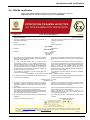
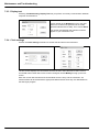
2.4 3650Ex certificates
Refer to the IECEx Database web site for the IECEx Certificate of conformity:
http://iecex.iec.ch, with the Certificate reference: LCI 09.0025X
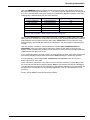
ATTESTATION D’EXAMEN UE DE TYPE
EU TYPE EXAMINATION CERTIFICATE
Seul le texte en français peut engager la responsabilité du LCIE. Ce document ne peut être reproduit que dans son intégralité, sans aucune modification. Il est établi
en accord avec le
référentiel de certification ATEX du LCIE. The LCIE’s liability applies only on the French text.
This document may only be reproduced in its entirety
and without any change. It is issued in accordance with LCIE’s ATEX Certification Rules.
CERT-ATEX-FORM 04 Rev. 02 Page 1 / 4
1
Version
: 04
LCIE 03 ATEX 6003 X
Issue
: 04
Directive 2014/34/UE
Directive 2014/34/EU
2
Appareil ou Système de Protection destiné à être utilisé en
Atmosphères Explosibles
Equipment or Protective System Intended for use in Potentially
Explosive Atmospheres
3
Produit :
Product :
MicroLogger portable
Portable MicroLogger
Type: 3650EX
4
Fabricant :
Manufacturer :
HACH LANGE Sàrl
5
Adresse :
Address :
6, route de Compois
1222 Vésenaz
Switzerland
6
Ce produit et ses variantes éventuelles acceptées sont décrits
dans I'annexe de la présente attestation et dans les documents
descriptifs cités en référence.
This product any acceptable variation thereto is specified in the
schedule to this certificate and the documents therein referred
to.
7
Le LCIE, Organisme Notifié sous la référence 0081
conformément à l’article 17 de la directive 2014/34/UE du
Parlement européen et du Conseil du 26 février 2014, certifie
que
ce produit
est conforme aux Exigences Essentielles de
Sécurité et de Santé pour la conception et la construction de
produits
destinés à être utilisés en atmosphères explosibles,
données dans l’annexe II de la Directive.
LCIE, Notified Body number 0081 in accordance with article 17
of the Directive 2014/34/EU of the European Parliament and
the Council of 26 February 2014 certifies that
product has
been
found to comply with the Essential Health and Safety
Requirements relating to the design and construction of
products intended for use in potentially explosive atmospheres,
given in Annex II to the Directive.
Les résultats des vérifications et essais figurent dans le(s)
rapport(s) confidentiel(s) N° :
The examination and test results are recorded in confidential
report(s) N°:
143781-690891, 112767-624064-1, 89388-580763-1, 60022484-515730-1, 60001647-1
8
Le respect des Exigences Essentielles de Sécurité et de Santé
est assuré par la conformité à :
Compliance with the Essential Health and Safety Requirements
has been assured by compliance with :
EN 60079-0:2012 + A11:2013
EN 60079-11:2012
9
Le signe « X » lorsqu'il est placé à la suite du numéro de
l’attestation, indique que cet appareil est soumis aux conditions
particulières
d’utilisation
, mentionnées dans l’annexe de cette
attestation.
If the sign “X” is placed after the certificate number, it indicates
that the
product is subject to
the Specific Conditions of Use
specified in the schedule to this certificate.
10
Cette Attestation d'Examen UE de Type concerne uniquement
la conception et la construction du produit spécifié.
This EU Type Examination Certificate relates only to the design
and construction of the specified product.
Des exigences supplémentaires de la directive sont applicables
pour la fabrication et la fourniture
du produit
. Ces dernières ne
sont pas couvertes par la présente attestation.
Further requirements of the Directive apply to the
manufacturing process and s
upply of this product
. These are
not covered by this certificate.
11
Le marquage du produit est mentionné dans l’annexe de cette
attestation.
The marking of the product is specified in the schedule to this
certificate.
Fontenay-aux-Roses, le 25 juillet 2017
Responsable de Certification
Certification Officer
Julien Gauthier
Ce
Ce
Ce
rt
rt
r
r
r
r
ification
Officer
Ju
Ju
Ju
uu
Ju
Ju
u
J
Ju
u
Ju
u
Ju
Ju
Ju
u
u
u
J
J
u
u
J
li
li
l
li
l
i
li
e
e
e
e
e
en
e
e
e
e
e
e
e
e
e
e
e
e
e
e
e
e
e
e
G
G
auau
au
au
au
u
u
u
au
au
u
u
au
au
au
au
au
au
au
a
au
u
u
au
a
au
au
u
au
u
au
u
a
u
au
a
u
u
u
u
a
u
a
au
u
a
a
u
u
u
th
th
th
th
th
th
t
t
t
h
t
h
h
h
h
ie
r

14
Specifications and Certifications
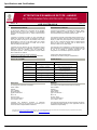
ATTESTATION D’EXAMEN UE DE TYPE - ANNEXE
EU TYPE EXAMINATION CERTIFICATE - SCHEDULE
Seul le texte en français peut engager la responsabilité du LCIE. Ce document ne peut être reproduit que dans son intégralité, sans aucune modification. Il est établi
en accord avec le
référentiel de certification ATEX du LCIE. The LCIE’s liability applies only on the French text.
This document may only be reproduced in its entirety
and without any change. It is issued in accordance with LCIE’s ATEX Certification Rules.
CERT-ATEX-FORM 04 Rev. 02 Page 2 / 4
1
Version
: 04
LCIE 03 ATEX 6003 X
Issue
: 04
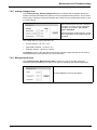
12
DESCRIPTION DU PRODUIT
DESCRIPTION OF PRODUCT
Le MicroLogger 3650EX est un analyseur de gaz portable,
alimenté par pile, conçu pour mesurer la concentration
d’oxygène ou d’hydrogène avec un capteur électrochimique
externe
.
The MicroLogger 3650EX is a portable gas analyzer, battery
powered, designed to measure oxygen or hydrogen gas
concentration with external electrochemical
sensor.
L’appareil se compose d’un boitier en acier inoxydable (la
façade et le support de la sonde en aluminium), d’un écran
LCD, d’un clavier couvert par un film plastique, deux cartes
électroniques et une pile. Il doit être équipé d’un capteur
électrochimique de type 31xxxE ou X1Y0E, avec ou sans
câble de rallonge de 3m à 999m.
L’appareil
peut être alimenté
par une alimentation externe
quand il est raccordé à un ordinateur à travers un boitier
d’interface, mais son utilisation n’est pas autorisée en
atmosphère explosive.
Cette configuration n’est pas certifiée
dans le cadre de ce certificat.
The equipment consists of a stainless steel enclosure (front of
enclosure and sensor frame are made of aluminum), a LCD
display, a plastic film panel keyboard, two electronic boards
and one cell. It shall be equipped with an electrochemical
sensor of type 31xxxE or X1Y0E, with or without sensor
extension cable of 3m to 999m length.
The equipment can be powered
by an external power supply
when connected to a computer through an interface box, but
its use is not allowed in explosive atmosphere. This
configuration is n
ot certified as part of this certificate.
Paramètres électriques de sécurité intrinsèque:
Intrinsic safety electrical parameters:
Alimenté par une pile lithium 3.6V, de type LS 26500 SAFT
Powered by 3.6V lithium cell type LS 26500 SAFT
DETAIL DE LA GAMME
RANGE DETAILS
Modèle / Model
Gaz mesuré / Gas measured
Affichage des unités / Display units
3650EX/111
Oxygène / Oxygen ppm/ppb (liquide/liquid)
3650EX/112
Oxygène / Oxygen %/ppm (gazeux/gaseaous)
3650EX/113
Oxygène / Oxygen
ppm (liquide/liquid)
% (gazeux/gaseous)
3650EX/114
Oxygène / Oxygen kPa/Pa (gazeux/gaseous)
3650EX/115
Oxygène / Oxygen bar/mbar (gazeux/gaseous)
3650EX/211
Hydrogène / Hydrogen
ppm/ppb (liquide/liquid)
3650EX/212
Hydrogène / Hydrogen
%/ppm (gazeux/gaseous)
MARQUAGE
MARKING
Le marquage du produit doit comprendre :
The marking of the product shall include the following :
HACH LANGE
Adresse
: …
Type :
3650EX
N° de fabrication
: …
Année de fabrication
: …
F
II 1 G
Ex ia IIC T
4 Ga
LCIE
03 ATEX 6003 X
0°C ≤ Tamb ≤ +45°C
HACH LANGE
Address:
…
Type:
3650EX
Serial number: …
Year of
construction: …
F
II 1 G
Ex ia IIC T4 Ga
LCIE
03 ATEX 6003 X
0°C ≤ Tamb ≤ +45°C
L’appareil doit également comporter le marquage
normalement prévu par
les normes de construction qui le
concernent sous la responsabilité du fabricant.
The equipment shall also bear the usual marking required by
the
product
standards applying to such equipment under the
manufacturer responsibility.

15
Specifications and Certifications
ATTESTATION D’EXAMEN UE DE TYPE - ANNEXE
EU TYPE EXAMINATION CERTIFICATE - SCHEDULE
Seul le texte en français peut engager la responsabilité du LCIE. Ce document ne peut être reproduit que dans son intégralité, sans aucune modification. Il est établi
en accord avec le
référentiel de certification ATEX du LCIE. The LCIE’s liability applies only on the French text.
This document may only be reproduced in its entirety
and without any change. It is issued in accordance with LCIE’s ATEX Certification Rules.
CERT-ATEX-FORM 04 Rev. 02 Page 3 / 4
1
Version
: 04
LCIE 03 ATEX 6003 X
Issue
: 04
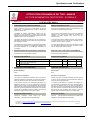
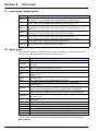
13
CONDITIONS PARTICULIERES D'UTILISATION
SPECIFIC CONDITIONS OF USE
Utiliser uniquement une pile non rechargeable de type LS
26500 SAFT. Le remplacement de la pile en atmosphère
explosive est autorisé.
Use only non-rechargeable cell of type LS 26500 SAFT. Cell
replacement is allowed in explosive area.
L’utilisation de l’entrée d’alimentation externe n’est pas
autorisée en zone dangereuse. La liaison externe doit être
équipée d’une protection pour limitation de tension lors de son
utilisation dans la zone non dangereuse.
The use of the external power supply input is not allowed in
hazardous area. External link shall be equipped with
protection for voltage limitation when used in the non-
hazardous area.
L’enveloppe de l’appareil contient plus de 15% d’aluminium.
Elle doit être montée de manière à éviter tout risque d’étincelle
par frottement ou impact.
The equipment enclosure contains more than 15% aluminum.
It must be mounted in such a manner as to eliminate any risk
of sparks caused by friction or impact.
L’utilisateur devra prendre toutes les précautions nécessaires
pour s’a
ssurer de l’absence de charges é
lectrostatiques sur
les parties métalliques et non métalliques accessibles de
l’enveloppe.
The user shall implement any the necessary actions to avoid
any electrostatic discharges hazards on accessible metallic
and non
-metallic parts of the enclosure.
14
EXIGENCES ESSENTIELLES DE SANTE ET DE SECURITE
ESSENTIAL HEALTH AND SAFETY REQUIREMENTS
Couvertes par les normes listées au point 8.
Covered by standards listed at 8.
15
DOCUMENTS DESCRIPTIFS
DESCRIPTIVE DOCUMENTS
N°
Description
Reference
Rev.
Date
Page(s)
1.
Notice d’utilisation (uniquement la partie en anglais)
User manual (English part only)
DOC024.98.93004
Ed.3
2017/05
22
2.
Dossier technique
Technical file
3650E.406 E
2017/04/13
44
16
INFORMATIONS COMPLEMENTAIRES
ADDITIONAL INFORMATIONS
Essais individuels
Routine tests
Néant
None
Conditions de certification
Conditions of certification
Les détenteurs d’attestations d’examen UE de type doivent
également satisfaire les exigences de contrôle de production
telles que définies à l’article 13 de la Directive 2014/34/UE.
Holders of EU type examination certificates are also required
to comply with the production control requirements defined in
article 13 of Directive 2014/34/EU.
En accord avec l’Article 41 de la Directive 2014/34/UE, les
attestations d’examen CE de type mentionnant la Directive
94/9/CE émises avant la date d’application de la Directive
2014/34/UE (20 avril 2016) peuvent être considérées comme
émises en accord avec la Directive 2014/34/UE. Les nouvelles
versions de ces attestations peuvent conserver le numéro de
l’attestation d’origine émise avant le 20 avril 2016.
In accordance with Article 41 of Directive 2014/34/EU, EC-
Type Examination Certificates referring to
Directive
94/9/EC
that were in existence prior to the date of application of
Directive
2014/3
4/EU (20 April 2016) may be referenced as if
they were issued in accordance with Directive 2014/34/EU.
New issues of such certificates
may continue to bear the
original certificate number issued prior to 20 April 2016.
17
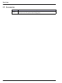
DETAILS DES MODIFICATIONS
DETAILS OF CHANGES
Version 00 :
15/04/2003
Evaluation initiale suivant les normes
EN 50014:1997 et EN 50020:2002.
Issue 00:
2003/04/15
Initial assessment according to EN 50014:1997
and EN 50020:2002
standards.

16
Specifications and Certifications
ATTESTATION D’EXAMEN UE DE TYPE - ANNEXE
EU TYPE EXAMINATION CERTIFICATE - SCHEDULE
Seul le texte en français peut engager la responsabilité du LCIE. Ce document ne peut être reproduit que dans son intégralité, sans aucune modification. Il est établi
en accord avec le
référentiel de certification ATEX du LCIE. The LCIE’s liability applies only on the French text.
This document may only be reproduced in its entirety
and without any change. It is issued in accordance with LCIE’s ATEX Certification Rules.
CERT-ATEX-FORM 04 Rev. 02 Page 4 / 4
1
Version
: 04
LCIE 03 ATEX 6003 X
Issue
: 04
Version 01 :
31/03/2004
Changement de raison sociale, Orbisphere SA
devient HACH ULTRA ANALYTICS
.
Issue 01:
2004/03/31
Change in name of the company, Orbisphere SA
becomes HACH ULTRA ANALYTICS.
Version 02 :
21/07/2009
- Changement de raison sociale en HACH
LANGE Sàrl.
-
Mise à jour normative suivant les normes
EN 60079-0:2006 et EN 60079-
11:2007.
-
Utilisation d’une sonde de type X1Y0E
-
Utilisation des piles TADIRAN SL 2770 ou
TL 5920.
-
Modifications de composants.
Issue 02:
2009/07/21
- Change in name of the company to HACH
LANGE Sàrl.
-
Normative update according to EN 60079-
0:2006 and EN 60079-
11:2007 standards.
- Use of type X1Y0E probe.
-
Use of TADIRAN batteries types SL 2770 or
TL 5920.
- Modifications of components.
Version 3 :
20/02/2013
Mise à jour normative suivant les normes
EN 60079
-0:2009 et EN 60079-11:2012.
Issue 03:
2013/02/20
Normative update according to
EN 60079
-0:2006 and EN 60079-11:2012.
Version 4 :
(actuelle)
- Les cartes numériques et analogiques
précédentes ont été fusionnées dans une
nouvelle
carte (numéro de pièce Hach
Lange: 1335C), les composants obsolètes
ont été remplacés.
-
Mise à jour normative suivant la norme
EN 60079-0:2012 + A11:2013.
-
Nouvelle plage de température ambiante :
0°C à +45°C.
-
L’appareil est alimenté uniquement par une
pile
SAFT LS 26500, les autres types
utilisés précédemment sont supprimés.
Issue 4:
(current
)
- Previous digital and analog boards have
been merged into one new board (Hach
Lange part number: 1335C), obsolete
components have been replaced.
-
Normative update according to
EN 60079-
0:20112 + A11:2013 standard.
-
New ambient temperature range: 0°C to
+45°C.
-
Apparatus is powered only by SAFT LS
26500 cell, other types previously used are
removed.

17
Section 3 Installation
This section provides necessary information to install and connect the instrument. Should you
have any questions, do not hesitate to contact your Hach representative regarding the
installation procedure.
The series 3650Ex Intrinsically Safe Portable Analyzer is a self-contained instrument configured
to make oxygen or hydrogen gas concentration measurements with Electrochemical (EC)
Sensors in a hazardous area, in either liquid or gaseous samples.
Refer to Instrument configurations on page 47 for a complete list of the instrument
configurations available.
Up to 500 measurement values can be stored in memory and downloaded to a personal
computer for further analysis.
The instrument is a portable unit and should be located convenient to the sample being
analyzed.
WARNING
Electrical danger and fire hazard. Only use the supplied power cable. Only qualified experts
may perform the tasks detailed in the installation section of this manual, while adhering to all
locally valid safety regulations.
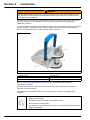
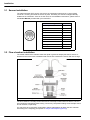
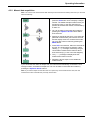
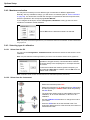
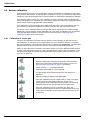
Figure 1 3650Ex instrument
1. Flow Chamber 4. Battery Cap
2. Electrochemical (EC) Sensor 5. Barometric Pressure Sensor Relief Valve
3. Pseudo RS-232 Port
• This instrument is powered by a special non-rechargeable Exproof lithium
battery (model 32960).
• The battery may be changed in the hazardous area.
• Do not short circuit the battery.
• The instrument can be connected to a PC via the Interface Box (model 29122)
only in a safe area.

18
Installation
3.1 Sensor installation
The electrochemical (EC) sensor connects to the instrument base through a 10-pin LEMO
connector. A locking nut holds the sensor in place. Generally, the sensor is shipped already
installed in the instrument. If this is not the case, for full installation instructions, please refer to
the Sensor Manual provided with your instrument.
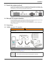
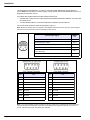
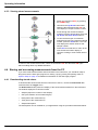
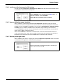
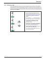
3.2 Flow chamber installation
The model 32007E flow chamber draws the liquid or gaseous sample past the EC sensor. It
attaches to the sensor with a threaded collar and is then sealed to the sensor with two O-rings.
The flow chamber’s centrally located inlet and eccentrically located outlet use either ¼-inch or
6-mm diameter transparent plastic tubing. Connect by compression fittings to the sample source
and to the drain, respectively.
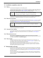
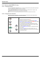
You may also have received a model 32051 sample tube adapter to attach the flow chamber
inlet tubing to the sampling point (Refer to Sample tube adapter (optional)).
Sensor Signal LEMO-10 Pin
Guard ring electrode Pin 1
Not used Pin 2
Temperature measurement Pin 3
Counter electrode Pin 4
Not used Pin 5
Temperature measurement Pin 6
Not used Pin 7
Not used Pin 8
Working electrode Pin 9
Not used Pin 10
Figure 2 3650Ex (rear view) with 32007E flow chamber
La page est en cours de chargement...
La page est en cours de chargement...
La page est en cours de chargement...
La page est en cours de chargement...
La page est en cours de chargement...
La page est en cours de chargement...
La page est en cours de chargement...
La page est en cours de chargement...
La page est en cours de chargement...
La page est en cours de chargement...
La page est en cours de chargement...
La page est en cours de chargement...
La page est en cours de chargement...
La page est en cours de chargement...
La page est en cours de chargement...
La page est en cours de chargement...
La page est en cours de chargement...
La page est en cours de chargement...
La page est en cours de chargement...
La page est en cours de chargement...
La page est en cours de chargement...
La page est en cours de chargement...
La page est en cours de chargement...
La page est en cours de chargement...
La page est en cours de chargement...
La page est en cours de chargement...
La page est en cours de chargement...
La page est en cours de chargement...
La page est en cours de chargement...
La page est en cours de chargement...
La page est en cours de chargement...
-
 1
1
-
 2
2
-
 3
3
-
 4
4
-
 5
5
-
 6
6
-
 7
7
-
 8
8
-
 9
9
-
 10
10
-
 11
11
-
 12
12
-
 13
13
-
 14
14
-
 15
15
-
 16
16
-
 17
17
-
 18
18
-
 19
19
-
 20
20
-
 21
21
-
 22
22
-
 23
23
-
 24
24
-
 25
25
-
 26
26
-
 27
27
-
 28
28
-
 29
29
-
 30
30
-
 31
31
-
 32
32
-
 33
33
-
 34
34
-
 35
35
-
 36
36
-
 37
37
-
 38
38
-
 39
39
-
 40
40
-
 41
41
-
 42
42
-
 43
43
-
 44
44
-
 45
45
-
 46
46
-
 47
47
-
 48
48
-
 49
49
-
 50
50
-
 51
51


Hach ORBISPHERE 3650 Atex Manuel utilisateur
- Catégorie
- Densitomètres
- Taper
- Manuel utilisateur
dans d''autres langues
Documents connexes
-
 Hach ORBISPHERE 3655 Manuel utilisateur
-
 Hach Lange ORBISPHERE 3100 Basic User Manual
-
 Hach Lange ORBISPHERE 3100 Basic User Manual
-
 Hach Polymetron 9582sc Basic User Manual
-
 Hach ORBISPHERE 3658 Basic User Manual
-
 Hach ORBISPHERE 3650 Atex Basic User Manual
-
 Hach ORBISPHERE K1200 Basic User Manual
-
 Hach ORBISPHERE 410 Basic User Manual
-
 Hach ORBISPHERE 366 Series Basic User Manual
-
 Hach polymetron 9240 Basic User Manual


Autres documents
-
Emerson FU40 Certificate
-
 Teledyne 317R Manuel utilisateur
-
YSI 51 Oxygen Meter Le manuel du propriétaire
-
Chemglass CG-9504-01 Le manuel du propriétaire
-
-
YSI 55 Oxygen Meter Le manuel du propriétaire
-
Ohaus MB23 Manuel utilisateur
-
Ohaus MB25 Manuel utilisateur
-
ABB ML82PH Operating Instructions Manual
-
MasterCool 69HVAC-PRO2 Mode d'emploi
