
Simplese
TM
NV-A4DS-UK
Installation Manual


1
ENGLISH
Danger
Exposure to extremely high noise levels may cause a permanent
hearing loss. Individuals vary considerably to noise induced hearing
loss but nearly everyone will lose some hearing if exposed to sufficiently
intense noise for a sufficient time. The U.S. Government's
Occupational Safety and Health Administration (OSHA) has specified
the following permissible noise level exposures:
According to OSHA, any exposure in the above permissible limits could
result in some hearing loss. Ear plugs or protectors in the ear canal or over
the ears must be worn when operating this amplification system in order to
prevent a permanent hearing loss. If exposure in excess of the limits as
put forth above, to insure against potentially harmful exposure to high
sound pressure levels, it is recommended that all persons exposed to
equipment capable of inducing high sound pressure levels, such as this
amplification system, be protected by hearing protectors while this unit is in
operation.
DURATION PER DAY (HOURS) 8 6 4 3 2 1
SOUND LEVEL (dB) 90 93 95 97 100 103
THIS SYMBOL IS INTENDED TO ALERT THE USER TO THE PRESENCE
OF NON-INSULATED "DANGEROUS VOLTAGE" WITHIN THE
PRODUCT'S ENCLOSURE THAT MAY BE OF SUFFICIENT MAGNITUDE
TO CONSTITUTE A RISK OF ELECTRIC SHOCK TO PERSONS.
THIS SYMBOL IS INTENDED TO ALERT THE USER TO THE PRESENCE
OF IMPORTANT OPERATING AND MAINTENANCE (SERVICING)
INSTRUCTIONS IN THE LITERATURE ACCOMPANYING THE UNIT.
1. Read all safety and operating instructions before using this
product.
2. All safety and operating instructions should be kept for future
reference.
3. Read and understand all warnings listed on the operating
instructions.
4 . Follow all operating instructions to operate this product.
5. This product should not be used near water, i.e. Bathtub,
sink,swimming pool, wet basement, etc.
6. Only use dry cloth to clean this product.
7. Do not block any ventilation openings, It should not be placed flat
against a wall or placed in a built-in enclosure that will impede the
flow of cooling air.
8. Do not install this product near any heat sources ;such
as,radiators, heat registers, stove or other apparatus (including
heat producing amplifiers) that produce heat.
9. Do not defeat the safety purpose of the polarized or grounding-
type plug. A polarized plug has two blades with one wider than the
0ther.A grounding-type plug has two blades and a third grounding
prong. The wide blade or the third prong are provided for your
safety If the provided plug does not fit into your outlet, consult an
electrician for replacement of the obsolete outlet.
10. Protect the power cord being walked on or pinched, particularly at
Plugs, convenience receptacles and the point where they exit
from the apparatus. Do not break the ground pin of the power
supply cord.
11 . Only use attachments specified by the manufacturer.
12. Use only with the cart, stand, tripod, bracket, or table specified by
the manufacturer or sold with the apparatus. When a cart is used,
use caution when moving cart/apparatus combination to avoid
injury from tip-over.
13. Unplug this apparatus during lightning storms or when unused for
long periods of time.
14. Care should be taken so that objects do not fall and liquids are
not spilled into the unit through the ventilation ports or any other
openings.
15. Refer all servicing to qualified service personnel. Servicing is
required when the apparatus has been damaged in any way;
such as, power-supply cord or plug is damaged, liquid has been
spilled or objects have fallen into the apparatus, the apparatus
has been exposed to rain or moisture, does not operate normally
or has been dropped.
16. WARNING: To reduce the risk of fire or electric shock, do not
expose this apparatus to rain or moisture.
IMPORTANT SAFETY INSTRUCTIONS
RISK OF ELECTRIC SHOCK
DO NOT OPEN
CAUTION: TO REDUCE THE RISK OF ELECTRIC SHOCK, DO
NOT REMOVE CHASSIS. NO USER-SERVICEABLE
PARTS INSIDE. REFER SERVICING TO QUALIFIED
SERVICE PERSONNEL.
AVIS: RISQUE DE CHOC ELECTRIQUE-NE PAS OUVRIR.
CAUTION
APPARATUS SHALL NOT BE EXPOSED TO DRIPPING OR SPLASHING
AND THAT NO OBJECTS FILLED WITH LIQUIDS, SUCH AS VASES,
SHALL BE PLACED ON THE APPARATUS.

2
FRENCH
DURE EN HEURES PAR JOUR 8 6 4 3 2 1
INIVEAU SONORE CONTINU EN dB 90 93 95 97 100 103
Danger
L‘exposition a des niveaux eleves de bruit peut provoquer une perte
permanente de l’audition, Chaque organisme humain reagit
differemment quant a la perte de l’audition, mais quasiment tout le
monde subit une diminution de I’acuite auditive lors d’une exposition
suffisamment longue au bruit intense. Les autorites competentes en
reglementation de bruit ont defini les expositions tolerees aux niveaux
de bruits:
Selon les autorites, toute exposition dans les limites citees ci-dessus,
peuvent provoquer certaines pertes d’audition. Des bouchons ou
protections dans l’appareil auditif ou sur l’oreille doivent etre portes lors
de l’utilisation de ce systeme d’amplification afin de prevenir le risque
de perte permanente de l’audition, Dans le cas d’expositions
superieures aux limites precitees il est recommande, afin de se
premunir contre les expositions aux pressions acoustiquese I evees
potentielIement dangeure u ses, aux personnes exposees aux
equipements capables de delivrer de telles puissances, tels ce
systeme d’amplification en fonctionnement, de proteger l’appareil
auditif.
ATTENTION: AFIN DE LlMlTER LE RISQUE DE CHO ELECTR/QUE, NE
PAS ENLEVER LE CHASSIS. NE CONTIENT PAS DE
PIECES POUVANT ETRE REPAREE PAR L’UTILISATEUR.
CONFER LE SERVICE APRES-VENTE AUX
REPARATEURS
ATTENTION
RISQUE DE CHOC ELECTRIQUE
NE PAS OUVRIR.
CE SYMBOLE A POUR BUT D'AVERTIR L'UTILISATEUR DE LA PRESENCE
DE VOLTAGE DANGEREUX NON-ISOLE A L'INTERIEUR DE CE PRODUIT
QUI PEUT ETRE DE PUISSANCE SUFFISAMMENT IMPORTANTE POUR
PROVOQUER UN CHOC ELECTRIQUE AUX PERSONNES.
CE SYMBOLE A POUR BUT D'AVERTIR L'UTILISATEUR DE LA PRESENCE
D'INSTRUCTIONS D'UTILISATION ET DE MAINTENANCE DANS LES
DOCUMENTS FOURNIS AVEC CE PRODUIT.
IMPORTANTES INSTRUCTIONS DE SECURITE
1. Lire avec attention toutes les recommandations et précautions
d'emploi avant d'utiliser ce produit.
2. Toutes les recommandations et précautions d'emploi doivent être
conservées afin de pouvoir s'y reporter si nécessaire.
3. Lire et comprendre tous les avertissements énumérés dans les
précautions d'emploi.
4. Suivre toutes les précautions d'emploi pour utiliser ce produit.
5. Ce produit ne doit pas être utilisé près d'eau, comme par exemple
baignoires, éviers, piscine, sous-sol humides ... Etc.
6. Utiliser exclusivement un chiffon sec pour nettoyer ce produit.
7. Ne bloquér aucune ouverture de ventilation. Ne pas placer le
produit tout contre un mur ou dans une enceinte fernée, cela
gênerait le flux d'air nécessaire au refroidissement.
8. Ne pas placer le produit près de toute source de chaeur telle que
radiateurs, arrivées d'air chaud, fourneaux ou autres appareils
générant de la chaleur (incluant les amplificateurs producteurs
de chaleur) .
9. Ne pas négliger la sécurité que procure un branchement polarisé
ou avec raccordement à la terre, Un branchement polarisé
comprend deux fiches dont l'une est plus large que l'autre. Un
branchement à la terre comprend deux fiches plus une troisième
reliée à la terre. Si la fiche secteur fournie ne s'insert pas dans
votre prise de courant. consulter un 'électricien afin de remplacer
votre prise obsolète.
10. Protéger le cordon d'alimentation de tout écrasement ou
pincement, particulièrement au niveau des fiches, des
réceptacles utilisés et à l'endroit de sortie de l'appareil. Ne pas
casser la fiche de terre du cordon d'alimentation.
11. Utiliser uniquement les accessoires spécifiés par le constructeur.
12. Utiliser uniquement avec le chariot de transport, le support, le
trépied, la console ou la table spécifiés par le constructeur ou
vendus avec l'appareil. Lors de l'utilisation d'un chariot, bouger
avec précaution l'ensemble chariotlappareil afin d'éviter les
dommages d'un renversement.
13 Débrancher cet appareil lors d'orages ou s'il n'est pas utilisé
pendant une longue période.
14. Des précautions doivent être prises afin qu'aucun objet ne tombe
et qu'aucun liquide ne se répande à l'intérieur de l'appareil par
les orifics de ventilation ou n'importe quelle autre ouverture.
15. Pour toutes interventions techniques s'adresser à un technicien
qualifié.L'intervention technique est nécessaire lorsque l'appareil
a été endommagé de n'importe quelle façon, comme par
exemple si le cordon secteur ou sa fiche sont détériorés,si du
liquide a coulé ou si des objets sont tombés à l'intérieur de
l'apparei1,si l'appareil a été exposé à la pluie ou à l'humidité, s'il
ne fonctionne pas normalement ou s'il est tombé.
16. ATTENTI0N:Pour réduire le risque d'incendie ou de choc
electrique ne pas exposer l'appareil à la pluie ou à l'humidité.
AFIN DE REDUIRE LES RISQUÉ D'INCENDIE ET DE DECHARGE
ELECTRIQUE, NE PAS EXPOSER CET APPAREIL A LA PLUIE OU A
L'HUMIDITE.

Table of Contents
Introduction Page 3
Wiring Diagram Page 4
Front Panel Features Page 5
Back Panel Features Page 5
Keypad Features Page 6
LRC Learning Remote Control Page 7
I. Prewire CAT5 Termination Page 8
II. Speaker Wire Termination Page 9
III. Allport Termination and Installation Page 9
IV. Installing the Simplese Amplifier Page 10
V. IR Outputs Page 10
VI. Keypad and Zone Setup Page 10
Zone EQ Control and Source Grouping Page 11
Volume Reset Page 11
All Off Page 11
Master Mode/All On Page 12
VII. Using the Fixed and Variable Lineouts Page 13
VIII. Using the Link Jack Page 14
IX. Mute Input Page 15
X. The LSA40 Local Source Amplifier Page 16
XI. The LSA40PD Power Distribution Hub Page 17
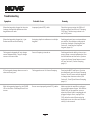
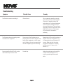
Troubleshooting Page 18
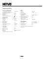
Specifications Page 20
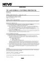
Addendum-NV-A4D Serial Control Protocol Page 21
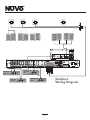
Installing the Simplese System in Your Home

3
Introduction
Congratulations on your purchase of the NuVo Simplese System. Simplese brings the best of today's digital technology to a true
whole-home audio system. Listening to multiple audio sources from independent zones throughout the home has never been
easier or more affordable.
The elegant UK® style keypads allow independent selection of up to four different audio sources from up to four zones in the
home. They are available in white and black to help match a variety of decorating choices. Generation D digital amplification
provides clear, precise digital sound to each zone without the heat generated by traditional analog amplification. The integrated
infrared repeater in each keypad means you can control all of your audio sources wirelessly from any zone of your home.
Enjoying quality audio throughout the home is simple and affordable with Simplese. This installation manual is designed to
provide a sequential, step-by-step guide to making full use of the many features and capabilities of the Simplese System.
Package Contents:
1 NV-A4D Four-Source, Four-Zone Amplifier
4 NV-A4DKP-UK UK style Zone Controller Keypads available in white or black
1 NV-LRC1 Universal Learning Remote Control
1 NV-A4DAP-UK UK style Allport™ Multi-port Connection Hub
1 NV-A4DAPC Allport Connection Cable
1 pr. NV-REM1U Single Space Rack Ear Mounts
4 NV-VEC IR emitters with feedback LED
4 NV-WP-UK UK style Wall Plates available in white or black

4
R
L
SENSITIVITY
OdBV = 1.0RMS
-12
+6
0
LEFT
+6
-12
RIGHT
0
AUDIO
INPUT
2
INPUT
OUTPUT
CONTROL
SPEAKER
MODEL NV-P2100
HIGH EFFICIENCY 200 WATT
STEREO AMPLIFIER
NuVo Technologies Cincinnati Ohio. USA
120V
60HZ
WATTS
250
UNIT
ON
+12VDC
100mA
VOLTAGE
TRIGGER
3-30 VOLTS
AC OR DC
ON/OFF SWITCH
AUDIO AC/DC
POWER
MODE
OUTPUT POWER
8 OHM: 70W X 2
4 OHM: 100W X 2
CONTROL
USE ONLY WITH 250V FUSE
Source 1
Tuner 1
Audio
Out
Source 2
Tuner 2
Audio
Out
Source 4
DVD
Audio
Out
Source 3
CD
Audio
Out
SOURCE INPUT
L
R
L
R
1
2
3
4
L
R
ZONE 4
FIXED
VAR
LINE OUT
IR OUT
1
3
2
4
SYSTEM
LINK
RS232
STATU S
ON=+5V
MUTE
=0V
SPEAKER AN D DATA SIGNALS
ALL PORT CO NNECTION
Simplese
CON FORMS T O
UL ST D.650 0
CER TIFIE D TO
CAN /CSA STD .E600 65
303 3118
C
US
R
T
E
E
T
K
N
I
C
M
NuVo Tec hnologi es Ci ncinnat i Ohi o USA
D
R
T
E
E
T
K
N
I
FOUR-SOURCE FOUR-Z ONE
100~24 0V 50 ~60Hz 85W
USE FOR SAT
OR CABLE
NORMAL
USE
56KHz38KHz
1
2
Simplese
Wiring Diagram
VOLUME
MUTE
MP3
SAT
HD
CD
VOLUME
MUTE
MP3
SAT
HD
CD
VOLUME
MUTE
MP3
SAT
HD
CD
VOLUME
MUTE
MP3
SAT
HD
CD

5
1
2
SOURCE INPUT
L
R
L
R
1
2
3
4
L
R
ZONE 4
FIXED
VAR
LINE OUT
IR OUT
1
3
2
4
SYSTEM
LINK
RS232
STATU S
ON=+12 V
MUTE
=0V
SPEAKER AND DATA SIGNA LS
ALL PORT CONN ECTION
Simplese
CON FORMS T O
UL ST D.65 00
CER TIFIE D TO
CAN /CSA STD .E600 65
303 3118
C
US
R
T
E
E
T
K
N
I
C
M
NuVo Tec hnologies Ci nci nnati Ohio USA
D
R
T
E
E
T
K
N
I
FOUR-SOURCE FOUR- ZONE
100~24 0V 50 ~60 Hz 85W
USE FOR SAT
OR CABLE
NORMAL
USE
56KHz38KHz
1
2
1
2
3
4
5
6
7
8
9
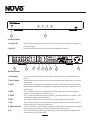
Front Panel Features
1. Stand-by LED This LED (light emitting diode) indicates, when lit, that the Simplese amplifier is plugged into
an AC power source.
2. Zone LED Each of these LEDs indicates, when lit, that its zone keypads are turned on.
Back Panel Features
1. Source Inputs Each of these stereo RCA inputs receives an audio signal from up to four independent audio
sources.
2. Zone 4 Lineouts These fixed and variable lineouts are used for attaching additional amplification to the zone 4
audio outputs.
3. IR OUT These outputs are designed to be used with the included IR (Infrared) emitters to transfer IR
function commands from the zone keypads to the appropriate audio source equipment; see IR
Outputs pg. 10.
4. MUTE This 3.5mm mono connection is designed to be used in conjunction with the NV-MI1 mute
interface; see Mute Input and the NV-MI1, pg. 15.
5. STATUS This 3.5mm mono connection provides a constant +5 volt output when a zone is turned on. This
can be used to trigger external equipment.
6. RS232 This is used for bidirectional serial control by third party home automation systems.
7. LINK This 3.5mm mono output is used to expand the Simplese System from four to eight zones; see
Using the Link Jack to Create Eight Zones, pg. 14.
8. Allport Connection This 25-pin terminal is used in conjunction with the Allport cable to integrate the zone keypads
and speakers into the system; see Allport Termination and Installation, pg. 9.
9. AC This is used with the included AC power cable to provide electrical power to the system when
attached to an active AC power outlet.

6
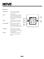
Keypad Features
1. Volume Level The level of the zone volume is
indicated by these LEDs (light
emitting diodes).
2. Power The power button turns that keypad's
zone on and off independently of the
other zones. Pressing and holding the
power button turns all the zones off
simultaneously.
3. Mute The mute button temporarily silences
any audio playing in that keypad's
zone.
4. Source Selection The source buttons independently
select any of the four sources
connected to the Simplese amplifier.
The selected source button will remain
lit.
5. IR Receiver Each keypad has an IR (infrared)
receiver located under the volume
button for wireless control of the audio
source equipment.
6. Volume Independent audio volume level for
each zone is controlled with these
buttons.
1
3
4
2
5
6
VOLUME
MUTE
MP3
SAT
HD
CD

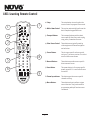
1. Setup: The setup button is used to place the
remote control in program/learn mode.
2. Whole-Home Control: This section automatically performs the
basic Simplese keypad functions.
3. Transport Buttons: The transport buttons perform basic
source specific functions, such as play,
stop, pause, forward and reverse.
4. Video Source Control: These buttons are typically used by
video equipment for menu navigation
and selection.
5. Source Volume: This is source specific volume control,
such as a TV or stereo receiver. This is not
used for NuVo zone volume.
6. Numeric Buttons: These buttons provide source specific
direct numeric access.
7. Power Button: This power button is for source specific
power on and off. It is not for NuVo zone
on and off.
8. Channel up and down: This button provides source specific
channel scrolling.
9. Macro Buttons: These buttons do not perform a given
source function. They can be used for
programming multiple function macro
commands.
1
2
3
4
5
6
MUTE
VOL-
VOL+
ON/OFF
H
O
M
E
C
O
N
T
R
L
E
-
O
L
H
O
W
S
O
UR
C
E
NV-LRC1
M1
M2
M3
M4
M6
M5
M7
M8
1
3
4
2
5
6
7
8
9
LRC1 Learning Remote Control
7

8
Installing the Simplese System in Your Home
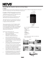
I. Prewire
The Simplese System uses CAT5 cable for keypad control and either two or four-conductor 16-gauge speaker wire. All the wire is
“homerun” from each zone to the location of the Allport connection hub.
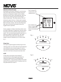
Complete CAT5 Crimping Instructions
The NuVo audio systems require CAT5, unshielded, twisted
pair (UTP), for communication between the
keypads/Display Pads and the main amplifier unit. Each
end of the wire is terminated with an RJ45 connector.
The Simplese System can accommodate 2000 total feet of
CAT5 cable. For the most reliable operation, it is best that
no single run of CAT5 exceeds 250 feet.
The correct wiring scheme for the CAT5 cable is standard
EIA/TIA 568A. Properly terminating the CAT5 cable is
crucial for the operation of the system. It is very important
to use a good quality crimp tool, and testing each end to
end run with a CAT5 wire tester will insure that your
system operates flawlessly, fig.1.
Step-by-Step Crimping Instructions
1. Strip a 2 to 3 inch portion of the insulation,
exposing the 4 twisted pairs.
2. Untwist the wires and fan them out
individually. Arrange the wires into the
correct color scheme as shown in Fig. 1.
3. Flatten the wires in their correct order, and trim
them evenly across the top. Most crimp tools have
a wire trimmer built-in. It is best to trim the wires
to about ½” in length.
4. While holding the wires flat between your thumb
and forefinger, insert the wires into the RJ45
connector, so each is in its own slot. Push the wire
into the RJ45, so all 8 conductors touch the end of
the connector. The insulation jacket should
extend beyond the crimp point of the RJ45.
5. Insert the RJ45 into the crimp tool receptacle and
squeeze the tool firmly. Note that a ratchet type
tool should tighten down until it no longer clicks.
6. The RJ45 should be firmly crimped to the CAT5
insulation. It is necessary that the color scheme
be repeated identically on each end of the wire.
Fig. 1: EIA 568A wiring scheme for CAT5 Cable
Pin #
1. Green Stripe
2. Green
3. Orange Stripe
4. Blue
5. Blue Stripe
6. Orange
7. Brown Stripe
8. Brown
Note: Colors listed as “stripe” are a white wire
with a colored stripe.
Step 1 Step 2 Step 3
Step 4 Step 5 Step 6
1 2 3 4 5 6 7 8
Top view with
tab down.
Wires insert from
this end.
Pair 2
Pair 3
Pair 4
Pair 1
I
R
S
i
gn
a
l
-
So
u
r
c
e
1
G
rou
nd
Contr
ol
Dat
a Bu
s
-
C
ont
r
o
l
D
a
t
a
Bus
+
I
R S
ignal
-
S
o
u
r
c
e
2
G
r
o
und
+
12
V
P
ow
e
r
G
r
o
un
d

9
II. Speaker Wire Termination
It is important to keep the proper orientation of
positive and negative signal for each speaker
connection. Typically, two-conductor speaker wire uses
red to denote positive and black to denote negative.
Some types of wire indicate positive with a dark line
running through the insulation. Four-conductor wire
can also be used. This has four separate wires in one
outer jacket, making it possible to run a single speaker
wire to a zone for its pair of speakers. This type of wire
typically uses red and black for one speaker and white
as positive and green as negative for the second
speaker.
Note: The Simplese System is designed to handle one
pair of 8-ohm speakers per zone. Using more than one
pair of speakers per zone could cause damage to the
amplifier output.
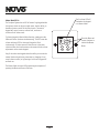
III. Allport Termination and Installation
Both the speaker wire and CAT5 cables for each zone
terminate into the back side of the Allport. The order of
CAT5 plug-ins is irrelevant to the operation of the
system, but it is recommended that you label the
individual CAT5 cables for future reference. Follow the
zone and polarity labeling for the speaker wire
termination, fig. 2.
The final connection from the Allport is made with the
Allport cable supplied with the Simplese System, fig. 3.
Fig. 3
Fig. 2
SYSTEM
LINK
RS232
STATU S
ON=+1 2V
MUTE
=0V
SPEAKER AND DATA SIGNALS
ALL PORT CONNECTION
Simplese
CONFOR MS TO
UL ST D.6500
CERTIF IED TO
CAN/CS A STD.E600 65
3033118
C
US
R
T
E
E
T
K
N
I
C
M
NuVo Tec hnologie s Cincinnati Oh io USA
D
R
T
E
E
T
K
N
I
FOUR-SOURCE FOUR-ZONE
100~2 40V 50~60Hz 85W
SYSTEM

10
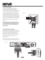
IV. Installing the Simplese Amplifier
The Simplese amplifier component is designed to be
placed on a shelf or in a component rack. Rack ear
mounts are supplied with the system. If you are
using the rack ears and mounting the amplifier with
other components, you should remove the feet.
Remove the two screws at the front of each side of
the lid and use the longer screws included with the
rack ears to attach the ears to the Simplese
amplifier.
The audio sources are plugged into the four source
inputs on the back panel of the Simplese amplifier
using stereo RCA cables, fig. 4.
V. IR Outputs
The Simplese System ships with four IR emitters for
transferring IR data from the keypad receivers
(located under the volume button) to the IR receiver
on each piece of source equipment. There are two
separate IR output sections on the back panel. The
38Khz outputs are used for most audio sources. The
exception to this is cable and satellite boxes, which
operate at a higher IR carrier frequency closer to
56Khz. A second source one and two 56Khz output is
available for these devices. It is important that the
output being used for each source matches the
source input number. The outputs work individually
with each source to allow independent source
control. Simply plug the emitter into the appropriate
IR output on the back of the Simplese amplifier and
attach the flasher end over the IR receiver of the
source equipment, fig. 5.
VI. Keypad and Zone Setup
Each keypad requires a specific zone setting to
establish the keypad's location. This setting is made
on the back of the keypad using an eight-position
rotary switch. To set the switch, place a small slot-
head screwdriver in the slot in the switch and turn it
clockwise to the appropriate zone number 1-4, fig.
6. The remaining switch positions, 5-8, allow for an
additional keypad in each zone. Position 5
corresponds to zone 1, 6 to zone 2, 7 to zone 3, and 8
to zone 4. The additional letters do not apply to
Simplese. Note that the Allport only has four RJ45
jacks, so additional keypads require the use of a
CAT5 splitter.
Fig. 4
Fig. 5
Fig. 6
SOURC E INPUT
L
R
L
R
1
2
3
4
L
R
ZONE 4
FIX ED
VAR
LINE OU T
Source 1
Tuner 1
Audio
Out
SOURCE INPUT
L
R
L
R
1
2
3
4
L
R
ZONE 4
FIXED
VAR
LINE OUT
IR OUT
1
3
2
4
USE FOR SAT
OR CABLE
NORMAL
USE
56KHz38KHz
1
2
Network
Zone
Address
Connection
Use only with
NuVo Simplese System
WARNING:
AVIS:
Utiliser uniquement avec
NuVo Simplese System
NuVo Technologies LLC Hebron, Kentucky USA
www.nuvtoechnologies.com
Local Source
Simplese Keypad
Model NV-A4DKP-UK
0
1
2
F
3
E
4
D
5
C
6
7
B
8
A
9

11
EQ Control and Source Grouping
The keypads can be used to set specific zone functions.
These are for bass and treble EQ response and source
grouping. To change bass response, press the Mute
button and Source 1 button simultaneously. Adjust the
bass level up or down by using the Volume Up and
Volume Down buttons. The volume indicator LEDs will
indicate the output level, fig. 7. Adjust treble response
using the same process. This is accessed by pressing the
Mute and Source 2 buttons. Once the desired setting is
made, press the Source button again to return the
keypad to normal operation.
Source grouping is a feature that allows multiple zones
in an open living space to always share the same source
selection but still retain individual volume and on/off
control. This is achieved by pressing Mute and Source 3.
Volume Up enables the group function, and Volume
Down disables the group function and causes the
keypad to operate independently of all other groups,
fig. 8.
Volume Reset
The Simplese System keypads automatically reset the
listening volume to a low level when all zones have been
turned off and a zone is turned on again. If a zone is
turned off and turned back on before all the zones are
turned off, it will return at the previous volume level.
All Off
All the zones in the system can be turned off
simultaneously from any keypad by pushing and
holding the power button until the keypad goes
completely dark. A single push and release of the power
button will only turn that zone off. If another zone is on,
the power button will remain lit.
Fig. 7
Fig. 8
Press the Mute and
Source 1 for bass
control and Mute and
Source 2 for treble
control.
The lit volume LED
indicates the treble
and bass levels.
VOLUME
MUTE
MP3
SAT
HD
CD
VOLUME
Group Disabled Group Enabled
VOLUME
FLAT
-4 dB
+4 dB
+6 dB
+8 dB
-6 dB
-8 dB

12
Master Mode/All On
The Simplese System has an All On feature. Any keypad within
the system, which can be up to eight zones, has the ability to
become a master control for the entire house. The master
keypad will control zone on, volume level, and source
selection for all other zones.
To place a keypad in Master Mode function, simply press the
Mute and Source 4 buttons simultaneously. This will cause the
volume indicator LED for that zone’s keypad to flash
continuously. All other zones will then turn on to the same
relative volume level and increase or decrease with the volume
adjustment on the master keypad.
Any of the other zone keypads have the ability to override the
master function by selecting a new source, changing a local
zone’s volume control, or by turning a local zone’s keypad off
and back on.
The Master Mode is turned off by repeating the sequence of
pressing the Mute and Source 4 buttons.
Press the Mute and
Source 4 buttons to
initiate the Master
Mode.
The lit volume LED will
flash when the keypad
is in Master Mode.
VOLUME
MUTE
MP3
SAT
HD
CD

13
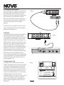
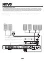
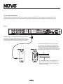
VII. Using the fixed and Variable Lineouts
Zone 4 is equipped with two types of pre-amp lineouts for use with an additional amplifier. This can be dedicated to an outdoor
zone or large living area that would benefit from more than one pair of speakers. NuVo manufactures a 200-watt stereo amplifier
specifically designed for this purpose, called the NuVo P2100, although any audio amplifier can be used with the lineouts. The
examples shown in this manual refer specifically to the P2100.
The variable lineout is intended for use in a zone where you want the Simplese keypads to control the volume output of the
external amplifier, fig. 9.
Fig. 9
SOURCE INPUT
L
R
L
R
1
2
3
4
L
R
ZONE 4
FIXED
VAR
LINE OUT
IR OUT
1
3
2
4
SYSTEM
LINK
RS232
STATU S
ON=+5V
MUTE
=0V
SPEAKER AND DATA SIGNA LS
ALL PORT CONN ECTION
Simplese
CON FORMS T O
UL ST D.65 00
CER TIFIE D TO
CAN /CSA STD .E600 65
303 3118
C
US
R
T
E
E
T
K
N
I
C
M
NuVo Tec hnologies Ci nci nnati Ohio USA
D
R
T
E
E
T
K
N
I
FOUR-SOURCE FOUR- ZONE
100~24 0V 50 ~60 Hz 85W
USE FOR SAT
OR CABLE
NORMAL
USE
56KHz38KHz
1
2
R
L
SENSITIVITY
OdBV = 1.0RMS
-12
+6
0
LEFT
+6
-12
RIGHT
0
AUDIO
INPUT
2
INPUT
OUTPUT
CONTROL
SPEAKER
MODEL NV-P2100
HIGH EFFICIENCY 200 WATT
STEREO AMPLIFIER
NuVo Technologies Cincinnati Ohio. USA
120V
60HZ
WATTS
250
UNIT
ON
+12VDC
100mA
VOLTAGE
TRIGGER
3-30 VOLTS
AC OR DC
ON/OFF SWITCH
AUDIO AC/DC
POWER
MODE
OUTPUT POWER
8 OHM: 70W X 2
4 OHM: 100W X 2
CONTROL
USE ONLY WITH 250V FUSE
The Zone 4 keypad controls the audio volume.
Diagram shown using the NuVo P2100 amplifier
VOLUME
MUTE
MP3
SAT
HD
CD

Fig. 10
The fixed lineout can be used for zones where it is more appropriate to have a separate volume control from the NuVo keypad for
the external amplifier, fig. 10. A good example of this use would be an outdoor zone that is being used in conjunction with zone 4.
All three versions, zone 4 amplified output, variable lineout, and fixed lineout can be used simultaneously.
14
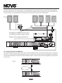
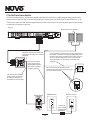
VIII. Using the Link Jack to Create Eight Zones
Two separate Simplese Systems can be made to react as one using the back-panel 3.5mm connection labeled LINK. This requires
the use of “Y” cables to link the source inputs and IR outputs. A single stereo mini-patch cable is then plugged into the LINK jack
on both Simplese amplifiers. This links the All Off command so when it is initiated at any of the zone keypads, all eight zones will
turn off, fig. 11
Fig. 11
SOURCE INPUT
L
R
L
R
1
2
3
4
L
R
ZONE 4
FIXED
VAR
LINE OUT
IR OUT
1
3
2
4
SYSTEM
LINK
RS232
STATU S
ON=+5V
MUTE
=0V
SPEAK ER AN D DATA SIG NALS
ALL PORT CONNECTION
Simplese
CON FORMS T O
UL ST D.650 0
CER TIFIE D TO
CAN /CSA STD .E600 65
303 3118
C
US
R
T
E
E
T
K
N
I
C
M
NuVo Tec hnol ogi es Cincin nati Ohio U SA
D
R
T
E
E
T
K
N
I
FOUR-SOURCE FOUR-Z ONE
100~24 0V 50~60H z 85W
USE FOR SAT
OR CABLE
NORMAL
USE
56KHz38KHz
1
2
R
L
SENSITIVITY
OdBV = 1.0RMS
-12
+6
0
LEFT
+6
-12
RIGHT
0
AUDIO
INPUT
2
INPUT
OUTPUT
CONTROL
SPEAKER
MODEL NV-P2100
HIGH EFFICIENCY 200 WATT
STEREO AMPLIFIER
NuVo Technologies Cincinnati Ohio. USA
120V
60HZ
WATTS
250
UNIT
ON
+12VDC
100mA
VOLTAGE
TRIGGER
3-30 VOLTS
AC OR DC
ON/OFF SWITCH
AUDIO AC/DC
POWER
MODE
OUTPUT POWER
8 OHM: 70W X 2
4 OHM: 100W X 2
CONTROL
USE ONLY WITH 250V FUSE
The additional speakers from zone 4 are
controlled by a separate volume control.
Diagram shown using the NuVo P2100
IR OUT
IR OUT
1
1
3
3
2
2
4
4
SYSTEM
SYSTEM
LINK
LINK
RS232
RS232
STATU S
ON=+12 V
STATU S
ON=+12 V
MUTE
=0V
MUTE
=0V
SPEAK ER AND DATA SIGNAL S
SPEAK ER AND DATA SIGNAL S
ALL POR T CONNECTION
ALL POR T CONNECTION
Simplese
Simplese
USE FOR SAT
OR CABLE
USE FOR SAT
OR CABLE
NORMAL
USE
NORMAL
USE
56KHz
56KHz
38KHz
38KHz
1
1
2
2
VOLUME
MUTE
MP3
SAT
HD
CD

15
IX. Mute Input and the NuVo MI1
The back panel of the Simplese amplifier has a 3.5mm mono input labeled MUTE. This is designed to be used with the NuVo
MI1 Mute Interface. When the MI1 is connected, the system will temporarily mute when the phone or doorbell rings, fig. 12.
Fig. 12
MUTE INTERFACE
ADAPTER
NV-MI1
CONNECT TO
MUTE INPUT
A
B
A
B
DOORBELL 1
DOORBELL 2
Connect to Telephone RJ-11
Line 1: Pins 3,4 Line 2: Pins 2,5
Model NV-MI1
Mute Interface Module
The MI1 connects to the NuVo amplifier using a standard
mono patch cable with a mini-plug on each end. Plug one
end into the EXT. MUTE input on the back of the amplifier
and the other end into the input on the front of the MI1.
The back of the MI1 will accept up to two AC or
DC voltages from two different doorbell chimes.
This connection is done with two conductor wire
from the terminals on the doorbell chime to the
Doorbell A or Doorbell B inputs on the back of the
MI1. Polarity is not important for this connection.
Up to two phone lines can be brought into the
RJ-11 connection on the back of the MI1. The
voltage from the phone ringer will trigger the
NuVo System to mute.
SOURCE INPUT
L
R
L
R
1
2
3
4
L
R
ZONE 4
FIXED
VAR
LINE OUT
IR OUT
1
3
2
4
SYSTEM
LINK
RS232
STATU S
ON=+12 V
MUTE
=0V
SPEAKER AND DATA SIGNA LS
ALL PORT CONN ECTION
Simplese
CON FORMS T O
UL ST D.65 00
CER TIFIE D TO
CAN /CSA STD .E600 65
303 3118
C
US
R
T
E
E
T
K
N
I
C
M
NuVo Tec hnologies Ci nci nnati Ohio USA
D
R
T
E
E
T
K
N
I
FOUR-SOURCE FOUR- ZONE
100~24 0V 50 ~60 Hz 85W
USE FOR SAT
OR CABLE
NORMAL
USE
56KHz38KHz
1
2

X. The LSA40 Local Source Amplifier
The LSA40 is highly versatile , 40 watt stereo amplifier designed to be installed in a single gang low voltage ring. An audio
sensing feature allows the LSA40 to automatically amplify any incoming line-level audio signal. As described in fig. 13, the
LSA40 can be connected to the Simplese keypad allowing use with a local source or an incoming NuVo system source through
a common pair of speakers in any zone.
R
R
+
+
The connection from the LSA40 to the
Simplese keypads is done using a green two
pin screw down terminal.
A two conductor wire is used as a voltage trigger from
the LSA40 to the NuVo zone keypad. When the zone is
turned on this allows to NuVo system audio to pass to
the zone speakers. When the zone is turned off the
internal amplifier of the LSA40 is automatically
engaged.
SOURCE INPUT
L
R
L
R
1
2
3
4
L
R
ZON E 4
FIX ED
VAR
LINE OUT
IR OUT
1
3
2
4
SYSTEM
LIN K
RS2 32
STATUS
ON= +12V
MUT E
=0V
SPEAKE R AND DATA SIGNAL S
ALL PORT C ONN ECT ION
Simplese
CONF ORMS TO
UL STD .6500
CERT IFIED T O
CAN/ CSA STD. E6006 5
3033 118
C
US
R
T
E
E
T
K
N
I
C
M
NuVo Tec hnolo gies Ci ncinn ati Ohi o USA
D
R
T
E
E
T
K
N
I
FOUR-SOURCE FOUR-ZONE
100 ~240V 5 0~60H z 85W
USE F OR SAT
OR CA BLE
NOR MAL
USE
56K Hz38K Hz
1
2
The selected zone speaker
output of the “Generation
D” Simplese Allport™ is
wired directly to the LSA40.
INPUT
POWER
LSA40 Back
LSA40 Front
AC Power Source
Any stereo line level
source signal can be
amplified through the
local source speakers
using the LSA40.
50 Watt AC
power adapter
supplied with
the LSA40S
NuVo System zone speakers.
Any NuVo System zone output can
be wired to the LSA40 Local Source
Amplifier.
+
+
-
-
L
L
L
L
R
R
+
+
-
-
-
-
MODEL:NV-LSA40
LOCAL SOURCE AMPLIFIER
28
VDC
T
O
K
E
Y
P
A
D
1
.
5
A
TO
A
M
P
L
I
F
I
ER
TO SP
E
AKER
WIRE STRIP 5/16” (8MM)
Designed In USA
Made In China
NuVo Technologies LLC Cincinnati, Ohio USA
www.nuvotechnologies.com
NV-LSA40
Local Source Amplifier
Fig. 13
16
VOLUME
MUTE
MP3
SAT
HD
CD

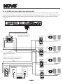
XIV. NV-LSA40PD Local Source Amplifier Power Distribution Hub
The LSA40PD is a great device for distributing the necessary DC power to up to 4 individual LSA40 amplifiers. This allows the LSA40
components to be remotely located without the need for an external power supply in the zone, fig. 14. The LSA40PD is typically located
where the Simplese amplifier is installed. The power from the head end to each of LSA40 locations is sent over standard 16 gauge
speaker wire.
+
+
-
-
L
L
L
L
R
R
R
R
+
+
+
+
-
-
-
-
MODEL:NV-LSA40
LOCAL SOURCE AMPLIFIER
2
8
V
D
C
T
O
K
E
YP
AD
1
.5A
TO
A
M
P
LIF
I
E
R
TO
SP
E
AKE
R
WIRE STRIP 5/16” (8MM)
Designed In USA
Made In China
NuVo Technologies LLC Cincinnati, Ohio USA
www.nuvotechnologies.com
+
+
-
-
L
L
L
L
R
R
R
R
+
+
+
+
-
-
-
-
MODEL:NV-LSA40
LOCAL SOURCE AMPLIFIER
2
8
V
D
C
T
O
K
EY
P
A
D
1
.
5
A
T
O
A
M
P
LIF
I
E
R
T
O
S
P
E
AK
E
R
WIRE STRIP 5/16” (8MM)
Designed In USA
Made In China
NuVo Technologies LLC Cincinnati, Ohio USA
www.nuvotechnologies.com
+
+
-
-
L
L
L
L
R
R
R
R
+
+
+
+
-
-
-
-
MODEL:NV-LSA40
LOCAL SOURCE AMPLIFIER
2
8
VD
C
T
O
K
EYP
A
D
1
.
5
A
T
O
A
M
P
L
I
F
I
E
R
T
O
S
PE
A
K
E
R
WIRE STRIP 5/16” (8MM)
Designed In USA
Made In China
NuVo Technologies LLC Cincinnati, Ohio USA
www.nuvotechnologies.com
+
+
-
-
L
L
L
L
R
R
R
R
+
+
+
+
-
-
-
-
MODEL:NV-LSA40
LOCAL SOURCE AMPLIFIER
2
8
V
D
C
T
O
KEY
P
AD
1.5A
T
O
A
M
P
L
I
F
I
E
R
T
O
SP
E
A
K
ER
WIRE STRIP 5/16” (8MM)
Designed In USA
Made In China
NuVo Technologies LLC Cincinnati, Ohio USA
www.nuvotechnologies.com
+
-
+
-
MODEL:NV-LSA40PD-DC
LOCAL SOURCE AMPLIFIER
DESIGNED IN USA
28VDC 5A
ZONE 1
MADE IN CHINA
R
T
E
T
E
K
I
N
3033118
R
T
E
E
T
K
N
I
CM
ZONE 3
+
-
+
-
ZONE 2 ZONE 4
POWER
LSA40PD Front
LSA40PD
Back
200 Watt AC
power adapter
included with
the LSA40PD
AC Power Source
LSA40 Back
LSA40 Back
LSA40 Back
LSA40 Back
D
16 gauge 2 conductor speaker wire is required to send
voltage from the LSA40PD to four separate zones.
Any NuVo System zone output can
be wired to the LSA40 Local Source
Amplifier.
The Allport receives the speaker
and CAT5 wires from each zone and
connects them to the Simplese
SOURCE INPUT
L
R
L
R
1
2
3
4
L
R
ZON E 4
FIX ED
VAR
LINE OUT
IR OUT
1
3
2
4
SYSTEM
LIN K
RS2 32
STATUS
ON= +12V
MUT E
=0V
SPEAKE R AND DATA SIGNAL S
ALL PORT C ONN ECT ION
Simplese
CONF ORMS TO
UL STD .6500
CERT IFIED T O
CAN/ CSA STD. E6006 5
3033 118
C
US
R
T
E
E
T
K
N
I
C
M
NuVo Tec hnolo gies Ci ncinn ati Ohi o USA
D
R
T
E
E
T
K
N
I
FOUR-SOURCE FOUR-ZONE
100 ~240V 5 0~60H z 85W
USE F OR SAT
OR CA BLE
NOR MAL
USE
56K Hz38K Hz
1
2
17
Fig. 14
VOLUME
MUTE
MP3
SAT
HD
CD
VOLUME
MUTE
MP3
SAT
HD
CD
VOLUME
MUTE
MP3
SAT
HD
CD
VOLUME
MUTE
MP3
SAT
HD
CD
La page est en cours de chargement...
La page est en cours de chargement...
La page est en cours de chargement...
La page est en cours de chargement...
La page est en cours de chargement...
La page est en cours de chargement...
La page est en cours de chargement...
La page est en cours de chargement...
La page est en cours de chargement...
-
 1
1
-
 2
2
-
 3
3
-
 4
4
-
 5
5
-
 6
6
-
 7
7
-
 8
8
-
 9
9
-
 10
10
-
 11
11
-
 12
12
-
 13
13
-
 14
14
-
 15
15
-
 16
16
-
 17
17
-
 18
18
-
 19
19
-
 20
20
-
 21
21
-
 22
22
-
 23
23
-
 24
24
-
 25
25
-
 26
26
-
 27
27
-
 28
28
-
 29
29


Nuvo Simplese NV-A4DS-UK Manuel utilisateur
- Taper
- Manuel utilisateur
- Ce manuel convient également à
dans d''autres langues
- English: Nuvo Simplese NV-A4DS-UK User manual
Documents connexes
-
Nuvo NV-VEC Guide d'installation
-
-
-
Nuvo Essentia BTicino NV-E6DXS-BT Guide d'installation
-
-
-
-
-
-
