ADEMCO TeleSmart Installation And Setup Manual
- Taper
- Installation And Setup Manual

®
K3950V2 3/2/01 (bx)
,QVWDOODWLRQDQG6HWXS*XLGH

– 2 –
7DEOHRI&RQWHQWV
Introduction.......................................................................................................................3
Features....................................................................................................................................................... 3
Mounting the Module................................................................................................................................. 3
Wiring Connections ..........................................................................................................4
Programming the System .................................................................................................6
Programming Overview.............................................................................................................................. 6
Programming Steps..................................................................................................................................... 7
Downloading .............................................................................................................................................. 8
Regulatory Agency Statements........................................................................................9
6SHFLILFDWLRQV
Size: 3-7/8” W x 7” H x 1-3/8” D
(98mm x 178mm x 35mm)
Voltage: 10.5VDC-14.5VDC
Current: Standby: 84mA (not including connected keypads)
“Speaking” at keypad: 116mA (vol lo); 124mA (vol med); 133mA
(vol hi)
“Speaking” at speaker: 165mA (vol lo); 229mA (vol med); 267mA
(vol hi)
“Speaking” at keypad & speaker: 346mA max. (volume hi)
Operating Temp.: 32° to 122° F (0° to 50° C)
Storage Temp.: – 40° to 158° F (– 40° to 70° C)
Maximum 20 minutes, including messages, memos, and all voice tags
Recording Time: 2 minute maximum per message
Caller ID Log: Stores up to 50 call entries, 51st entry overwrites oldest call, etc.
Max. Messages: Stores approximately 63 messages (saved and new)
Keypads: 6162, 6139T
FCC ID: AC3USA-34957-TX-T
REN: 0.6B

– 3 –
,QWURGXFWLRQ
This guide provides information for installing and programming the TeleSMART system.
TeleSMART works in conjunction with the following control panels and keypads:
Controls: VISTA-10SE, VISTA-20SE*, VISTA-50P*
*when used in single-partition installations only
Keypads: 6162, 6139T (controls TeleSMART
†
and security system functions)
†
To access TeleSMART features, these keypads must be connected to the
TeleSMART module. Keypads used only for security system functions should be
connected to the security system’s keypad terminals.
)HDWXUHV
The TeleSMART system provides a voice interface for an ADEMCO security system and the
TeleSMART phone system. It has the following features:
•
4 unique mailboxes for storing messages
•
6 user access codes
•
Security system interface
•
Memo feature for leaving messages for other users
•
Caller ID capabilities for up to 25 phone numbers
•
Memory (speed) dialing for up to 15 phone numbers
•
Repeat dialing (automatically redial busy numbers)
•
Last number redial
•
Call screening (with and without Caller ID)
•
Privacy (turn off the ringer)
•
Remote access of TeleSMART and security system
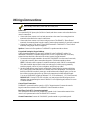
0RXQWLQJWKH0RGXOH
The TeleSMART Module should be mounted in the security system’s control cabinet if space is
available, or within a grounded metal enclosure to provide proper ESD protection.
Mounting Inside the Use double-sided tape to attach the module to the interior surface
Control’s Cabinet: of the cabinet, or hang it on two screws. Do not mount it on the cabinet door
or attach it to the control’s PC board.
Mounting Outside Use the screw holes at the rear of the module. Wires can be
the Cabinet: brought out from the side or back (use the round breakout on the back).
Affix the supplied Summary of Connections label to the module’s inside cover or to the inside of
the cabinet door.

– 4 –
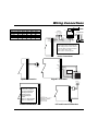
:LULQJ&RQQHFWLRQV
Before making connections, power down the control panel.
Phone Line
Use a standard RJ31X phone jack (CA38A in Canada) and direct-connect cord as described in the
control’s instructions.
1. Connect the direct-connect cord’s red and green wires to the control’s incoming phone line
terminals as described in the control’s instructions.
2. Connect the direct-connect cord’s brown and gray wires to TeleSMART’s “Home Phones”
terminals, disconnecting them from the control’s premises phone terminals, if previously connected.
3. Connect the control’s local phone TIP and RING terminals to TeleSMART’s “From Control”
terminals, using jumper wires (not supplied).
Speaker: Connect an 8 Ohm speaker to TeleSMART’s speaker terminals as shown.
Keypad and Setting the Keypad Address
Connect keypads intended to be used with TeleSMART to the TeleSMART module. Use
addressable, TeleSMART compatible keypads (6162, 6139T). Keypads used only for security
system functions should be connected to the security system’s keypad terminals.
1. Disconnect those keypads intended to be used with TeleSMART from the control’s terminals,
if previously connected, then connect these keypads to TeleSmart terminals as shown.
NOTE: Run audio cable in separate 2-conductor twisted-pair cable (22AWG recommended).
This cable should be kept at least 6 inches from other types of cables carrying potentially
interfering signals, such as AC power, telephone, and polling loop cables.
2. Set the keypad address, tamper option, and playback volume setting by pressing and holding
the [1] and [3] keys at the same time for 3 seconds, then follow the prompts. You must press
these keys within 60 seconds of power-up to set the address and/or tamper option; you can set
the volume at any time after power-up. Refer to the instructions included with the keypad..
You can set TeleSMART keypads to addresses 2-22, 25-30 (addresses 0, 1, 23, 24 are reserved).
IMPORTANT: If using VISTA-50P or higher, you must program the following two device
addresses when programming the control: address 23 = set as alpha keypad; address 24 = set as
TeleSmart Module.
Control Panel Connections
TeleSMART is powered from the control’s +12VDC keypad terminal. Connect the control’s
keypad connection terminals to the TeleSMART Control terminals as shown.
Real-Time Clock (RTC) Connection (optional)
This connection is used to drive the TeleSMART internal clock. Connect either terminal of the
control’s AC input terminals to the TeleSMART RTC terminal.
Ground Connections: Connect the TeleSMART ground terminal to a good earth ground.

– 5 –
:LULQJ&RQQHFWLRQV
TYPICAL
CONTROL’S
PHONE TERMINALS
LOCAL INCOMING
RING
TIP
RING
TIP
RED
GREEN
BROWN
GREY
DIRECT
CONNECT
CORD
1
2
3
4
5
6
7
8
9
10
11
12
13
14
15
16
17
18
RJ31X
1
2
3
45
6
7
8
RING
TIP
INCOMING
PHONE LINE
TO
PREMISES PHONES
GREENRED
GREY
BROWN
RING
TIP
FROM
CONTROL
HOME
PHONES
phon_conn-V0
Phone Connections
8 ohm Speaker
1
2
3
4
5
6
7
8
9
10
11
12
13
14
15
16
17
18
AUX
SPEAKER
IN
OUT
GRN (DATA IN)
RED (+12VDC)
BLACK (–)
YEL (DATA OUT)
USE OUTER
WIRES OF
AUDIO CABLE
AUDIO IN
1
2
3
4
5
6
7
8
9
10
11
12
13
14
15
16
17
18
KEYPADS
KEYPAD
AUDIO
BUS
®
1
OFF
4
MAX
7
INSTANT
READY
2
AWAY
5
TEST
8
CODE
0
3
STAY
6
BYPASS
9
CHIME
#
ARMED
READY
MESSAGE
Speaker Connection Keypad Connections
1
2
3
4
5
6
7
8
9
10
11
12
13
14
15
16
17
18
YEL (DATA OUT)
RED (+12VDC)
GRN (DATA IN)
BLACK (-) GND
TO CONTROL'S
KEYPAD
TERMINALS
REAL-TIME CLOCK (RTC)
1
2
3
4
5
6
7
8
9
10
11
12
13
14
15
16
17
18
EARTH
GROUND
TYPICAL
CONTROL'S
AC TERMINALS
Control Connections RTC and Ground Connections
WIRE RUN LENGTHS
Wire Gauge 150mA 300mA 500mA 600mA 750mA
22 AWG 160 ft 80 ft 50 ft 42 ft 32 ft
20 AWG 260 ft 130 ft 80 ft 67 ft 52 ft
18 AWG 410 ft 220 ft 130 ft 115 ft 83 ft
16 AWG 650 ft 330 ft 200 ft 170 ft 130 ft
IMPORTANT:
If using
VISTA-50P or higher,
you must program the
following two device
addresses when
programming the
control:
addr 23 = alpha keypad
addr 24 = TeleSmart
TROUBLESHOOTING NOTE:
If the system hangs up the phone line
when calling in from a remote location,
check the phone connection terminals:
Term. 17/18 = from control
Term. 15/16 = to house phones

– 6 –
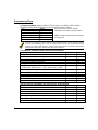
3URJUDPPLQJWKH6\VWHP
3URJUDPPLQJ2YHUYLHZ
The User Guide provides detailed information on the system’s options. See the next page for
entering program mode and programming steps. The following is a summary of the menu options.
Summary of Menu Options
No. Menu Option Used To…
Options available to all users
01 Hear Messages
listen to messages and memos
02 Record Memo
record memos for other users of the system
03 Caller ID log
view the log of callers
04 Privacy On/Off
turn privacy mode on or off
05 Record OGM
record greeting for each mailbox
06 System On/Off
turn answer mode on or off
07 System Time
set the system’s time
Options available to Master/Installer only
08 CID Display On/Off
turn the CID display on at keypads
ff.
09 Keypad CID On/Off
turn on CID announcement at keypads
10 Aux CID On/Off
turn on CID announcment at speakers
11 Aux Volume
set the auxiliary speaker volume
12 Toll Saver On/Off
turn the toll saver feature on or off
13 Message Beeps On/Off
turn on dial tone message beeps feature
14 HF Keypad On/Off
turn keypad call screening (hands-free) on/off
15 HF Aux On/Off
turn auxiliary speaker hands-free on/off
16 Handset On/Off
turn handset hands-free on/off
17 Ring Answer
set the ring answer count (2-8)
18 Access Key
assign the Quick Access key (1-4)
19 Caller ID Settings
program distinctive ring, mailbox, voice tag
20 Memory Dial Settings
program memory dial phone numbers
21 User Code Settings
program user codes, mailboxes, keypad message
22 Zone Voice Tags
record zone voice tags
23 PBAX Line
set system for use with PBAX network
(not available for downloading)

– 7 –
3URJUDPPLQJ6WHSV
To begin programming: installer (default = 4321) or master code (default = 2468) + [
∗
] key.
The keypad displays the Hear Messages prompt. Navigate the menus as follows:
To… Press… Refer to the User Guide for detailed
select displayed option [0] explanations on using the systems features.
display next option [
∗
]
display previous option [#] NOTE: Installer code has same access rights
GOTO a specific option [7] + option no. as master code.
exit the system [9]
To reset the system back to the original factory defaults settings, power down the system,
short the two defaulting pins on the PC board, then power up the system with the pins
shorted. The system will announce “system ready” after about 20 seconds, indicating the
defaults have taken effect. Remove the short across the pins.
To program the TeleSmart system, you need to do the following:
System Options: Default Menu
•
Set the system’s time 07
•
Set the ring answer count 4 17
•
Record zone voice tags for up to 22 zones --- 22
•
Store up to 15 memory dial numbers --- 20
User Options: Menu
•
Assign user codes and mailboxes 21
Default Codes: installer (user 7) = 4321; master (user 6) = 2468
•
Record outgoing messages 05
•
Turn telephone message beeps on/off per user’s preference 13
•
Assign a Quick Access Key 18
Caller ID Options: Menu
•
Set Caller ID displays and announcement on/off per user’s preferences 08-11
•
Program Caller ID settings for up to 25 phone numbers 19
After the system is programmed, show the user how to do the following:
Feature Menu
•
Turn System on and off 06
•
Record memos 02
•
Listen to messages 01
•
View the Caller ID Log 03
•
Turn the privacy feature on and off 04
•
Set call screening options (keypad, aux speaker, handset) 14-16
•
Set the toll saver on or off 12

– 8 –
'RZQORDGLQJ
Central Station Initiated Download
TeleSmart cannot be in program mode or playback mode when downloading.
1. Central Station dials the TeleSmart phone number
2. TeleSmart answers on the programmed ring count, or, if Answer mode is off,
answers on 10th ring. If modem carrier is detected, the downloading session begins.
If modem carrier is not detected, TeleSMART hangs up.
NOTE: PBAX Line option (option 23) is not available for downloading. This feature
must be set at a TeleSmart keypad.

– 9 –
5HJXODWRU\$JHQF\6WDWHPHQWV
RADIO FREQUENCY EMISSIONS
Federal Communications Commission (FCC) Part 15
This device complies with part 15 of the FCC rules. Operation is subject to the following two conditions:
(1) This device may not cause harmful interference, and (2) this device must accept any interference
received, including interference that may cause undesired operation.
Industry Canada
This Class B digital apparatus complies with Canadian ICES-003.
Cet Appareil numérique de la classe B est conforme à la norme NMB-003 du Canada.
TELEPHONE/MODEM INTERFACE
FCC Part 68
This equipment complies with Part 68 of the FCC rules. On the front cover of this equipment is a label
that contains the FCC registration number and Ringer Equivalence Number (REN). You must provide
this information to the telephone company when requested.
This equipment uses the following USOC jack: RJ31X
This equipment may not be used on telephone-company-provided coin service. Connection to party lines
is subject to state tariffs. This equipment is hearing-aid compatible.
Industry Canada
NOTICE:
The Industry Canada Label identifies certified equipment. This certification means that the
equipment meets telecommunications network protective, operational and safety requirements as
prescribed in the appropriate Terminal Equipment Technical Requirements document(s). The
Department does not guarantee the equipment will operate to the user’s satisfaction.
Before installing this equipment, users should ensure that it is permissible to be connected to the facilities
of the local telecommunications company. The equipment must also be installed using an acceptable
method of connection. The customer should be aware that compliance with the above conditions may not
prevent degradation of service in some situations.
Repairs to certified equipment should be coordinated by a representative designated by the supplier. Any
repairs or alterations made by the user to this equipment, or equipment malfunctions, may give the
telecommunications company to request the user to disconnect the equipment.
Users should ensure for their own protection that the electrical ground connections of the power utility,
telephone lines and internal metallic water pipe system, if present, are connected together, This
precaution may be particularly important in rural areas.
Caution:
Users should not attempt to make such connections themselves but should contact appropriate
electric inspection authority, or electrician, as appropriate.
Ringer Equivalence Number Notice:
The
Ringer Equivalence Number
(REN) assigned to each terminal device provides an indication of the
maximum number of terminals allowed to be connected to a telephone interface. The termination on an
interface may consist of any combination of devices subject only to the requirement that the sum of the
Ringer Equivalence Numbers of all the devices does not exceed 5.

– 10 –
5HJXODWRU\$JHQF\6WDWHPHQWV
Industrie Canada
AVIS:
l’étiquette d’Industrie Canada identifie le matériel homologué. Cette étiquette certifie que le
matériel est conforme aux normes de protection, d’exploitation et de sécurité des réseaux de
télécommunications, comme le prescrivent les documents concernant les exigences techniques relatives
au matériel terminal. Le Ministère n’assure toutefois pas que le matériel fonctionnera à la satisfaction de
l’utilisateur.
Avant d’installer ce matériel, l’utilisateur doit s’assurer qu’il est permis de le raccorder aux installations de
l’enterprise locale de télécommunication. Le matériel doit également être installé en suivant une méthode
acceptée da raccordement. L’abonné ne doit pas oublier qu’il est possible que la conformité aux
conditions énoncées ci-dessus n’empêche pas la dégradation du service dans certaines situations.
Les réparations de matériel nomologué doivent être coordonnées par un représentant désigné par le
fournisseur. L’entreprise de télécommunications peut demander à l’utilisateur da débrancher un appareil
à la suite de réparations ou de modifications effectuées par l’utilisateur ou à cause de mauvais
fonctionnement.
Pour sa propre protection, l’utilisateur doit s’assurer que tous les fils de mise à la terre de la source
d’energie électrique, de lignes téléphoniques et des canalisations d’eau métalliques, s’il y en a, sont
raccordés ensemble. Cette précaution est particulièrement importante dans les régions rurales.
Avertissement :
L’utilisateur ne doit pas tenter de faire ces raccordements lui-même; il doit avoir racours
à un service d’inspection des installations électriques, ou à un électricien, selon le cas.
AVIS : L’indice d’équivalence de la sonnerie
(IES) assigné à chaque dispositif terminal indique le
nombre maximal de terminaux qui peuvent être raccordés à une interface. La terminaison d’une interface
téléphonique peut consister en une combinaison de quelques dispositifs, à la seule condition que la
somme d’indices d’équivalence de la sonnerie de tous les dispositifs n’excède pas 5.

– 11 –
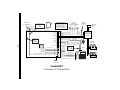
TeleSMART
Summary of Connections
CONTROL’S
AC TERMINALS
TYPICAL
CONTROL’S
PHONE TERMINALS
TIP
RING
TIP
RING
TIP
RING
REAL-TIME CLOCK (RTC)
EARTH
GROUND
GRN (DATA IN)
RED (+12VDC)
BLACK (–)
YEL (DATA OUT)
BLACK (–) GND
YEL (DATA OUT)
AUDIO
IN
SPEAKER
(8 ohm)
KEYPAD
LOCAL
INCOMING
USE OUTER
WIRES OF
AUDIO CABLE
DIRECT
CONNECT
CORD
RJ31X
TELEPHONE
JACK
INCOMING
PHONE
LINE
HOUSE
PHONES
SHORT PINS
TO RESTORE
DEFAULT
SETTINGS
1
2
3
4
5
6
7
8
9
10
11
12
13
14
15
16
17
18
FROM
CONTROL
HOUSE
PHONES
AUX
SPEAKER
KEYPADS
(CA38A in Canada)
CONTROL'S
KEYPAD
TERMINALS
KEYPAD
AUDIO
BUS
CONNECT EITHER
AC TERMINAL TO
RTC
TERMINAL
®
1
OFF
4
MAX
7
INSTANT
READY
2
AWAY
5
TEST
8
CODE
0
3
STAY
6
BYPASS
9
CHIME
#
ARMED
READY
MESSAGE
GREEN (DATA IN)
RED (+12VDC)
TROUBLESHOOTING NOTE:
If the system hangs up the
phone line when calling in from a
remote location, check the
phone connection terminals:
Term. 17/18 = from control
Term. 15/16 = to house phones

ADEMCO LIMITED WARRANTY
Alarm Device Manufacturing Company, a Division of Pittway Corporation, and its divisions, subsidiaries, and
affiliates ("Seller"), 165 Eileen Way, Syosset, New York 11791, warrants its products to be in conformance
with its own plans and specifications and to be free from defects in materials and workmanship under normal
use and service for 24 months from the date stamp control on the product or, for products not having an
ADEMCO date stamp, for 12 months from date of original purchase unless the installation instructions or
catalog sets forth a shorter period, in which case the shorter period shall apply. Seller's obligation shall be
limited to repairing or replacing, at its option, free of charge for materials or labor, any product which is
proved not in compliance with Seller's specifications or proves defective in materials or workmanship under
normal use and service. Seller shall have no obligation under this Limited Warranty or otherwise if the
product is altered or improperly repaired or serviced by anyone other than ADEMCO factory service. For
warranty service, return product, transportation prepaid, to your nearest ADEMCO distributor.
THERE ARE NO WARRANTIES, EXPRESS OR IMPLIED, OF MERCHANTABILITY, OR FITNESS FOR A
PARTICULAR PURPOSE OR OTHERWISE, WHICH EXTEND BEYOND THE DESCRIPTION ON THE
FACE HEREOF. IN NO CASE SHALL SELLER BE LIABLE TO ANYONE FOR ANY CONSEQUENTIAL OR
INCIDENTAL DAMAGES FOR BREACH OF THIS OR ANY OTHER WARRANTY, EXPRESS OR IMPLIED,
OR UPON ANY OTHER BASIS OF LIABILITY WHATSOEVER, EVEN IF THE LOSS OR DAMAGE IS
CAUSED BY THE SELLER'S OWN NEGLIGENCE OR FAULT.
Seller does not represent that the products it sells may not be compromised or circumvented; that the
products will prevent any personal injury or property loss by burglary, robbery, fire, or otherwise; or that the
products will in all cases provide adequate warning or protection. Customer understands that a properly
installed and maintained alarm may only reduce the risk of a burglary, robbery, fire, or other events
occurring without providing an alarm, but it is not insurance or a guarantee that such will not occur or that
there will be no personal injury or property loss as a result. CONSEQUENTLY, SELLER SHALL HAVE NO
LIABILITY FOR ANY PERSONAL INJURY, PROPERTY DAMAGE, OR OTHER LOSS BASED ON A
CLAIM THE PRODUCT FAILED TO GIVE WARNING. HOWEVER, IF SELLER IS HELD LIABLE,
WHETHER DIRECTLY OR INDIRECTLY, FOR ANY LOSS OR DAMAGE ARISING UNDER THIS LIMITED
WARRANTY OR OTHERWISE, REGARDLESS OF CAUSE OR ORIGIN, SELLER'S MAXIMUM LIABILITY
SHALL NOT IN ANY CASE EXCEED THE PURCHASE PRICE OF THE PRODUCT, WHICH SHALL BE
THE COMPLETE AND EXCLUSIVE REMEDY AGAINST SELLER. This warranty replaces any previous
warranties and is the only warranty made by Seller on this product. No increase or alteration, written or
verbal, of the obligations of this Limited Warranty is authorised.
®
ALARM DEVICE MANUFACTURING COMPANY
A DIVISION OF PITTWAY CORPORATION
165 Eileen Way, Syosset, NY 11791
Copyright © 2000 Pittway Corporation
¬.95l
K3950V2 3/01
-
 1
1
-
 2
2
-
 3
3
-
 4
4
-
 5
5
-
 6
6
-
 7
7
-
 8
8
-
 9
9
-
 10
10
-
 11
11
-
 12
12


ADEMCO TeleSmart Installation And Setup Manual
- Taper
- Installation And Setup Manual
dans d''autres langues
- English: ADEMCO TeleSmart
Documents connexes
Autres documents
-
Honeywell 408EU Manuel utilisateur
-
AT&T SynJ SB67138 Manuel utilisateur
-
Clarity CLS 45i Manuel utilisateur
-
Nuvo Concerto NV-I8DMS Manuel utilisateur
-
Serene HD-70 Mode d'emploi
-
Motorola B801 Manuel utilisateur
-
VTech CM18045 Manuel utilisateur
-
DSC WTK5504 Manuel utilisateur
-
Nuvo Essentia NV-E6D-UK Manuel utilisateur
-