Champion Power Equipment 46535 Manuel utilisateur
- Catégorie
- Groupes électrogènes
- Taper
- Manuel utilisateur

Congratulations on your purchase of a Champion Power Equipment generator. CPE designs and builds generators to
strict specifications and with proper use and maintenance this generator should bring you years of satisfying service.
Read, study, and follow all instructions before operating this device. Failure to heed these instructions may
result in personal injury and/or property damage.
WARNING
Your generator can develop tremendous power forces and if used unsafely or improperly could result in property damage, serious
injury, or death. Throughout this manual you will find the following symbols for caution, warning, and danger. Pay particular attention to
the notes preceded by these symbols as they are written for your safety. Ultimately, safe operation of this device rests with you, the
operator.
Indicates a hazard which, if not avoided, will result in death or serious injury.
Indicates a potentially hazardous situation which, if not avoided could result in death or serious injury.
Indicates a potentially hazardous situation which, if not avoided, may result in minor or moderate injury or
equipment damage. This notation is also used to alert against unsafe practices.
CAUTION
SAFETY PRECAUTIONS
SAFETY AND OPERATION INSTRUCTIONS
Failure to follow these instructions and warnings may result in death, personal injury, or property damage.
WARNING
DANGER
Gasoline engines produce toxic carbon monoxide exhaust fumes. Breathing exhaust fumes will cause serious injury
or death.
WARNING
No modifications, alterations, or deviation to the generator are authorized by the manufacturer and should not be made.
Read, study, and understand the operator's manual prior to operation of this product. Read, study and understand the
engine manual prior to operation. Follow all warnings and instructions.
Know your equipment. Check the applications, limitations, and potential hazards with this unit and its placement or
location.
The engine exhaust from this product contains chemicals known to the State of California to cause cancer, birth defects or
other reproductive harm.
Gasoline is flammable. Check for spilled fuel or fuel leaks. Stop engine and allow to cool at least 2 minutes before
refueling.
Equipment must be used on a hard, level surface, free from grease, fuel and other combustible materials.
Engine must not be run at excessive speeds. Operating an engine at excessive speeds increases the hazard of personal
injury. Do not tamper with the parts which may increase or decrease the speed of the engine.
Do not operate this generator in the rain or unusually wet conditions.
This generator is designed for outdoor use only; do not use this generator inside any building or enclosure including the
generator compartment of a recreational vehicle (RV), garages, basements, crawl spaces, and other locations where CO
gas can collect and cause death or injury..Fire or an explosion may result.
No user-performed modifications, including venting of exhaust and/or cooling ventilation are authorized by the
manufacturer, Also, allow at least two feet of clearance on all sides of the generator even while operating the unit
outdoors.
If this unit is used for backup power in the event of a utility power failure, the following step must be taken: Before
connecting the generator to an electrical system, open the main circuit breaker or main switch serving the system, to
isolate the generator system from the electric utility. Failure to isolate the generator and utility systems may result in
damage to the generator and may also result in injury or death to electric utility workers, due to a back feed of electrical
energy.
This product is equipped with a spark-arresting muffler. If the product will be used around flammable materials, or on land
covered with materials such as agricultural crops, forest, brush, grass, or other similar items, then the approved spark
arrester must be installed. SPARK-ARRESTERS ARE REQUIRED IN THE STATE OF CALIFORNIA. Spark arresters are
also required on some U.S. Forest Service land and may also be legally required under other statutes and ordinances.
Never step over a generator.
Failure to heed these warnings may result in personal injury and/or property damage. No modifications, alterations, or
deviations to the generator are authorized by the manufacturer and should not be made.
Engine speed has been factory set to provide safe operation. Tampering with the engine speed adjustment could result in
overheating of attachments and could cause a fire. Never attempt to “speed up” the engine to obtain more performance.
Both the output voltage and frequency will be thrown out of standard by this practice, endangering attachments and the
user.
WARNING
WARNING
WARNING
WARNING
WARNING
WARNING
WARNING
WARNING
WARNING
WARNING
WARNING
WARNING
WARNING
WARNING
DANGER
WARNING
1

2
CAUTION
This generator has been shipped from the factory without oil in the crankcase. Operating the unit without oil can ruin the
engine.
You MUST unplug any load from the generator before starting. This will help to prevent permanent damage to any
appliances.
Do not exceed rated capacity of current draw. Current load must be kept within rating on the generator label. Overloading
will damage the unit and/or shorten its life.
For starting, grasp the starter grip and pull slowly until you feel resistance. Then pull firmly. Repeat if necessary with
choke opened slightly. When engine starts, open the choke gradually until the engine is warm.
CAUTION
CAUTION
CAUTION
INCLUDED WITH YOUR GENERATOR
1. Generator
2. Battery Cable
3. Wheel Kit (1 axle, 2 wheels, 2 vibration
mounts, 1 handle assembly, 1 support leg)
4. Bolt Kit (2 wheel retaining pins, 2 flat
washers, 10 cap screws and nuts
5. Spark Arrestor, Cover and 2 Screws w/ Lock Washers
1 set
1 set
1 set
1 set
1 set
Never refuel a generator while it is in operation. Make sure the generator is not running. (This is a severe risk of fire.)
WARNING
(2) (3) (4) (5)
NOT INCLUDED WITH YOUR GENERATOR
(1) (2)
1. NEMA L14-20P
2. Standard 120V 3-Prong Plug
Note: These are not included with your generator.


4
RUNNING WATTAGE GUIDE
Starting loads may need as much as 3 times the Running Wattage for Electrical Motors. Check your appliance rating before using generator.
0 4000500 1000 1500 2000 2500 3000 3500
Air Conditioner (12,000 BTU)
Air Conditioner (20,000 BTU)
Battery Charger 20 AMP
Battery Charger 12V DC
Belt Sander 3”
Bench Grinder 6”
Chain Saw
Circular Saw (6-12”)
Clothes Washer
Coffee Maker
Compressor (1HP)
Compressor (½ HP)
Compressor (3/4 HP)
Curling Iron
Demolition Hammer
Disc Sander (9”)
Edge Trimmer
Electric Blanket
Electrical Nail Gun
Electric Range - One Element
Electric Skillet
Freezer
Furnace Fan (1/3 HP)
Hair Dryer
Hand Drill (1”)
Hand Drill (½”)
Hand Drill (1/4”)
Hand Drill (3/8”)
Hedge Trimmer
Home Security
Impact Wrench
Jet Pump
Jigsaw
Lawn Mower
Light Bulb
Microwave
Milk Cooler
Oil Burner on Furnace
Oil Fired Space Heater (140,000 BTU)
Oil Fired Space Heater (30,000 BTU)
Oil Fired Space Heater (85,000 BTU)
Paint Sprayer, Airless (1/3 HP)
Paint Sprayer, Airless (handheld)
Portable Heater (5,000 BTU)
Radio
Refrigerator
Refrigerator/Freezer
Slow Cooker
Small Refrigerator
Submersible Pump (1 HP)
Submersible Pump (½ HP)
Submersible Pump (1-1/2 HP)
Sump Pump
Table Saw
Television
Toaster Oven
Water Heater
Weed Trimmer
1700
3300
500
110
1000
700
1200
800
1200
1000
2000
1400
1800
700
1300
1200
500
230
1200
1500
1250
500
1200
1200
1100
750
250
500
450
100
500
800
550
1200
100
700
1100
300
400
150
225
600
150
1550
50
600
1200
200
500
2000
1500
2800
600
1750
400
1500
4000
500

GENERATOR ASSEMBLY AND MOUNTING
1. If your generator was delivered with two L-shaped metal shipping brackets mounted underneath the engine, these brackets must
be removed. These brackets were installed temporarily on some generators for shipping only and prevent the rubber isolation
mounts beneath the engine and generator from functioning properly.
2. Your Champion Generator is supplied with a wheel kit. If you want to install the wheel kit on your unit, please follow the following
instructions.
a. Place the bottom of the generator cradle on a flat, even surface. Temporarily place unit on blocks to ease assembly.
b. Attach the axle assembly to the cradle frame using four cap screws (M8 x 20) and nuts as shown (Fig 1).
c. Slide a wheel and a flat washer over the axle (Fig 2), and then secure the wheel with a retaining pin.
d. Install the other wheel in the same manner.
3. Secure each vibration mount to the support leg with a cap screw (M8 x 30) and nut (Fig 3).
4. Secure the support leg to the cradle with cap screws (M8 x 20) and nuts (Fig 4).
5. Position the handle on the cradle and attach with cap screws (M8 x 45) and nuts (Fig 5).
6. Check that all fasteners are tight.
7. If the included spark arrester insert is to be used, installation should be performed as follows. Insert the spark arrester screen into
the muffler outlet. Secure the spark arrester by placing the cover plate over the end of the screen, with lettering facing outward.
Secure the cover plate with the two screws and lock washers provided with the spark arrester kit.
FIG. 3
FIG. 4 FIG. 5
BEFORE OPERATION
Grounding the generator provides extra safety.
The National Electric Code requires that this product be properly connected to an appropriate ground to help prevent electric shock.
WARNING
Failure to properly ground the generator can result in electric shock.
A ground terminal connected to the frame of the generator has been provided on the front panel for this purpose. For
remote grounding, connect a length of heavy gauge (12 AWG min.) copper wire between the generator Ground Terminal
and a copper rod driven into the ground. This should provide a suitable ground connection. CPE recommends that you
consult with a local electrician to insure that local codes are being adhered to.
5
FIG. 2FIG. 1

¼

7
TROUBLE SHOOTING GUIDE
PROBLEM CAUSE CORRECTION
Engine will not start Low on fuel or oil
Ignition switches in off position
Faulty spark plug
Choke in wrong position
Fuel shut-off valve in closed position
Unit loaded during start-up
Spark plug wire loose
Add fuel or oil
Turn to “ON” position
Replace spark plug
Adjust choke accordingly
Open fuel shut-off valve
Remove load from unit
Attach wire to spark plug
No electrical output Faulty receptacle
Circuit breaker kicked out
Defective capacitor
Faulty brush assembly
Faulty power cord
Faulty AVR
Loose wiring
Have Service Center replace
Depress and reset
Have Service Center replace capacitor
Replace brush assembly
Replace cord
Have Service Center replace AVR
Inspect and tighten wiring connections
Repeated circuit
breaker tripping
Overload
Faulty cords or equipment
Reduce load. Depress and reset
Check for damage, bare, or frayed wires. Replace
Generator overheating Generator overloaded
Insufficient ventilation
Reduce load
Move to adequate supply of fresh air, check for
air restriction


SERVICE INFORMATION
A = Intermittent use (less than 1 hour) or colder temperatures, below 60°F
B = Medium use (less than 3 hours) or seasonal temperatures 50°F 80°F
C = Extreme use (continuous use) or hot climates 80°F-100°F
Spark Plug, NGK or equivalent
Spark Plug Gap
Valve Clearance, Cold
A BP6ES B BP7ES C BP8ES
0.70 / 0.80mm (.028 / .031 in.)
Intake 0.13 / 0.17mm (.005 / .007 in.)
Exhaust 0.18 / 0.22mm (.007 / .009 in.)
ADDING / CHECKING OIL LEVEL
1) Remove oil fill cap / dipstick to add oil
2) Add 0.6 L (0.63 qt.) oil and replace cap / dipstick
3) To check oil level - remove cap/dipstick and wipe it clean. Insert
cap/dipstick into the filler, but do NOT screw it in. Oil should
appear on dipstick.
4) If more oil is required add slowly
5) Oil should be filled at least to the bottom of the threads but not above the
top of the threads when on a level surface.
MAXIMUM FILL
MINIMUM FILL
DRAIN PLUG
DIP STICK
9
CAUTION
This engine is equipped with a “low oil shut-off” and the engine will stop when engine oil falls below the minimum safe
level. Add oil immediately then restart engine.
CHECK ENGINE OIL LEVEL DAILY AND ADD AS NEEDED!
REGULAR SERVICE PERIOD : Perform at every indicated month or operating hour interval, whichever comes first.
EACH USE
FIRST
MONTH OR
5 HOURS
FIRST 10
HOURS
EVERY
3 MONTHS
OR 50 HOURS
EVERY
6 MONTHS
OR 100 HRS
ITEM
Check level
Change
Check
Clean
Clean
Clean-Readjust
Check-Readjust
Clean
Clean
Replace if necessary
Engine Oil
Air Cleaner
Sediment cup
Spark plug
Valve clearence*
Spark Arrester
Fuel tank and filter*
Fuel Line
Every 3 years
°F-20 0 20 40 60 80 100 120
10W-30
5W-30
30
MAINTENANCE SCHEDULE:
* Recommended for experienced owner or service center.
• Tampering with the factory set governor could void your warranty.
• Improper maintenance will void your warranty.

10
TO OBTAIN WARRANTY SERVICE:
You must take your CPE engine or the product on which it is installed, along with your warranty registration card or other proof of original
purchase date, at your expense, to any Champion Power Equipment dealer who is authorized by Champion Power Equipment, Inc. to sell and
service that CPE product during his normal business hours. Claims for repair or adjustment found to be caused solely by defects in material or
workmanship will not be denied because the engine was not properly maintained and used.
If you have any questions regarding your warranty rights and responsibilities, or to obtain warranty service, please write or call the Customer
service of Champion Power Equipment, Inc.
Champion Power Equipment, Inc.
Customer Service
10006 Santa Fe Springs Rd.
Santa Fe Springs, CA 90670
Customer Service: Mon Fri 8:30 AM - 5:00 PM (PST/PDT)
Toll Free: 1-877-338-0999
Fax no.: 1-562-236-9429
Technical Service: Mon Fri 8:30 AM - 5:00 PM (PST/PDT)
Toll Free: 1-877-338-0999
Email: [email protected]
CHAMPION POWER EQUIPMENT
1 YEAR LIMITED WARRANTY
Warranty Qualifications
Champion Power Equipment (CPE) will register this warranty upon receipt of your Warranty Registration Card and a copy of your sales receipt
from one of CPE's retail locations as proof of purchase.
Please submit your warranty registration and your receipt within ten (10) days of the date of purchase.
Champion Power Equipment Repair/Replacement Warranty
CPE warrants to the original purchaser that the mechanical and electrical components will be free of defects in material and workmanship for a
period of one (1) year from the original date of purchase (90 days for commercial & industrial use). This warranty only applies to the original
purchaser and is not transferable.
Do not return the unit to the place of purchase
Contact CPE's Technical Service and CPE will troubleshoot any issue via phone or e-mail. If the problem is not corrected by this method, CPE
will, at its option, authorize evaluation, repair or replacement of the defective part or component at a CPE Service Center. CPE will provide you
with a case number for warranty service. Please keep it for future reference. Repairs or replacements without prior authorization, or at an
unauthorized repair facility, will not be covered by this warranty.
Warranty Exclusions
This warranty will not apply to parts and/or labor if this generator is deemed to have been misused, neglected, involved in an accident, abused,
loaded beyond the generator's limits, modified, installed improperly or connected incorrectly to any electrical component. Cosmetic defects
such as paint, decals, etc., are excluded from this warranty. *Warranty is Limited to 90-days from purchase for Commercial use, including
Rentals.
Limits of Implied Warranty and Consequential Damage
Champion Power Equipment disclaims any obligation to cover any loss of time, use of this product, freight, or any incidental or consequential
claim by anyone from using this generator. THIS WARRANTY IS IN LIEU OF ALL OTHER WARRANTIES, EXPRESS OR IMPLIED,
INCLUDING WARRANTIES OF MERCHANTABILITY OR FITNESS FOR A PARTICULAR PURPOSE
A unit provided as an exchange will be subject to the warranty of the original unit. The length of the warranty governing the exchanged unit will
remain calculated by reference to the purchase date of the original unit.
This warranty gives you certain legal rights which may change from state to state. Your state may also have other rights you may be entitled to
that are not listed within this warranty.
Champion Power Equipment, Inc.
Customer Service
10006 Santa Fe Springs Rd.
Santa Fe Springs, CA 90670
Customer Service: Mon Fri 8:30 AM - 5:00 PM (PST/PDT)
Toll Free: 1-877-338-0999
Fax no.: 1-562-236-9429
Technical Service: Mon Fri 8:30 AM - 5:00 PM (PST/PDT)
Toll Free: 1-877-338-0999
Email: [email protected]


Item
1
2
3
4
5
6
7
8
9
10
11
12
13
14
15
16
17
18
19
20
21
22
23
24
25
26
27
28
29
30
31
32
33
34
35
36
37
38
39
40
41
42
43
44
45
46
47
48
49
50
51
52
53
54
55
56
57
58
59
60
61
62
63
64
65
66
67
68
69
70
71
72
73
74
75
76
Part Number
ST168FD-1160100
GB819-85
ST168FD-1160200
ST168FD-1160200
ST168F-1160500
ST168FD-1160001A
GB5789-86
ST168FD-1163000
ST168FD-1160400
ST168FD-1160002A
ST168FD-1100200-1
GB6177-86
GB5789-86
ST168FD-1100002B
ST02FD-1152035-CSA
ST02FD-1152002-2
GB5789-86
GB5781-87
ST168FD-1150230-CSA
GB5781-86
ST168FD-1152031-CSA
ST168FD-1152004
ST02FD-1152032
GB5789-86
ST02FD-1152001
ST02FD-1152020-CSA
GB5780-86
GB90-85
GB279-88 6202
ST02FD-1152010-CSA
ST02FD-1152009
ST168FD-1030007
GB5789-86
ST188FD-1743002-C
GB6170-86
ST168FD-1150401
GB5789-86
GB5789-86
ST168FD-1710004
ST02FD-1151200C-CSA
ST02FD-1151206M
ST02FD-1151200B-CSA
ST02FD-1151204A-CSA
ST168FD-1716000-CSA-2
ST02FD-1151205A
ST02FD-1151211-CSA
GB/T91-2000
GB97.1-85
ST177FD-1152300
ST168FD-1150301-M
ST02FD-1151300-1
ST02FD-1151400
GB5789-86
ST02FD-1151002
GB5789-86
ST168FD-1151300D-CSA
ST168F-II-1000000
ST168FD-1130003-CPE
ST168FD-1130005
ST02FD-1151201A
ST168FD-1111100
ST168FD-1090100
ST168FD-1090002
ST168FD-1090003
ST168FD-1090004
ST168FD-1090200
GB5789-86
GB93-1987
ST188FD-1100010-88
ST188FD-1180121
GB5789-86
ST02FD-1151300-CSA
ST02FD-1151202A-CSA
ST02FD-1151207-M
ST02FD-1151208-M
ST02FD-1151036
Description
Fuel Meter Assy
Screw M5×6
Fuel Tank Cap
Fuel Tank Cap Seal
Fuel Filler
Fuel Tank
Bolt M6×16
Tank Rubber
Fuel Cock
Fuel Tank
Muffler
Nut M6
Bolt M6×20
Muffler Stay
Brush Assy
Generator End Cover
Bolt M5×10
Bolt M5×16
Terminal
Bolt M5×15
AVR
Diode Assy
End Cover
Flange Bolt M6×130
Stator Cover
Stator Assy
Flange Bolt M8×210
Washer 6
Bearing 6202
Rotor Comp
Cooling Fan
Crankcase Cover
Flange Bolt M8×32
Vibration Mount
Nut M8
Support Leg
Flange Bolt M8×16
Bolt M5×12
Red Positive Terminal
Black Negative Terminal
Receptacle
Electrical Wire Safeguard
Receptacle
Volt Meter
AC250V.20A DOUBLE POLES
Switch
Control Panel
Cotter Pin M3.2×40
Flat Washer 17
8in Wheel (Solid)
Axle (23.5in)
Bottom Rubber
Handle
Flange Bolt M8×40
Muffler Cover
Flange Bolt M6×12
Frame
Engine
Carburetor
Packing
Choke Lever Comp
Control Assy
Air Cleaner Case Comp
Air Cleaner Seal
Separator
Element
Air Cleaner Cover Comp
Bolt M5×10
Spring Washer 5
Spark Arrester Cover
Spark Arrester Assy
Flange Bolt M6×35
Control Box
DC.Fuse 10A
Earth Line
Earth Bolt
Brush Assy Cover Board
Qty.
1
2
1
1
1
1
4
4
1
1
1
1
1
1
1
1
2
2
1
2
1
1
1
4
1
1
1
1
1
1
1
1
2
2
16
1
6
4
1
1
2
1
1
1
2
1
1
2
2
2
1
4
1
2
1
4
1
1
1
1
1
1
1
1
1
1
1
2
2
1
1
3
1
1
1
1
1

Nous vous félicitons de votre acquisition d'un générateur Champion Power Equipment. CPE conçoit et construit des
générateurs avec des spécifications rigoureuses et capables de fonctionner de manière satisfaisante pendant des années
dans des conditions d'utilisation et de maintenance adéquates.
Lire attentivement et respecter toutes les instructions avant la mise en service de cet appareil. Le
non respect de ces instructions peut entraîner des blessures corporelles et/ou dommages
AVERTISSEMENT
Ce générateur est doté de puissantes capacités électriques, et toute utilisation dangereuse ou impropre peut occasionner des
dommages matériels ainsi que des blessures corporelles graves, voire mortelles. Tout au long de ce manuel, vous découvrirez les
symboles « attention », « mise en garde » et « danger » suivants. Veuillez faire particulièrement attention aux remarques précédées de
ces symboles car elles sont destinées à votre sécurité. Ultimement, la sûreté d'exploitation de cet appareil incombe à l'opérateur, c'est-
à-dire vous-même.
Indique une situation de danger éventuel qui, si elle n'est pas évitée, peut occasionner des blessures légères
ou modérées, ou endommager le matériel. Cette notation a pour but également d'attirer l'attention sur les
pratiques dangereuses.
Indique une situation éventuellement dangereuse qui, si elle n'est pas évitée, peut entraîner des
blessures graves, voire mortelles.
Indique un risque qui, s'il n'est pas évité, entraînera des blessures graves, voire mortelles.
MESURES DE SÉCURITÉ
CONSIGNES DE SÉCURITÉ ET D'EXPLOITATION
Le non respect de ces consignes et mises en garde peut entraîner le décès, des blessures corporelles ou des
DANGER
Les moteurs à essence libèrent des émanations de monoxyde de carbone toxiques. Respirer ces émanations
occasionne des blessures graves ou mortelles.
Aucune modification, altération ou déviation du générateur n'est autorisée par le fabricant et ne doit être
effectuée.
Lire et étudier attentivement le manuel de l'opérateur avant de faire fonctionner ce produit. Lire et étudier
attentivement le manuel du moteur avant de le faire fonctionner. Respecter toutes les mises en garde et
instructions.
Connaissance du matériel. Vérifier les applications, limites et dangers éventuels accompagnant cet appareil et
son emplacement ou positionnement.
Les émanations du moteur de cet article contiennent des produits chimiques qui, dans l'état de Californie, sont
connus pour provoquer cancers, malformations congénitales ou autres problèmes de reproduction.
L'essence est inflammable. Vérifier l'absence de déversements ou de fuites de carburant. Éteindre le moteur et
le laisser refroidir pendant au moins 2 minutes avant de remettre de l'essence.
Le matériel doit être utilisé sur une surface dure et à niveau, sans graisses, carburants et autres substances
combustibles.
Le moteur ne doit pas tourner à des vitesses excessives. Le fonctionnement d'un moteur à une vitesse
excessive augmente les risques de blessures corporelles. Ne pas toucher aux pièces pouvant augmenter ou
diminuer la vitesse du moteur.
Ne pas faire fonctionner ce générateur sous la pluie ou dans des conditions inhabituellement humides.
Ce générateur est conçu pour une utilisation extérieure uniquement; ne pas utiliser ce générateur à l'intérieur
de locaux ou d'espaces clos, y compris dans le compartiment à générateur d'un véhicule récréatif (VR), les
garages, sous-sols, galeries ou autres lieux où le CO2 peut s'accumuler et provoquer des blessures graves ou
mortelles. Un incendie ou une explosion pourrait survenir.
Aucune modification effectuée par l'utilisateur, y compris la ventilation des émanations et/ou une ventilation
refroidissante, n'est autorisée par le fabricant. De plus, laisser au moins 60 cm de dégagement de part et
d'autre du générateur lorsque l'appareil fonctionne dehors.
Si cet appareil est utilisé comme alimentation de secours dans l'éventualité d'une panne de courant électrique,
procéder comme suit: avant de relier le générateur à un système électrique, ouvrir le disjoncteur du circuit
principal ou le commutateur principal alimentant le système pour isoler le générateur du service d'électricité.
Si le générateur n'est pas isolé des systèmes de service public, il peut être endommagé et également blesser
ou tuer des électriciens du service public en raison du retour de tension de l'énergie électrique.
Ce produit est équipé d'un atténuateur pare-étincelles. Si le produit doit être utilisé en présence de substances
inflammables, ou sur un terrain couvert de cultures agricoles, forêts, buissons, herbes ou autres matières
similaires, il faut alors installer un pare-étincelles homologué. LES PARE-ÉTINCELLES SONT EXIGÉS DANS
L'ÉTAT DE CALIFORNIE. Les pare-étincelles sont également exigés sur certains terrains du Service des
forêts américain et peuvent aussi être légalement exigés dans le cadre de certains règlements et décrets.
DANGER
13
AVERTISSEMENT
ATTENTION
AVERTISSEMENT
AVERTISSEMENT
AVERTISSEMENT
AVERTISSEMENT
AVERTISSEMENT
AVERTISSEMENT
AVERTISSEMENT
AVERTISSEMENT
AVERTISSEMENT
AVERTISSEMENT
AVERTISSEMENT
AVERTISSEMENT
AVERTISSEMENT

Ne jamais marcher sur un générateur.
Le non respect de ces mises en garde peut occasionner des blessures corporelles et/ou des dommages
matériels. Aucune modification, altération ou déviation du générateur n'est autorisée par le fabricant et ne doit
être effectuée.
La vitesse du moteur a été réglée en usine pour en assurer la sûreté d'exploitation. L'altération du réglage de
la vitesse du moteur peut entraîner une surchauffe des pièces et provoquer un incendie. Ne jamais tenter «
d'accélérer » le moteur pour augmenter sa performance. Cette manœuvre a pour effet de dérégler la tension
de sortie et la fréquence, en mettant ainsi l'utilisateur en danger et en endommageant les accessoires.
AVERTISSEMENT
AVERTISSEMENT
AVERTISSEMENT
14
Ce générateur a été expédié de l'usine sans huile dans le carter. La mise en marche de l'appareil sans huile peut
détériorer le moteur.
Il FAUT débrancher toutes les charges du générateur avant sa mise en marche. Cette précaution permet d'éviter des
dommages permanents sur tout appareil électrique.
Ne pas excéder la puissance nominale du courant utilisé. La charge en courant doit rester dans les limites indiquées sur
l'étiquette du générateur. Toute surcharge endommagera l'appareil et/ou raccourcira sa longévité.
Pour démarrer, saisir la poignée du démarreur et la tirer lentement jusqu'à sentir une résistance. Ensuite, tirer
fermement. Recommencer si nécessaire en ouvrant légèrement l'échappement. Lorsque le moteur démarre, ouvrir
graduellement l'échappement jusqu'à ce que le moteur soit chaud.
Ne jamais remettre de carburant dans un générateur en fonctionnement. S'assurer que le générateur est à l'arrêt.
(Il existe un sérieux risque d'incendie).
AVERTISSEMENT
ATTENTION
ATTENTION
ATTENTION
ATTENTION
INCLUS AVEC VOTRE GÉNÉRATEUR
1. Générateur
2. Câble pour batterie
3. Jeu de roues (1 essieu, 2 roues, 2 silentblocs, 1 poignée, 1 support de soutien)
4. Visserie (2 tiges de retenue pour roue, 2 rondelles plates, 10 vis et écrous à chapeau
5. Pare-étincelles, couvercle et 2 vis avec rondelles de blocage
1 jeu
1 jeu
1 jeu
1 jeu
1 jeu
(2) (3) (4) (5)
NON INCLUS AVEC VOTRE GÉNÉRATEUR
(1) (2)
1. L14-20P NEMA
2. Prise triphasée standard 120 V
Remarque: Ces articles ne sont pas inclus avec votre générateur.


16
GUIDE DE PUISSANCE D'EXPLOITATION
Les charges de démarrage peuvent nécessiter jusqu'à trois fois la puissance de fonctionnement pour les moteurs électriques. Vérifier la
puissance nominale de l'appareil électrique avant d'utiliser le générateur.
0 4000500 1000 1500 2000 2500 3000 3500
Climatisation (12 000 BTU)
Climatisation (20 000 BTU)
Chargeur de batteries 20 A
Chargeur de batterie 12 V c.c.
Ponceuse à courroie 7,5 cm
Meuleuse d'établi 15 cm
Tronçonneuse
Scie circulaire (7,5-15 cm)
Machines à laver
Machine à café
Compresseur (1HP)
Compressor (½ HP)
Compressor (3/4 HP)
Fer à friser
Marteau piqueur
Ponçeuse à disques (23 cm)
Taille-bordure
Couverture chauffante
Pistolet goujonneur électrique
Cuisinière électrique Un élément
Poêle électrique
Congélateur
Ventilateur d'appareil de chauffage (1/3 HP)
Sèche-cheveux
Perceuse à main (1 po)
Perceuse à main (1/2 po)
Perceuse à main (1/4 po)
Perceuse à main (3/8 po)
Taille-haie
Sécurité à domicile
Clé à chocs
Pompe à jet
Scie sauteuse
Tondeur de pelouses
Ampoule électrique
Micro-ondes
Réfrigérant à lait
Brûleur à mazout sur appareil de chauffage
Radiateur portatif au mazout (140 000 BTU)
Radiateur portatif au mazout (30 000 BTU)
Radiateur portatif au mazout (85 000 BTU)
Pistolet sans air comprimé (1/3 HP)
Pistolet sans air comprimé (portatif)
Radiateur portatif (5 000 BTU)
Radio
Réfrigérateur
Réfrigérateur/congélateur
Mijoteuse
Petit réfrigérateur
Pompe submersible (1 HP)
Pompe submersible (1/2 HP)
Pompe submersible (1-1/2 HP)
Pompe de puisard
Table de sciage
Télévision
Grille-pain four
Chauffe-eau
Coupe-herbe
1700
3300
500
110
1000
700
1200
800
1200
1000
2000
1400
1800
700
1300
1200
500
230
1200
1500
1250
500
1200
1200
1100
750
250
500
450
100
500
800
550
1200
100
700
1100
300
400
150
225
600
150
1550
50
600
1200
200
500
2000
1500
2800
600
1750
400
1500
4000
500

ASSEMBLAGE ET MONTAGE DU GÉNÉRATEUR
1. Si le générateur a été livré avec deux supports d'expédition métalliques en forme de L montés sous le moteur, ces supports doivent être
retirés. Ces supports ont été installés temporairement sur certains générateurs uniquement pour éviter que les silentblocs situés sous le moteur
et le générateur aient un problème de fonctionnement.
2. Votre générateur Champion est livré avec un jeu de roues. Si l'on désire installer ce jeu de roues sur l'appareil, procéder comme suit :
a. Placer le dessous du berceau du générateur sur une surface plane et régulière. Placer temporairement l'appareil sur des blocs
pour faciliter l'assemblage.
b. Fixer la partie essieu au châssis du berceau à l'aide des quatre vis (M8 x 20) et écrous à chapeau comme indiqué (figure 1).
c. Faire glisser une roue et une rondelle plate sur l'essieu (figure 2), puis fixer la roue avec une clavette de retenue.
d. Installer l'autre roue de la même façon.
3. Fixer chaque silentbloc sur le support de soutien à l'aide d'une vis (M8 x 30) et d'un écrou à chapeau (figure 3).
4. Fixer le support de soutien au berceau avec les vis (M8 x 20) et les écrous à chapeau (figure 4).
5. Positionner la poignée sur le berceau et la fixer avec les vis (M8 x 45) et les écrous à chapeau (figure 5)
6. Vérifier que toutes les fixations sont bien serrées.
7. S'il est prévu d'utiliser le pare-étincelles inclus, procéder à son installation comme suit:
Insérer la grille du pare-étincelles dans la sortie de l'atténuateur. Fixer le pare-étincelles en plaçant la plaque de finition sur l'extrémité de la
grille, avec le lettrage dirigé sur l'extérieur. Fixer la plaque de finition avec deux vis et rondelles de blocage fournies avec le jeu du pare-
étincelles.
FIG. 1 FIG. 3
FIG. 4 FIG. 5
AVANT LA MISE EN MARCHE
La mise à la terre du générateur offre une sécurité supplémentaire.
Le NEC (National Electric Code) exige que ce produit soit mis à la terre de manière adéquate pour éviter les risques d'électrocution.
L'absence de la mise à la terre du générateur peut produire des chocs électriques.
Une borne de terre reliée au châssis du générateur est prévue à cet effet sur le panneau avant. Pour une mise
à la terre éloignée, brancher une longueur de fil de cuivre de gros calibre (12 AWG min.) entre la borne de
terre du générateur et un piquet en cuivre enfoncé dans le sol. Cette procédure devrait assurer une connexion
à la terre adéquate. CPE recommande de consulter votre électricien pour s'assurer que les réglementations
régionales sont respectées.
17
AVERTISSEMENT
FIG. 2

0,65

TROUBLE SHOOTING GUIDE
PROBLÈME CAUSE CORRECTION
Le moteur ne
démarre pas
Niveau de carburant ou d'huile trop bas
Interrupteur d'allumage sur « off » (arrêt)
Bougie d'allumage défectueuse
Échappement sur la mauvaise position
Vanne d'arrêt de carburant en position fermée
Unité chargée pendant le démarrage
Fil de la bougie non raccordé
Ajouter du carburant ou de l'huile
Mettre sur « ON » (marche)
Changer la bougie
Ajuster l'échappement en fonction
Ouvrir la vanne d'arrêt de carburant
Retirer la charge de l'appareil
Fixer le fil à la bougie
Pas de sortie
électrique
Prise défectueuse
Disjoncteur disjoncté
Condensateur défectueux
Balai défectueux
Cordon d'alimentation défectueux
AVR (régulateur de tension) défectueux
Câblage lâche
Faire effectuer le remplacement par le centre
de services
Appuyer et réinitialiser
Faire effectuer le remplacement du condensateur
par centre de services
Remplacer le balai
Remplacer le cordon
Faire effectuer le remplacement du AVR par le
centre de services
Inspecter et serrer les montages électriques
Déclenchement
répété du
disjoncteur
Surcharge
Cordons ou matériel défectueux
Réduire la charge. Appuyer et réinitialiser
Vérifier si les fils sont endommagés, dénudés ou
effilochés. Remplacer
Surchauffe du
générateur
Générateur surchargé
Aération insuffisante
Réduire la charge.
Déplacer de manière à obtenir un refroidissement
adéquat avec de l'air frais et vérifier le débit d'air.
19

La page est en cours de chargement...
La page est en cours de chargement...
La page est en cours de chargement...
La page est en cours de chargement...
-
 1
1
-
 2
2
-
 3
3
-
 4
4
-
 5
5
-
 6
6
-
 7
7
-
 8
8
-
 9
9
-
 10
10
-
 11
11
-
 12
12
-
 13
13
-
 14
14
-
 15
15
-
 16
16
-
 17
17
-
 18
18
-
 19
19
-
 20
20
-
 21
21
-
 22
22
-
 23
23
-
 24
24
Champion Power Equipment 46535 Manuel utilisateur
- Catégorie
- Groupes électrogènes
- Taper
- Manuel utilisateur
dans d''autres langues
Documents connexes
-
 Champion Power Equipment 44025 Manuel de l’opérateur
-
 Champion Power Equipment 40037 Manuel de l’opérateur
-
 Champion Power Equipment 46504 Manuel utilisateur
-
 Champion Power Equipment 40032 Manuel de l’opérateur
-
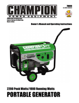 Champion Power Equipment 70009 Manuel utilisateur
-
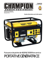 Champion Power Equipment 40020 Manuel de l’opérateur
-
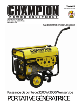 Champion Power Equipment 40025 Manuel de l’opérateur
-
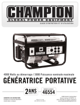 Champion Power Equipment 46554 Manuel utilisateur
-
 Champion Power Equipment 46558 Manuel utilisateur
-
 Champion Power Equipment 76554 Manuel utilisateur


