Whirlpool LDR3822PQ Manuel utilisateur
- Catégorie
- Sèche-linge
- Taper
- Manuel utilisateur

120 V Electric
Compact Dryer
Use and Care Guide
Table of Contents
W11263363A
W11265699A - SP
SÉCURITÉ DE LA SÉCHEUSE ....................................................16
SPÉCIFICATIONS .........................................................................17
INSTRUCTIONS D’INSTALLATION .............................................18
Outils et pièces ...........................................................................18
Exigences d’emplacement .........................................................18
Spécications électriques ..........................................................20
ÉVACUATION ................................................................................20
Exigences concernant l’évacuation ...........................................20
Planication des circuits de conduits ........................................21
Installation du conduit d’évacuation ..........................................22
Installation des pieds de réglage del’aplomb ...........................22
Raccordement du conduit d’évacuation ...................................23
Liste de contrôle – Installation ...................................................23
UTILISATION DE LA SÉCHEUSE ................................................24
Mise en marche de la sécheuse ................................................24
Arrêt et remise en marche .........................................................25
Chargement ................................................................................ 25
Conseils pour séchage, programmes ettempérature ............... 25
Programmes ...............................................................................25
ENTRETIEN DE LA SÉCHEUSE ..................................................26
Nettoyage de l’emplacement delasécheuse ...........................26
Nettoyage du ltre à charpie ......................................................26
Nettoyage de l’intérieur de la sécheuse ....................................27
Retrait de la charpie accumulée ...............................................27
Précautions à prendre pour les vacances
ou le déménagement .................................................................27
DÉPANNAGE .................................................................................28
GARANTIE .....................................................................................30
ASSISTANCE OU SERVICE ..................COUVERTURE ARRIÈRE
Guide d’utilisation
et d’entretien de la
sécheuse électrique
compacte de 120 V
Table des matières
DRYER SAFETY .............................................................................. 2
SPECIFICATIONS ...........................................................................3
INSTALLATION INSTRUCTIONS ................................................... 4
Tools and Parts .............................................................................4
Location Requirements ................................................................4
Electrical Requirements ...............................................................6
VENTING .........................................................................................6
Venting Requirements ..................................................................6
Plan Vent System .........................................................................7
Install Vent System .......................................................................8
Install Leveling Legs .....................................................................8
Connect Vent ................................................................................ 9
Installation Checklist ....................................................................9
USING YOUR DRYER ..................................................................10
Starting Your Dryer .....................................................................10
Stopping and Restarting ...........................................................10
Loading .......................................................................................11
Drying, Cycle, and Temperature Tips .........................................11
Cycles .........................................................................................11
DRYER CARE................................................................................12
Cleaning the Dryer Location ......................................................12
Cleaning the Lint Screen ............................................................12
Cleaning the Dryer Interior .........................................................12
Removing Accumulated Lint .....................................................12
Vacation and Moving Care .........................................................12
TROUBLESHOOTING ..................................................................13
WARRANTY ..................................................................................15
ASSISTANCE OR SERVICE .................................... BACK COVER

2
Dryer Safety

3
Do not place items exposed to cooking oils in your dryer.
Items contaminated with cooking oils may contribute to a
chemical reaction that could cause a load to catch re.
To reduce the risk of re due to contaminated loads, the
nal part of a tumble dryer cycle occurs without heat
(cool down period). Avoid stopping a tumble dryer before
the end of the drying cycle unless all items are quickly
removed and spread out so that the heat is dissipated.
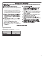
Specications
Capacity: Maximum dry load size which can be treated in a
cycle, as declared by the manufacturer.
Rated Voltage 120 V
Rated Frequency 60 Hz
Rated Current 12 A
Capacity 3.4 Kg (7.5 lb)

4
Installation Instructions
Tools and Parts
Tools needed
Gather the required tools and parts before starting installation.
Read and follow the instructions provided with tools listed below.
Flat-blade screwdriver Tin snips (new vent
installations)
Level Vent clamps
Adjustable wrench that opens
to 1" (25 mm) or hex-head
socket wrench
Caulking gun and compound
(for installing new exhaust vent)
Parts supplied
Remove parts package from the dryer drum. Check that all parts
listed are included.
Cycle control knob Start button
Leveling legs (4)
Alternate Parts: (Not supplied with dryer)
Your installation may require additional parts. To order, please
refer to “Assistance or Service” on the back cover. You may also
contact the dealer from whom you purchased your dryer.
Check local codes, existing electrical supply and venting, and
see “Venting Requirements” and “Electrical Requirements” before
purchasing parts.
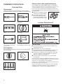
■ Mobile home installations require
metal exhaust system hardware.
■ For portable installations you
will need an optional portable
assembly kit, including 4 casters,
power cord brackets and screws.
Location Requirements
You will need
■ A location that allows for proper exhaust installation. See
“Venting Requirements.”
■ A 120 V, 60 Hz., AC only, 15 or 20 A circuit.
■ A grounded electrical outlet located within 2 ft. (610 mm) of
either side of the dryer. See “Electrical Requirements.”
■ A sturdy oor to support the dryer weight (dryer and load)
of 115 lbs (52 kg). The combined weight of a companion
appliance should also be considered.
■ A level oor with a maximum slope of 1" (25 mm) under
the entire dryer.
Do not operate your dryer at temperatures below 45ºF (7ºC). At
lower temperatures, the dryer might not shut off at the end of an
automatic cycle. Drying times can be extended.
The dryer must not be installed or stored in an area where it will
be exposed to water and/or weather.
Check code requirements. Some codes limit, or do not permit,
installation of the dryer in garages, closets, mobile homes, or
sleeping quarters. Contact your local building inspector.

5
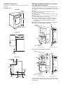
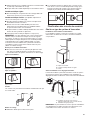
Installation Clearances
The location must be large enough to allow the dryer door to
open fully.
Dryer Dimensions
Front View
(606 mm)
1"
(25 mm)
23
7
/8"
(527 mm)
31"
(787
*20
3
/
4
"
mm)
Side View
1"
(25 mm)
36"
(914 mm)
(527 mm)
20
3
/4"
Back View
1"
(25 mm)
(600 mm
)
23
5
/8"
(210 mm
)
8
1
/4"
(83 mm)
3
1
/4"
(303 mm)
11
7
/8"
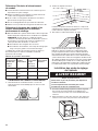
Minimum installation spacing for recessed
area and closet installation
The following dimensions shown are for the minimum spacing
allowed when the dryer is to be operated with, or without, the
Stack Stand Kit. To purchase a Stack Stand Kit, see “Assistance
or Service.”
■ Additional spacing should be considered for ease of
installation and servicing.
■ Additional clearances might be required for wall, door, and
oor moldings.
■ Additional spacing of 1" (25 mm) on all sides of the dryer is
recommended to reduce noise transfer.
■ For closet installation with a door, minimum ventilation
openings in the top and bottom of the door are required.
Louvered doors with equivalent ventilation openings
are acceptable.
■ Companion appliance spacing should also be considered.
Recessed or closet installation - Dryer only
(76 mm)
3"
(76 mm)
3"
24 in.
2
(155 cm
2
)
48 in.
2
(310 cm
2
)
(457 mm)
18"
(76 mm)
3"*
1"
(25 mm)
1"
(25 mm)
1"
(25 mm)
14"
(356 mm)
Recessed area Closet door with vents
Recessed or closet installation - Stacked
(76 mm)
3"
(76 mm)
3"
3"*
(76 mm)
24 in.
2
(155 cm
2
)
48 in.
2
(310 cm
2
)
1"
(25 mm)
(25 mm)
1"
1"
(25 mm)
12"
(305 mm)
12"
(305 mm)
Closet door with ventsRecessed area
DRYER
WASHER
*Most installations require a minimum 5½" (140 mm) clearance
behind the dryer for the exhaust vent with elbows. See “Venting
Requirements.”

6
Mobile Home - Additional Location Requirements
This dryer is suitable for mobile home installations.
The installation must conform to the Manufactured Home
Construction and Safety Standard, Title 24 CFR, Part 3280
(formerly the Federal Standard for Mobile Home Construction
and Safety, Title 245, HUD Part 280) or Standard CAN/CSA-Z240
MH.
Mobile home installations require:
■ Metal exhaust system hardware which is available for
purchase from your dealer.
■ Special provisions must be made in mobile homes to
introduce outside air into the dryer. The opening (such as a
nearby window) should be at least twice as large as the dryer
exhaust opening.
Electrical Requirements
■ 120 V, 60 Hz, AC only, 15 or 20 A fused electrical supply is
required.
■ A time-delay fuse or circuit breaker is recommended.
Check that the fuse or circuit breaker matches the rating
of your line.
■ It is also recommended that a separate circuit serving only for
this dryer is provided.
■ Do not use an extension cord.
GROUNDING INSTRUCTIONS
SAVE THESE INSTRUCTIONS
■
For a grounded, cord-connected dryer:
This dryer must be grounded. In the event of malfunction or
breakdown, grounding will reduce the risk of electric shock
by providing a path of least resistance for electric current.
This dryer is equipped with a cord having an equipment-
grounding conductor and a grounding plug. The plug must
be plugged into an appropriate outlet that is properly
installed and grounded in accordance with all local codes
and ordinances.
WARNING: Improper connection of the equipment-
grounding conductor can result in a risk of electric shock.
Check with a qualied electrician or service representative
or personnel if you are in doubt as to whether the dryer is
properly grounded. Do not modify the plug provided with
the dryer: if it will not t the outlet, have a proper outlet
installed by a qualied electrician.
Venting
Venting Requirements
WARNING: To reduce the risk of re, this dryer MUST BE
EXHAUSTED OUTDOORS.
IMPORTANT: Observe all governing codes and ordinances.
Dryer exhaust must not be connected into any gas vent, chimney,
wall, ceiling, attic, crawlspace, or a concealed space of a
building. Only rigid or exible metal vent shall be used
for exhausting.
4"
(102 mm)
4" (102 mm) heavy metal exhaust vent
■ Only a 4" (102 mm) heavy metal exhaust vent and clamps
may be used.
■ Do not use plastic or metal foil vent.
Rigid metal vent:
■ Recommended for best drying performance and to avoid
crushing and kinking.
Flexible metal vent:
(Acceptable only if it is accessible to clean)
■ Must be fully extended and supported in nal dryer location.
■ Remove excess to avoid sagging and kinking that may result
in reduced airow and poor performance.
■ Do not install in enclosed walls, ceilings, or oors.
■ The total length should not exceed 7¾ ft. (2.4 m).
NOTE: If using an existing vent system, clean lint from entire
length of the system and make sure exhaust hood is not plugged
with lint. Replace plastic or metal foil vents with rigid metal
or exible metal vents. Review “Vent System Chart” and, if
necessary, modify existing vent system to achieve best drying
performance.

7
Exhaust hoods:
■ Must be at least 12" (305 mm) from ground or any object
that may obstruct exhaust (such as owers, rocks, bushes,
or snow).
Recommended Style:
Louvered hood Box hood
Acceptable Style:
Angled hood
Elbows
45° elbows provide better airow than 90° elbows.
Good Better
Clamps
■ Use clamps to seal all joints.
■ Exhaust vent must not be connected or secured with screws
or other fastening devices that extend into the interior of the
duct, because they can catch lint. Do not use duct tape.
Plan Vent System
Choose your exhaust installation type
Recommended exhaust installations:
Typical installations vent the dryer from the rear of the dryer.
Other installations are possible.
A
B
C
A. Exhaust hood
B. Flexible metal or rigid metal vent
C. Elbow
Alternate installations for close clearances:
Venting systems come in many varieties. Select the best type
for your installation. Two close-clearance installations are shown
as below. For more information, refer to the manufacturer’s
instructions.
A B
A. Over-the-top installation
(also available with one offset elbow)
B. Periscope installation
NOTE: The kits for close clearance alternate installations
are available for purchase. For information on ordering, see
“Assistance or Service.”

8
Determine vent path
■ Select the route that will provide the straightest and most
direct path outdoors.
■ Plan the installation to use the fewest number of elbows
and turns.
■ When using elbows or making turns, allow as much room
as possible.
■ Bend vent gradually to avoid kinking.
■ Use the fewest 90° turns possible.
Determine vent length and elbows needed for
best drying performance
■ Use the “Vent System Chart” below to determine the type of
vent material and hood combinations acceptable to use.
NOTE: Do not use vent runs longer than those specied in
the Vent system chart. Exhaust systems longer than those
specied will:
■ Shorten the life of the dryer.
■ Reduce performance, resulting in longer drying times and
increased energy usage.
The “Vent System Chart” provides venting requirements that will
help to achieve the best drying performance.
Vent System Chart
Number of
90º turns or
elbows
Type of vent Box or
louvered
hoods
Angled
hoods
0 Rigid metal 36 ft (11 m) 26 ft (7.9 m)
1 Rigid metal 26 ft (7.9 m) 16 ft (4.9 m)
2 Rigid metal 16 ft (4.9 m) 6 ft (1.8 m)
Install Vent System
1. Before installing the vent system, be sure to remove the wire
exhaust guard that is located at the exhaust outlet.
2. Install exhaust hood.
12" min.
(305 mm)
12" min.
(305 mm)
Install exhaust hood and use caulking compound to seal
exterior wall opening around exhaust hood.
3. Connect vent to exhaust hood.
Vent must t inside exhaust hood. Secure vent to exhaust
hood with 4" (102 mm) clamp. Run vent to dryer location.
Use the straightest path possible. See “Determine vent path”
in “Plan Vent System.” Avoid 90º turns. Use clamps to seal
all joints. Do not use duct tape, screws, or other fastening
devices that extend into the interior of the vent to secure vent,
because they can catch lint.
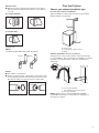
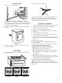
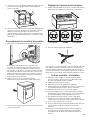
Install Leveling Legs
1. To avoid damaging oor, use a large at piece of cardboard
from dryer carton. Place cardboard under the entire back
edge of the dryer.
2. Firmly grasp dryer body and gently lay dryer on cardboard.
See illustration.
3. Start to screw legs into holes by hand. Use a wrench to nish
turning legs. They should stick out about 1" (25 mm).
4. Place a carton corner post from dryer packaging under each
of the 2 dryer back corners. Stand the dryer up. Slide the
dryer on the corner posts until it is close to its nal location.
Leave enough room to connect the exhaust vent.

9
Connect Vent
1. Connect vent to exhaust outlet.
Using a 4" (102 mm) clamp, connect the vent to exhaust
outlet in dryer. If connecting to existing vent, make sure the
vent is clean. Dryer vent must t over dryer exhaust outlet and
inside exhaust hood. Check that vent is secured to exhaust
hood with a 4" (102 mm) clamp.
2. Move dryer into its nal location. Avoid crushing or kinking
the vent.
3. Once the exhaust vent connection is made, remove corner
posts and cardboard.
Level Dryer
1. Check levelness of dryer. Check levelness rst side to side,
then front to back.
Not Level Not Level LEVEL
2. Tighten and adjust leveling legs.
If dryer is not level, prop the dryer up using a wood block. Use
a wrench to adjust the legs up or down and check again for
levelness. Once legs are level, make sure all four legs are snug
against the oor before tightening them.
Installation Checklist
1. Check that all parts are now installed. If there is an extra part,
go back through the steps to see what was skipped.
2. Check that you have all of your tools.
3. Dispose of/recycle all packaging materials.
4. Check dryer’s nal location. Be sure vent is not crushed or
kinked.
5. Check that dryer is on a level surface.
6. For power supply cord installation, plug into an outlet. For
direct wire installation, turn on power.
7. Remove lm on the console and any tape remaining on dryer.
Remove tape from lint screen (located on inside back wall of
dryer).
8. Read “Using Your Dryer.”
9. Wipe dryer drum interior thoroughly with a damp cloth to
remove any dust.
10. To test the dryer, set the dryer on a full heat cycle (not an air
cycle) for 20 minutes and start the dryer.
If the dryer will not start, check the following:
■ Controls are set in a running or “On” position.
■ START button has been rmly pressed.
■ Dryer is plugged into an outlet and/or electrical supply is on.
■ Household fuse is intact and tight, or circuit breaker has
not tripped.
■ Dryer door is closed.
11. When the dryer has been running for 5 minutes, open the
dryer door and feel for heat. If you feel heat, cancel cycle and
close the door. Your unit is now ready to use.
If you do not feel heat, check the following:
■ Controls are set on a heated cycle, not an air cycle.
NOTE: You may notice an odor when dryer is rst heated. This
odor is common when the heating element is rst used. The odor
will go away.

10
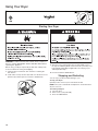
Using Your Dryer
Starting Your Dryer
WARNING: To reduce the risk of re, electric shock, or injury to
persons, read the IMPORTANT SAFETY INSTRUCTIONS before
operating this appliance.
Before using your dryer, wipe the dryer drum with a damp cloth
to remove dust from storing and shipping.
1. Clean the lint screen before each load. See “Cleaning the
Lint Screen.”
2. Load clothes loosely into the dryer and close the door. Do not
pack the dryer. Allow space for clothes to tumble freely.
3. Turn the Cycle Control knob to the recommended cycle for
the type of load being dried. Use the Normal cycle to dry most
heavyweight and medium weight loads. See “Drying, Cycle,
and Temperature Tips.”
4. Press the PUSH TO START button.
Stopping and Restarting
You can stop your dryer anytime during a cycle.
To stop your dryer:
Open dryer door or turn Cycle Control knob to OFF.
NOTE: The Cycle Control knob should point to an Off area when
dryer is not in use.
To restart your dryer:
1. Close the door.
2. Select a new cycle (if desired).
3. Press the START button.

11
Loading
Load clothes loosely into the dryer. Do not overload the dryer.
Allow space for clothes to tumble freely. The following chart
shows the maximum load you can place in your compact dryer.
Expect longer drying times.
Heavy work clothes 2 pair of pants, 3 work shirts
Delicates 1 camisole, 2 slips, 4 undergarments,
1 set of sleepwear, 1 half slip
Towels 9 bath towels; or 6 bath towels,
3hand towels, 6 washcloths
Mixed load 2 pillowcases, 1 T-shirt, 2 shirts,
1pair slacks
Knits 2 slacks, 2 shirts; or 3 dresses
Permanent Press 6 shirts; or 2 double sheets &
2pillowcases; or 2 singles sheets &
2pillowcases
Drying, Cycle, and Temperature Tips
Select the correct cycle and temperature for your load.
Your dryer tumbles the load without heat during the last few
minutes of all cycles to make the load easier to handle.
Drying tips
■ Follow care label directions when they are available.
■ If desired, add a fabric softener sheet. Follow package
instructions.
■ Remove load from the dryer as soon as tumbling stops to
reduce wrinkling. This is especially important for Normal, knits,
and synthetic fabrics.
Cycle and temperature tips
■ Dry most loads using the Normal cycle.
■ Use a no heat (air) setting for rubber, plastic, or heat-
sensitive fabrics.
■ Line-dry bonded or laminated fabrics.
NOTE: If you have questions about drying temperatures for
various loads, refer to the care label directions.
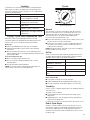
Cycles
Cycle Control knob
Normal
This automatic cycle shuts off the dryer when the selected
dryness is reached. The Cycle Control knob does not move
until the load is almost dry. After the cool down, the knob
automatically turns to an Off area and tumbling stops.
Dry most loads using the Normal cycle.
■ If the load is drier than you like, select a setting closer to Less
Dry the next time you dry a similar load.
■ If the load is not as dry as you like, complete drying using
Timed Dry. The next time you dry a similar load, select a
setting closer to More Dry.
NOTE: Drying time with an automatic cycle varies according to
the type of fabric and size of load.
Air Dry
Use this cycle for items that require drying without heat, such
as rubber, plastic and heat-sensitive fabrics. See the chart for
examples of items that can be dried using Air Dry.
Type of Load Time*
Foam rubber - pillows,
padded bras, stuffed toys
20 - 30
Plastic - shower curtains,
tablecloths
20 - 30
Rubber-backed rugs 40 - 50
Olen, polypropylene, sheer
nylon
10 - 20
*(Minutes). Reset cycle to complete drying, if needed.
When using Air Dry
■ Check that coverings are securely stitched.
■ Shake and uff pillows by hand periodically during cycle.
■ Dry item completely. Foam rubber pillows are slow to dry.
Timed Dry
Use this cycle to complete drying if items are still damp after the
automatic cycle.
Timed Dry is also useful for:
■ Heavyweight items and work clothes that require a long
drying time.
■ Lightweight items, such as lingerie, blouses and knits that
require a short drying time.
For damp dry, turn the Cycle Control knob to 30 minutes or less.
End of Cycle Signal
The dryer sounds a signal to let you know when the cycle is
nished. The signal is not adjustable and cannot be turned off.
The signal is helpful when you are drying permanent press,
synthetics and other items that should be taken out as soon as
the dryer stops.

12
Dryer Care
Cleaning the Dryer Location
Keep dryer area clear and free from items that would obstruct the
ow of combustion and ventilation air.
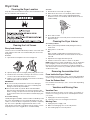
Cleaning the Lint Screen
Every load cleaning
The lint screen is located inside the dryer drum, on the back wall.
Clean it before each load. A screen blocked by lint can increase
drying time.
To clean:
1. Open the door and pull the lint screen straight out.
2. Squeeze body of lint screen lightly while pulling off the cover.
3. Roll lint off the screen with your ngers. Do not rinse or wash
screen to remove lint. Wet lint is hard to remove.
4. Replace cover on lint screen body. Push the lint screen rmly
back into place and close the door.
IMPORTANT:
■ Do not run the dryer with the lint screen loose, damaged,
blocked, or missing. Doing so can cause overheating and
damage to both the dryer and fabrics.
■ Some towels made of synthetic bers and natural bers
(polyester and cotton blends) may shed more lint than other
towels, causing your dryer’s lint screen to ll up faster. Be sure
to remove lint from the lint screen before and after drying new
towels.
As needed cleaning
Laundry detergent and fabric softener residue can build up on the
lint screen. This buildup can cause longer drying times for your
clothes, or cause the dryer to stop before your load is completely
dry. The screen is probably clogged if lint falls off the screen.
Clean the lint screen with a nylon brush every 6 months, or more
frequently if it becomes clogged due to a residue buildup.
To wash:
1. Roll lint off the screen with your ngers.
2. Wet both the lint screen cover and body with hot water.
3. Wet a nylon brush with hot water and liquid detergent.
Scrub lint screen cover and body with the brush to remove
residue buildup.
4. Rinse with hot water.
5. Thoroughly dry lint screen body and cover with a clean towel.
Replace in dryer.
Cleaning the Dryer Interior
To clean dryer drum:
1. Make a paste with powdered laundry detergent and very
warm water.
2. Apply paste to a soft cloth.
OR
Apply a liquid, nonammable household cleaner to the
stained area and rub with a soft cloth until all excess dye is
removed.
3. Wipe drum thoroughly with a damp cloth.
4. Tumble a load of clean clothes or towels to dry drum.
NOTE: Garments that contain unstable dyes, such as denim blue
jeans or brightly colored cotton items, may discolor the dryer
interior. These stains are not harmful to your dryer and will not
stain future loads of clothes. Dry unstable dye items inside-out to
avoid transfer of dye.
Removing Accumulated Lint
From Inside the Dryer Cabinet
Lint should be removed every 2 years, or more often, depending
on dryer usage. Cleaning should be done by a qualied person.
From the Exhaust Vent
Lint should be removed every 2 years, or more often, depending
on dryer usage.
Vacation and Moving Care
Vacation Care
Operate your dryer only when you are at home. If you will be on
vacation or not using your dryer for an extended period of time,
you should:
1. Unplug dryer or disconnect power.
2. Clean lint screen. See “Cleaning the Lint Screen.”
Moving Care
1. Unplug the power supply cord.
2. Make sure leveling legs are secure in dryer base.
3. Use masking tape to secure dryer door.

13
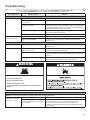
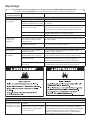
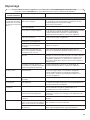
Troubleshooting
If you experience Possible Causes Solution
Dryer Operation
Dryer will not run Door not closed completely. Make sure the dryer door is closed completely.
Press and hold the START button
2–5 seconds.
Press and hold the START button 2–5 seconds.
Household fuse is blown or circuit
breaker has tripped.
There should be a household fuse or circuit breaker for the dryer.
Check that the fuse is intact and tight, or that the circuit breaker
has not tripped. Replace the fuse or reset the circuit breaker. If
the problem continues, call an electrician.
Incorrect power supply. Electric dryers require 120 V power supply.
Check with a qualied electrician.
Wrong type of fuse. Use a time-delay fuse.
Timer does not
noticeably advance
Dryer set to Timed or Air Dry. The timer moves slowly and continuously for the time setting.
Dryer set to Normal Dry. The timer moves only when the clothing is mostly dry. See
“Normal Cycle.”
Unusual Noise
Thumping noise Dryer hasn’t been used in a while. This is normal. The thumping sound should diminish after a few
minutes of use.
Rattling or vibrating noise A small object caught between the
edges of dryer drum.
Check the front and rear edges of the drum for small objects.
Clean out pockets before laundering.
Dryer isn’t properly leveled. The dryer may vibrate if not properly installed. Check the
levelness of the dryer. All four feet should be in rm contact with
the oor.
Clothing is balled up in dryer. When balled up, the load will bounce, causing the dryer to
vibrate. Separate the load items and restart the dryer.
First try the solutions suggested here or visit our website at www.whirlpool.com/product_help -
In Canada www.whirlpool.ca for assistance and to possibly avoid a service call.
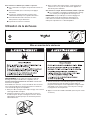
WARNING
Fire Hazard
Use a heavy metal vent.
Do not use a plastic vent.
Do not use a metal foil vent.
Failure to follow these instructions can result in death
or fire.
Dryer Results
NOTE: The compact dryer operates at a lower wattage. Expect longer drying times.
Clothes are not drying
satisfactorily or drying
times are too long
Lint screen is clogged with lint. Clean lint screen before each load.
The exhaust vent or outside exhaust
hood is clogged with lint, restricting
air movement.
Run the dryer for 5–10 minutes. Hold your hand under
the outside exhaust hood to check air movement. If you
do not feel air movement, clean exhaust system of lint
or replace exhaust vent with heavy metal or exible metal vent.
See “Venting.”

14
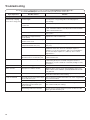
Troubleshooting
If you experience Possible Causes Solution
Dryer Results
Clothes are not drying
satisfactorily or drying
times are too long (cont.)
The exhaust vent is not the
correct length.
Check that the exhaust vent is not too long or has
too many turns. Long venting will increase drying times.
See “Venting.”
The exhaust vent diameter is not the
correct size.
Use 4" (102 mm) diameter vent material.
The dryer is not level. Clothes not contacting the moisture sensors during Automatic
cycles. Check the levelness of the dryer. All four feet should be
in rm contact with the oor.
The Air Dry Cycle has been selected. Select the correct Cycle for the types of garments being dried.
See “Cycles.”
The load is too large and heavy
to dry quickly.
Separate the load to tumble freely.
Fabric softener sheets are blocking
the lint screen cover.
Use only one fabric softener sheet, and use it only once.
The dryer is located in a room with
temperature below 45ºF (7ºC).
Proper operation of dryer cycles requires temperatures above
45ºF (7ºC).
The dryer is located in a closet. Closet doors must have ventilation openings at the top
and bottom of the door. The front of the dryer requires a
minimum of 1" (25 mm) of airspace, and, for most installations,
the rear of the dryer requires 5½" (140 mm). See “Location
Requirements.”
The load may not be contacting the
Moisture Sensors on Normal Cycles.
Check the levelness of the dryer. All four feet should be in rm
contact with the oor.
Cycle time is too short The Normal cycle is ending early. Change the dryness level setting on Normal cycles. Increasing
or decreasing the dryness level will change the amount of
drying time in a cycle. If loads are consistently ending too early,
see “Cycles.”
Lint on load Lint screen is clogged with lint. Clean lint screen before each load.
Stains on load Improper use of fabric softener. Add dryer fabric softener sheets at the beginning of the cycle.
Fabric softener sheets added to a partially dried load can stain
your garments.
Stains on drum Loose dyes in clothes. Drum stains are caused by dyes in clothing (usually blue jeans).
These will not transfer to other clothing.
Loads are wrinkled The load was not removed from dryer
at the end of the cycle.
Refer to garment care label instructions. Dry clean only garments
are not recommended.
The dryer was tightly packed. Dry smaller loads that can tumble freely.
Odors Recent painting, staining, or
varnishing in the area where your
dryer is located.
Ventilate the area. When the odors or fumes are gone from the
area, rewash and dry the clothing.
Dryer being used for the rst time. The new electric heating element may have an odor. The odor
will be gone after the rst cycle.
First try the solutions suggested here or visit our website at www.whirlpool.com/product_help -
In Canada www.whirlpool.ca for assistance and to possibly avoid a service call.

15
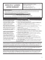
WHIRLPOOL
®
LAUNDRY
LIMITED WARRANTY
ATTACH YOUR RECEIPT HERE. PROOF OF PURCHASE IS
REQUIRED TO OBTAIN WARRANTY SERVICE.
Please have the following information available when you call the
Customer eXperience Center:
n
Name, address, and telephone number
n
Model number and serial number
n
A clear, detailed description of the problem
n
Proof of purchase including dealer or retailer name and address
DISCLAIMER OF IMPLIED WARRANTIES
IMPLIED WARRANTIES, INCLUDING ANY IMPLIED WARRANTY OF MERCHANTABILITY OR IMPLIED WARRANTY OF FITNESS FOR
A PARTICULAR PURPOSE, ARE LIMITED TO ONE YEAR OR THE SHORTEST PERIOD ALLOWED BY LAW. Some states and provinces
do not allow limitations on the duration of implied warranties of merchantability or tness, so this limitation may not apply to you. This
warranty gives you specic legal rights, and you also may have other rights that vary from state to state or province to province.
LIMITATION OF REMEDIES; EXCLUSION OF INCIDENTAL AND CONSEQUENTIAL DAMAGES
YOUR SOLE AND EXCLUSIVE REMEDY UNDER THIS LIMITED WARRANTY SHALL BE PRODUCT REPAIR AS PROVIDED HEREIN.
WHIRLPOOL SHALL NOT BE LIABLE FOR INCIDENTAL OR CONSEQUENTIAL DAMAGES. Some states and provinces do not allow
the exclusion or limitation of incidental or consequential damages, so these limitations and exclusions may not apply to you. This
warranty gives you specic legal rights, and you also may have other rights that vary from state to state or province to province.
DISCLAIMER OF REPRESENTATIONS OUTSIDE OF WARRANTY
Whirlpool makes no representations about the quality, durability, or need for service or repair of this major appliance other than the
representations contained in this Warranty. If you want a longer or more comprehensive warranty than the limited warranty that comes
with this major appliance, you should ask Whirlpool or your retailer about buying an extended warranty.
10/17
IF YOU NEED SERVICE:
1. Before contacting us to arrange service, please determine whether your product requires repair. Some questions can be
addressed without service. Please take a few minutes to review the Troubleshooting section of the Use and Care Guide
or visit the “HOW-TOS & FAQS” section of https://www.whirlpool.com/owners.html.
2. All warranty service is provided exclusively by our authorized Whirlpool Service Providers.
In the U.S. and Canada, direct all requests for warranty service to:
Whirlpool Customer eXperience Center
In the U.S.A. call 1-866-698-2538. In Canada call 1-800-807-6777.
If outside the 50 United States and Canada, contact your authorized Whirlpool dealer to determine if another warranty applies.
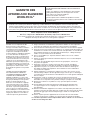
ONE YEAR LIMITED WARRANTY
WHAT IS COVERED
WHAT IS NOT COVERED
1. Commercial, non-residential, multiple-family use, or use inconsistent with published
user, operator, or installation instructions.
2. In-home instruction on how to use your product.
3. Service to correct improper product maintenance or installation, installation not in
accordance with electrical or plumbing codes, or correction of household electrical
or plumbing (e.g., house wiring, fuses, or water inlet hoses).
4. Consumable parts (e.g., light bulbs, batteries, air or water lters, preservation
solutions).
5.
Defects or damage caused by the use of non-genuine Whirlpool parts or accessories.
6. Conversion of your product from natural gas or propane gas or reversal
of appliance doors.
7. Damage from accident, misuse, abuse, re, oods, acts of God, or use with
products not approved by Whirlpool.
8. Repairs to parts or systems to correct product damage or defects caused by
unauthorized service, alteration, or modication of the appliance.
9. Cosmetic damage including scratches, dents, chips, and other damage to appliance
nishes unless such damage results from defects in materials and workmanship and
is reported to Whirlpool within 30 days.
10. Discoloration, rust, or oxidation of surfaces resulting from caustic or corrosive
environments, including but not limited to, high salt concentrations, high moisture
or humidity, or exposure to chemicals.
11. Pick-up or delivery. This product is intended for in-home repair.
12. Travel or transportation expenses for service in remote locations where an
authorized Whirlpool servicer is not available.
13. Removal or reinstallation of inaccessible appliances or built-in xtures (e.g., trim,
decorative panels, ooring, cabinetry, islands, countertops, drywall) that interfere
with servicing, removal, or replacement of the product.
14. Service or parts for appliances with original model/serial numbers removed, altered,
or not easily determined.
The cost of repair or replacement under these excluded circumstances shall be
borne by the customer.
For one year from the date of purchase,
when this major appliance is installed,
operated, and maintained according
to instructions attached to or furnished
with the product, Whirlpool Corporation
or Whirlpool Canada LP (hereafter
“Whirlpool”) will pay for Factory
Specified Replacement Parts and repair
labor to correct defects in materials or
workmanship that existed when this major
appliance was purchased, or at its sole
discretion replace the product. In the event
of product replacement, your appliance
will be warranted by the remaining term of
the original unit’s warranty period.
YOUR SOLE AND EXCLUSIVE REMEDY
UNDER THIS LIMITED WARRANTY
SHALL BE PRODUCT REPAIR AS
PROVIDED HEREIN. Service must be
provided by a Whirlpool designated
service company. This limited warranty
is valid only in the United States or
Canada and applies only when the major
appliance is used in the country in which
it was purchased. This limited warranty
is effective from the date of original
consumer purchase. Proof of original
purchase date is required to obtain service
under this limited warranty.

16
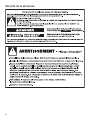
Sécurité de la sécheuse

17
Pour réduire le risqued'incendiedû à des charges
contaminées, la partie nale du programme de séchage
par culbutage a lieu sans chaleur (période de refroidissement).
Éviterd’arrêterunesécheuseen phase de culbutageavant la
n du programme de séchage, à moins de
retireretd’étendrerapidementtous les articles an que la
chaleur se dissipe.
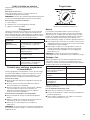
Spécications
Capacité: Taille de la charge maximale à sécher selon
le fabricant.
Tension nominale 120V
Fréquence nominale 60Hz
Courant nominal 12 A
Capacité 3,4kg (7,5lb)

18
Instructions d’installation
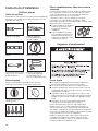
Outils et pièces
Outils nécessaires
Rassembler les outils et pièces nécessaires avant d’entreprendre
l’installation. Lire et observer les instructions fournies avec les
outils de la liste suivante.
Tournevis à tête plate Cisaille de ferblantier
(pourl’installation d’un
nouveau conduit)
Niveau Brides de conduit
Clé à molette avec ouverture
jusqu’à 1" (25mm) ou clé à
douille hexagonale
Pistolet à calfeutrage et
composé de calfeutrage
(pourl’installation d’un
nouveau conduit d’évacuation)
Pièces fournies
Retirer le sachet de pièces du tambour de la sécheuse.
Vérierque toutes les pièces énumérées sont présentes.
Bouton de commande
desprogrammes
Bouton Start (mise en marche)
Pieds de nivellement (4)
Pièces supplémentaires: (Non fourni avec la
sécheuse)
Il se peut que l’installation nécessite des pièces supplémentaires.
Pour commander, consulter la section “Assistance ou service”
sur la couverture arrière. Il est aussi possible de contacter le
marchand chez qui la sécheuse a été achetée.
Consulter les codes locaux, les “Exigences concernant
l’évacuation” et les “Spécications électriques”, vérier
l’alimentation électrique et le circuit d’évacuation existants, avant
d’acheter les pièces nécessaires.
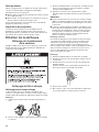
■ Pour les installations en résidence
mobile, le circuit d’évacuation
nécessite des matériaux
métalliques.
■ Pour les installations portatives,
vous aurez besoin d’une trousse
portative optionnelle qui inclue
4 roulettes, des brides de cordon
d’alimentation et des vis.
Exigences d’emplacement
Il vous faudra
■ Un emplacement permettant une évacuation appropriée.
Voirla section “Exigences concernant l’évacuation”.
■ Un circuit de 120 V CA à 60Hz et 15 ou 20A seulement.
■ Une prise électrique avec liaison à la terre située à moins de
2pi (610mm) de l’un des côtés de la sécheuse. Consulter les
“Spécications électriques”.
■ Un plancher robuste qui peut supporter une sécheuse d’un
poids total (sécheuse et charge) de 115lb (52kg). Il faut aussi
prendre en compte le poids combiné d’un appareil ménager
voisin.
■ Un plancher de niveau ayant une pente maximale de
1 po (25 mm) sous l’ensemble de la sécheuse.
Ne pas faire fonctionner la sécheuse à des températures
inférieures à 45°F (7°C). À des températures inférieures, la
sécheuse risque de ne pas s’arrêter à la n d’un programme
automatique. Les durées de séchage risquent alors d’augmenter.
La sécheuse ne doit pas être installée ou remisée dans un endroit
où elle sera exposée à l’eau ou aux intempéries.
Vérier les spécications des codes. Certains codes limitent
ou interdisent l’installation des sécheuses dans un garage,
un placard, une résidence mobile ou une chambre à coucher.
Contacter l’inspecteur en bâtiments local.

19
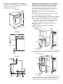
Distances de dégagement à respecter
L’emplacement doit être assez grand pour permettre d’ouvrir
complètement la porte de la sécheuse.
Dimensions de la sécheuse
Vue de face
(606 mm)
1"
(25 mm)
23
7
/8"
(527 mm)
31"
(787
*20
3
/
4
"
mm)
Vue latérale
1"
(25 mm)
36"
(914 mm)
(527 mm)
20
3
/4"
Vue arrière
1"
(25 mm)
(600 mm
)
23
5
/8"
(210 mm
)
8
1
/4"
(83 mm)
3
1
/4"
(303 mm)
11
7
/8"
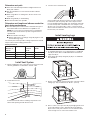
Espacement minimum pour une installation
dans un encastrement et dans un placard
Les dimensions suivantes indiquent l’espacement minimum
autorisé lorsque la sécheuse doit être utilisée avec ou sans
nécessaire de superposition. Pour acheter un nécessaire de
superposition, voir la section “Assistance ou service”.
■ Prévoir davantage d’espace pour faciliter l’installation et
l’entretien.
■ Un espace supplémentaire peut être requis pour les moulures
de porte et de plancher et pour les plinthes.
■ Un espace supplémentaire de 1" (25 mm) de tous les côtés de
la sécheuse est recommandé pour réduire le transfert du bruit.
■ Pour installation dans un placard avec porte, on doit prévoir
des ouvertures minimums d’entrée d’air en haut et en bas
de la porte. Les portes à claire-voie offrant des ouvertures
équivalentes de passage de l’air sont acceptables.
■ Il faut aussi prendre en compte l’espace requis entre les
appareils voisins.
Installation dans un encastrement ou un placard –
sécheuseseulement
(76 mm)
3"
(76 mm)
3"
24 po.
2
(155 cm
2
)
48 po.
2
(310 cm
2
)
(457 mm)
18"
(76 mm)
3"*
1"
(25 mm)
1"
(25 mm)
1"
(25 mm)
14"
(356 mm)
Encastrement Porte de placard avec grille d’aération
Installation dans un encastrement ou un placard – superposition
(76 mm)
3"
(76 mm)
3"
3"*
(76 mm)
24 po.
2
(155 cm
2
)
48 po.
2
(310 cm
2
)
1"
(25 mm)
(25 mm)
1"
1"
(25 mm)
12"
(305 mm)
12"
(305 mm)
SÉCHEUSE
LAVEUSE
Encastrement Porte de placard avec grille d’aération
* La plupart des installations requièrent un espace minimum de 5½"
(140 mm) derrière la sécheuse pour le conduit d’évacuation avec
coudes. Voir la section “Exigences concernant l’évacuation”.

20
Maison mobile – Exigences d’emplacement supplémentaires
Cette sécheuse peut être installée dans une maison mobile.
L’installation doit satisfaire les critères de la Manufactured Home
Construction and Safety Standard, Titre 24 CFR, partie 3280
(anciennement Federal Standard for Mobile Home Construction
and Safety, Titre 245 HUD, partie 280) ou de la Norme CAN/CSA-
Z240MH.
Critères à respecter pour une installation dans une maison
mobile :
■ Un système d’évacuation en métal qui peut être acheté chez
votre marchand.
■ Il faut prendre des dispositions spéciales dans les maisons
mobiles pour l’apport d’air de l’extérieur dans la sécheuse.
L’ouverture (telle qu’une fenêtre à proximité) devrait être au
moins deux fois plus grande que l’ouverture de décharge de la
sécheuse.
Spécications électriques
AVERTISSEMENT
Risque de choc électrique
Brancher sur une prise à 3 alvéoles reliée à la terre.
Ne pas enlever la broche de liaison à la terre.
Ne pas utiliser un adaptateur.
Ne pas utiliser un câble de rallonge.
Le non-respect de ces instructions peut causer
un décès, un incendie ou un choc électrique.
■ Une source d’alimentation de 120 V CA à 60Hz uniquement et
protégée par fusible de 15 ou 20A est nécessaire.
■ On recommande d’utiliser un fusible ou un disjoncteur
temporisé.
Vérier que le fusible ou le disjoncteur correspond aux
caractéristiques de la ligne électrique.
■ Il est également recommandé de raccorder l’appareil sur un
circuit distinct exclusif à cet appareil.
■ Ne pas utiliser de rallonge.
Pour une sécheuse reliée à la terre et connectée par
un cordon :
Cette sécheuse doit être reliée à la terre. En cas de mauvais
fonctionnement ou de panne, la liaison à la terre réduira le
risque de choc électrique en offrant au courant électrique un
acheminement d'évacuation de moindre résistance. Cette
sécheuse est alimentée par un cordon électrique comportant
un conducteur relié à la terre et une che de branchement
munie d'une broche de liaison à la terre. La che doit être
branchée sur une prise appropriée qui est bien installée et
reliée à la terre conformément à tous les codes et règlements
locaux.
INSTRUCTIONS DE LIAISON À LA TERRE
CONSERVEZ CES INSTRUCTIONS
AVERTISSEMENT :
Le raccordement incorrect de
cet appareil au conducteur de liaison à la terre peut susciter
un risque de choc électrique. En cas de doute quant à la
qualité de liaison à la terre de la sécheuse, consulter un
électricien ou un technicien ou un personnel qualié. Ne pas
modier la che de branchement fournie avec la sécheuse;
si la che ne correspond pas à la conguration de la prise de
courant, demander à un électricien qualié d'installer une
prise de courant appropriée.
Évacuation
Exigences concernant l’évacuation
AVERTISSEMENT: Pour réduire le risque d’incendie,
cette sécheuse doit ÉVACUER L’AIR À L’EXTÉRIEUR.
IMPORTANT: Observer les dispositions de tous les codes et
règlements en vigueur.
Le conduit d’évacuation de la sécheuse ne doit pas être raccordé
à une évacuation de gaz, une cheminée, un mur, un plafond,
un grenier, un vide sanitaire ou un vide de construction. Seul un
conduit d’évacuation métallique rigide ou souple doit être utilisé
pour le système d’évacuation.
4"
(102 mm)
Conduit d’évacuation en métal lourd de 4" (102mm)
La page est en cours de chargement...
La page est en cours de chargement...
La page est en cours de chargement...
La page est en cours de chargement...
La page est en cours de chargement...
La page est en cours de chargement...
La page est en cours de chargement...
La page est en cours de chargement...
La page est en cours de chargement...
La page est en cours de chargement...
La page est en cours de chargement...
La page est en cours de chargement...
-
 1
1
-
 2
2
-
 3
3
-
 4
4
-
 5
5
-
 6
6
-
 7
7
-
 8
8
-
 9
9
-
 10
10
-
 11
11
-
 12
12
-
 13
13
-
 14
14
-
 15
15
-
 16
16
-
 17
17
-
 18
18
-
 19
19
-
 20
20
-
 21
21
-
 22
22
-
 23
23
-
 24
24
-
 25
25
-
 26
26
-
 27
27
-
 28
28
-
 29
29
-
 30
30
-
 31
31
-
 32
32


Whirlpool LDR3822PQ Manuel utilisateur
- Catégorie
- Sèche-linge
- Taper
- Manuel utilisateur
dans d''autres langues
- English: Whirlpool LDR3822PQ User manual
Documents connexes
-
Whirlpool YGEW9200LW1 Mode d'emploi
-
Whirlpool LDR3822PQ Manuel utilisateur
-
-
-
-
-
Whirlpool WHD560CHW Warranty
-
Whirlpool WED8620HC Warranty
-
-
Whirlpool WED5620HW Warranty