Goal Zero HPP+ Solar Wall Plate Mode d'emploi
- Taper
- Mode d'emploi

HPP+ SOLAR WALL PLATE
INSTALLATION GUIDE
Gang Box
Not Included

Getting Started 4
i. In the Box 4
Installation Instructions 6
Français 10
Connecteur Verrouillage femelle HPP+
Fils d’alimentation 10AWG
Fils de données 18AWG
Courant nominal 40A
Dimensions de la plaque 9,96 x 5,00 x 0,15cm
(3,92 x 1,97 x 0,05po)
Garantie 2ans
Certifications RoHS, REACH, Prop 65, UL1977
Table of Contents
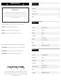
Spécifications
Please read all warnings, instructions and cautions carefully before use to avoid personal injury, property
damage or damage to your Yeti PRO 4000, or any connected products. Goal Zero reserves the right to update
this document without prior notice. Please visit www.goalzero.com to find the latest product information and
the most recent version of the User Guide.
IMPORTANT SAFETY INSTRUCTIONS
SAVE THESE INSTRUCTIONS
For assistance with your device in the United States, visit our contact page at www.goalzero.com/contact or call
1-888-794-6250. For assistance with your device outside of the United States, contact the local distributor.
If you do not have contact information for the local distributor, contact us in the United States and we will help
connect you to the local representative.
INSTRUCTIONS RELATIVES AU RISQUE D’INCENDIE, DE CHOC ÉLECTRIQUE OU DE BLESSURE.
• AVERTISSEMENT– Haute tension. Le système peut comporter des tensions allant jusqu’à 150V.
• AVERTISSEMENT– Ce connecteur doit être utilisé uniquement avec les produits Goal Zero.
• AVERTISSEMENT– Ce produit doit être installé par un électricien qualifié et agréé.
INSTRUCTIONS PERTAINING TO RISK OF FIRE, ELECTRIC SHOCK, OR INJURY TO PERSONS.
• WARNING - High Voltage. System may include voltages up to 150 V.
• WARNING - This connector should only be used with Goal Zero Products.
• WARNING - This product must be installed by a qualified and licensed electrician.
Connector Female Locking HPP+
Power Wires 10 AWG
Data Wires 18 AWG
Current Rating 40 A
Plate Dims 3.92 x 1.97 x 0.05in
(9.96 x 5.00 x 0.15cm)
Warranty 2 years
Certifications RoHS, REACH, Prop 65, UL1977
Specifications

4 5
In the Box
1. 2x HPP+ Solar Wall Plugs
2. 1x Interior Outlet Cover
3. 2x Mounting screws for the interior outlet cover
4. 2x RJ45 couplers
Additional Items Needed for Installation (Not Included)
1. Outdoor Outlet Cover
2. 2x Gang Outlet Box
3. Internal Wall Cable for solar (10 AWG, 90C rated)
*Note: We recommend using different colored cables for positive and negative.
4. CAT5e or CAT6 cable
5. RJ45 male connectors
6. Wing-Nut Wire Connectors
7. Goal Zero Solar Solution (eg. Nomad 400)
8. Goal Zero Male to Male 12′ HPP + Extension Cable, SKU 98710
9. Goal Zero Yeti PRO 4000
10. Goal Zero Tank PRO 4000 expansion tank(s) (optional)
11. Goal Zero Haven 10 manual transfer switch (optional)
1
2
4
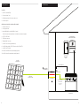
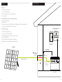
Install Overview
Getting Started
Haven 10
Goal Zero
Solar Solution
Home Circuit
Panel
Goal Zero Haven 10
Manual Transfer Switch
Yeti PRO 4000
HPP Solar
Extension Cable
Male to Male 12′ HPP +
Extension Cable
Sold Separately
SKU 98710
Exterior HPP+
Solar Wall Plugs
Interior Outlet
12 ft max distance
Solar -
Solar +
RS485 Bus

6 7
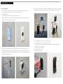
How to Install the Wall Plate
1. Choose a location to install your wall plate indoors. It should be within 12 feet of where you’ll be storing your
Yeti power station. For assistance choosing the best location, consult your electrician.
2. Electrical box preparation
a. If using an existing box: Follow the industry standards for running wires.
b. If using a new box: Choose a location for your outdoor wall plate. Be sure it is within reach of your desired solar
location. Install the box according to industry standards.
3. Run the solar cables through the wall between the exterior and interior outlets. Then run the Cat5e/Cat6 cable.
If installing via conduit, please ensure the solar wiring is in a different conduit run from the Cat5e/Cat6, per NEC
requirements. If running cables internally, make sure there is at least 6 inches of space between the high voltage solar
cable and low voltage Cat5e/Cat6 cable.
Installation Instructions
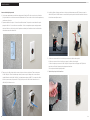
4. Install exterior and interior electrical boxes according to required NEC standards. Make sure the Cat5e/Cat6 and
10 AWG wiring enter and exit the box from different entry points to provide high voltage/low voltage isolation.
5. a. Use a Wing-Nut Wire Connector to connect the positive solar cables.
b. Use a Wing-Nut Wire Connector to connect the negative solar cables
c. Use Coupler to connect the internal wall Cat5e/Cat6 cable to the interior wall plate Cat5e/Cat6 using the
coupler. Repeat for the exterior wall plate.
d. Screw the wall plug into the wall plate.
6. Repeat step 4 for the outdoor box.

8 9
10. Connect solar. For your safety, the solar panels should always be the last thing connected to reduce risk of
exposure to live voltages.
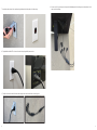
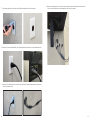
7. Attach the outdoor plate for the outdoor plug. And attach the indoor plate to the indoor plug.
8. Plug the Male-to-Male HPP+ Connector into the indoor plug and Yeti power station.
9. Plug all solar extension cables from the outdoor plug to the solar location before connecting solar.

10 11
Dans la boîte
1. 2x Fiches murales solaires HPP
2. 1x Couvercle de prise intérieure
3. 2x vis de montage pour le couvercle de la prise intérieure
4. 2x CoupleursRJ45
Articles supplémentaires nécessaires à l’installation (non inclus)
1. Couvercle de prise extérieure
2. 2x Boîte de sortie
3. Câble mural interne pour le solaire (10AWG, classé 90C) *Remarque: Nous vous recommandons d’utiliser
descâbles de couleur différente pour le positif et le négatif.
4. CâbleCAT5e ou CAT6
5. Connecteurs mâlesRJ45
6. Connecteurs de fils à écrou à oreilles
7. Solution solaire Goal Zero (ex. Nomad400)
8. Goal Zero Mâle à mâle 12pi HPP + câble de rallonge, UGS98710
9. Goal Zero Yeti PRO 4000
10. Réservoir d’expansion Goal Zero Tank PRO 4000 (optionnel)
11. Commutateur de transfert manuel Goal Zero Haven10 (optionnel)
1
2
4
Haven 10
Solution solaire
Goal Zero
Panneau de circuit
domestique
Commutateur de transfert manuel
Goal Zero Haven10
Yeti PRO4000
Câble d’extension HPP Solar
Mâle-mâle 12pi HPP + Câble
derallonge
Vendu séparément
UGS98710
Fiches murales
solaires HPP+
pour l’extérieur Sortie intérieure
Distance maximale
de 3,65m (12p)
Solaire -
Solaire +
Bus RS485
Mise en route Aperçu de l’installation

12 13
Comment installer la plaque murale
1. Choisissez un emplacement pour installer votre plaque murale à l’intérieur. Elle doit se trouver à moins de 3mètres
(12pi) de l’endroit où vous stockerez votre station d’alimentation Yeti. Pour vous aider à choisir le meilleur emplacement,
consultez votre électricien.
2. Préparation du boîtier électrique a. Si vous utilisez un boîtier existant: Respectez les normes industrielles pour le
passage des câbles. b. Si vous utilisez un nouveau boîtier: Choisissez un emplacement pour votre plaque murale
extérieure. Veillez à ce qu’elle soit à portée de l’emplacement souhaité pour l’installation solaire. Installez le boîtier
conformément aux normes industrielles.
3. Faites passer les câbles solaires dans le mur entre les prises extérieures et intérieures. Faites ensuite passer
le câbleCat5e/Cat6. En cas d’installation par conduit, assurez-vous que le câblage solaire se trouve dans un
conduitdifférent de celui du câbleCat5e/Cat6, conformément aux exigences du NEC. Si vous passez les câbles
àl’intérieur, assurez-vous qu’il y a au moins 15cm (6po) d’espace entre le câble solaire à haute tension et le
câbleCat5e/Cat6àbasse tension.
4. Installez les boîtiers électriques extérieurs et intérieurs conformément aux normes NEC. Assurez-vous que les
câbles Cat5e/Cat6 et 10AWG entrent et sortent de la boîte par des points d’entrée différents afin de fournir une
isolation haute tension/basse tension.
5. a. Utilisez un connecteur de fil à écrou à oreilles pour connecter les câbles solaires positifs.
b. Utilisez un connecteur à écrou à oreilles pour connecter les câbles solaires négatifs.
c. Utilisez le coupleur pour connecter le câbleCat5e/Cat6 de la paroi intérieure à la plaqueCat5e/Cat6 de la
paroi intérieure. Répétez l’opération pour la plaque murale extérieure.
d. Vissez la prise murale dans la plaque murale.
6. Répétez l’étape4 pour le boîtier extérieur.
Guide d’installation

14 15
7. Fixez la plaque extérieure à la prise extérieure. Et fixez la plaque intérieure à la prise intérieure.
8. Branchez le connecteur mâle-mâle HPP+ dans la fiche d’alimentation intérieure et la station d’alimentation Yeti.
9. Branchez tous les câbles d’extension solaire de la prise extérieure à l’emplacement du panneau solaire avant de
connecter le panneau solaire.
10. Branchez les panneaux solaires. Pour votre sécurité, les panneaux solaires doivent toujours être les derniers
àêtreconnectés afin de réduire le risque d’exposition à des tensions électriques.

REV B
GOAL ZERO HEADQUARTERS
Draper, UT 84020
1-888-794-6250
Designed in the U.S.A.
Made in China
Goal Zero Yeti is a trademark of Goal Zero.
-
 1
1
-
 2
2
-
 3
3
-
 4
4
-
 5
5
-
 6
6
-
 7
7
-
 8
8
-
 9
9


Goal Zero HPP+ Solar Wall Plate Mode d'emploi
- Taper
- Mode d'emploi
dans d''autres langues
Documents connexes
-
Goal Zero HPP Guide d'installation
-
Goal Zero Haven 10 Quick Start Guide Mode d'emploi
-
Goal Zero Boulder 100i Mode d'emploi
-
-
-
-
Goal Zero Yeti 1250 Mode d'emploi
-
-
-
Goal Zero Yeti 150 Le manuel du propriétaire