itAM electronic TS-12vr Manuel utilisateur
- Taper
- Manuel utilisateur

12/ 24 Volt
Full Multi Norm
DE, PL, EC, EU, EI, UK
CB-Mobilfunkgerät
CB Mobile Radio
Transmisor móvil CB
Cb émetteur récepteur
CB Ricetrasmettitori
CB mobile zender
Bedienungsanleitung
Operating Instruction
Manual de Instrucción
Manuale d’istruzioni
Mode d’emploi
Handleiding
REPEATER
TS-12vr
TS-12vr
Deutsch
English
Español
Italiano
Français
Nederlands
man_ts-12vr_1_RoadCOM manual.qxd 05.08.2022 16:00 Seite 1

3
15
7
10
4
14
1 Micrófono con cable rizado y
conector 6 pin
2 Botón pulsar para hablar [ PTT ]
3 Indicador LED
4 Selección de modulación [ AM/FM ]
5 Botón de selector canal abajo [ q]
6 Botón de selector canal arriba [ p]
7 Botón de Squelch automático [ ASQ ]
8 Interruptor de Squelch manual [ SQ ]
9 Control de volumen, Encendido/
Apagado
10 Sensibilidad de la señal de
recepción [ RF-Gain ]
11 Botón de prioridad canal 9 / 19
[ EMG] & Repeater Mode
12 RX/TX control LED
13 AM/FM control LED
14 ASQ control LED
15 Conector de micrófono 6 pin
16 Conector de antena aéreo
SO239
17 Cable de alimentación DC
18 Conector Jack ( 3,5 mm ) para
altavoces externos
19 Botón de selector canal abajo [ q]
20 Botón de selector canal arriba [ p]
21 Modo VOX
Español página 24 - 29 Netherland pagina 42 - 47
1 Microfoon met spiraal kabel
en 6 pin plug
2 Push to talk toets [ PTT ]
3 LED display
4 Omschakelen van de
modulatie [ AM/FM ]
5 Kanaal selectie omhoog [ q]
6 Kanaal selectie omlaag [ p]
7 automatische squelch [ ASQ ]
8 Squelch bediening [ SQ ]
9 Volume bediening, Aan/Uit
schakelaar [ Off / Vol ]
10 [ RF-GAIN ]
11 Kanaal 9 / 19 priority toets
[ EMG ] & Repeater Mode
12 RX / TX LED
13 AM/FM LED
14 ASQ LED
15 Microfoon aansluiting 6 pin
16 Antenne aansluiting SO239
17 DC kabel
18 Jack aansluiting ( 3.5 mm )
voor externe luidspreker
19 Kanaal selectie omhoog [ q]
20 Kanaal selectie omlaag [ p]
21 VOX
1 Mikrofon mit Spiralkabel +
6-Pol Stecker
2 Sendetaste [ PTT ]
3 LED-Kanalanzeige
4 Modulationsart [ AM/FM ]
5 Kanalwahlschalter runter [ q]
6 Kanalwahlschalter hoch [ p]
7 automatische Rauschsperre [ ASQ ]
8 manuelle Rauschsperre [ SQ ]
9 Lautstärkeregler / Ein-/Ausschalter
10 Empfangssignal-Empfindlichkeit
[ RF GAIN ]
11 Vorrangkanaltaste für Kanal 9/19
[ EMG ] & Repeater Mode
12 LED Send-/Empfangsanzeige
[ RX/TX ]
13 LED Betriebsartanzeige AM / FM
14 LED ASQ
15 6 Pol-Mikrofonanschlussbuchse
16 Antennenanschlussbuchse SO239
17 Stromversorgungskabel
18 Anschlussbuchse für externen
Lautsprecher 3,5 mm
19 Kanalwahlschalter runter [ q]
20 Kanalwahlschalter hoch [ p]
21 VOX Modus-Schalter
Deutsch Seite 4 - 10
1 Microfono con cavo
spiralizzato e spina a 6 Pin
2 Tasto PTT [ PTT ]
3 Display LED
4 Selezione modalità [ AM/FM ]
5 Tasto selettore canale DN [ q]
6 Tasto selettore canale UP [ p]
7 Regolazione Squelch
automatico [ ASQ ]
8 Regolazione Squelch [ SQ ]
9 Regolazione volume +
interruttore ON/OFF
10 [ RF-Gain ]
11 Tasto di canale 9 / 19 prioritario
[ EMG ] & Repeater Mode
12 RX / TX LED
13 AM/FM LED
14 ASQ LED
15 Presa microfono a 6 Pin
16 Connettore SO239
17 Cavo alimentatore
18 Jack (3,5 mm.) per
altoparlante esterno
19 Tasto selettore canale DN [ q]
20 Tasto selettore canale UP [ p]
21 VOX
Italiano página 30 - 35
1 Microphone avec câble torsadé
et fiche 6 broches
2 Touche d'émission [ PTT ]
3 Afficheur du type LED
4 Touche de commutation du fonctionne-
ment AM/FM [ AM/FM ]
5 Touche de sélection de canaux
vers le bas [ q]
6 Touche de sélection de canaux
vers le haut [ p]
7 Touche du squelch automatique [ ASQ ]
8 Réglage et marche/arrêt du squelch [SQ]
9 Réglage du volume et marche / arrêt
10 [ RF-Gain ] & Repeater Mode
11 Touche canal 9 / 19 prioritaire [ EMG ]
12 RX / TX LED
13 AM/FM LED
14 ASQ LED
15 Prise du microphone 6 broches
16 Connecteur d'antenne SO239
17 Câble d'alimentation
18 Prise jack ( 3,5 mm ) pour un
haut-parleur externe
19 Touche de sélection de canaux [ q]
20 Touche de sélection de canaux [ p]
21 VOX
Français page 36- 41
1 Microphone with curled cable
and 6 pin plug
2 Push to talk key [ PTT ]
3 LED display
4 Modulation [ AM/FM ]
5 channel selector down [ q]
6 channel selector up [ p]
7 automatic squelch [ ASQ ]
8 manual squelch [ SQ ]
9 volume control / On/Off switch
10 Receiving Signal Sensitivity
[ RF-GAIN ]
11 Channel 9 / 19 priority key
[ EMG ] & Repeater Mode
12 LED Indication
[ RX/TX ]
13 LED Indication AM / FM
14 LED ASQ
15 microphone jack,6-pin
16 aerial connector SO239
17 DC power cable
18 Jack socket ( 3.5 mm ) for
external speaker
19 channel selector down [ q]
20 channel selector up [ p]
21 VOX Mode Switch
English page 12 - 17
59
11 12 13 6
1
16
18
17
19 20
222
21
8
TS-12vr
man_ts-12vr_1_RoadCOM manual.qxd 05.08.2022 16:00 Seite 2

Deutsch
Inbetriebnahme des TEAM TS-12vr
1) Montage einer CB-Funkantenne
Die Wahl der Antenne und des Montageortes ist von großer Bedeutung für die maximale
Reichweite Ihrer Funkanlage. Die folgenden Kriterien sollten Sie bei der Wahl des Anten-
nenstandortes und der Montage berücksichtigen.
Allgemein gilt:
> Die Antenne muss für den Funkbetrieb auf 27 MHz geeignet sein.
> Der Standort der Antenne sollte möglichst hoch und unverbaut sein.
> Das Antennenkabel muss unbeschädigt, und die Stecker ordnungsgemäß angeschlossen
sein.
> Das Antennenkabel darf nicht zu stark geknickt werden.
> Antennen mit einer größeren mechanischen Länge erzielen bessere Reichweiten.
Bei der Montage von Mobilantennen ist folgendes zu beachten:
> Die Antenne sollte in der Mitte eines größeren Karosserieteils montiert werden.
> Der Antennenfuß von Mobilantennen sollte möglichst guten Kontakt zu einer metallisch gut
leitenden Fläche des Karosseriebleches haben.
Außer der "festen Montage" einer Mobilantenne, bei der ein Loch in die Karosserie Ihres Fahr-
zeuges gebohrt werden muss, gibt es noch weitere Möglichkeiten, z. B. die Dachrinnen- oder
Kofferraumdeckel-Montage, sowie die Befestigung mit Magnetfuß oder Scheibenantenne.
2) Antennenanschluss
Der PL-Stecker (Typ PL259) des Antennenkabels (Koaxialkabel) wird mit der Buchse (15) an
der Geräterückseite verbunden. Für eine einwandfreie Verbindung muss der Überwurf des
Steckers gut festgedreht werden. Ebenso ist auf eine ordentliche Verbindung des Antennen-
kabels mit dem Antennenfuß zu achten. Nicht einwandfreie Verbindungen können zu einem
Defekt des Gerätes führen und die Funkreichweite erheblich verringern. Die Antennenanlage
(nicht im Lieferumfang enthalten) sollte sehr gut an das Funkgerät angepasst sein, ansonsten
wird ein Teil der Sendeleistung an der Antenne reflektiert und nicht abgestrahlt. Das führt
ebenfalls zu einer geringeren Reichweite der Funkanlage. Die Anpassung der Antenne erfolgt
durch Längenabgleich des Antennenstrahlers bzw. seiner Anpassungsvorrichtung auf ein
minimales Stehwellenverhältnis, welches mit einem Stehwellenmessgerät (z.B. TEAM SWR
1180 -) gemessen werden kann. Das Stehwellenmessgerät muss nach der Messung wieder
aus der Antennenleitung entfernt werden.
3) Montage des Gerätes im Fahrzeug
Das Gerät kann mit dem beiliegenden Montagebügel-Set z.B. unter dem Armaturenbrett
befestigt werden. Bei der Wahl der optimalen Position für die Montage des Gerätes in Ihrem
Fahrzeug sind auch die folgenden Kriterien zu berücksichtigen:
> keine Beeinträchtigung der Verkehrssicherheit,
> gute Erreichbarkeit der Bedienelemente,
> ausreichende Luftzirkulation, um eine Überhitzung des Gerätes im Sendefall zu verhindern.
Deutsch
INHALTSVERZEICHNIS
Inbetriebnahme des TEAM TS-12vr
1) Montage einer CB-Funkantenne 5
2) Antennenanschluss 5
3) Montage des Gerätes im Fahrzeug 5 - 6
4) Mikrofon 6
5) Stromversorgung 6
Funkbetrieb mit dem TEAM TS-12vr
1) Einschalten [ Off / Vol ]7
2) Rauschsperre [ SQ / ASQ ]7
3) Kanalwahl [ q] [ p]7
4) Umschaltung der Modulationsarten [ AM/FM ] 7 - 8
5) Umschaltung der Normen 8
6) Senden 8
7) Vorrangkanal 9/19 [ EMG ] 8
8) RF-Gain Empfangsempfindlichkeit 8-9
9) Repeatermodus 9
10) Anschlussbuchse für einen externen Zusatzlautsprecher 9
Hinweise
1) Sicherheitshinweis 10
2) Allgemeine Hinweise 10
3) Service 10
4) Konformität 10
5) Entsorgung 10
Frequenztabelle 42
Technische Daten 43
4 5
man_ts-12vr_1_RoadCOM manual.qxd 05.08.2022 16:00 Seite 4

Funkbetrieb mit dem TEAM TS-12vr
1) Einschalten [ Off / Vol ]
Zum Einschalten des Gerätes, den Lautstärkeregler ( 9 ) [ Off / Vol ] nach rechts drehen.
Um die Lautstärke optimal anzupassen, sollte der Rauschsperreregler ( 8 ) [ SQ ] fast bis zum
Linksanschlag gedreht werden, bis ein Rauschen ertönt. Stellen Sie nun die gewünschte Lau-
stärke ein.
Alle Einstellungen, die beim Betrieb des Gerätes vorgenommen werden, bleiben nach dem
Ausschalten erhalten.
2) Rauschsperre [ SQ ] und [ ASQ ]
Das störende, andauernde Rauschen, das immer auf freien Kanälen auftritt, kann mit Hilfe der
Rauschsperre unterdrückt werden. Das Gerät vefügt über eine automatische (ASQ) und eine
manuelle Rauschsperre (SQ).
Die automatische Rauschunterdrückung ist intern auf einen fixierten Mittelwert eingestellt und
wird durch Drehenn des Rauschsperrendruckknopfes bis Links Anschlag ( 8 ) [ ASQ ] aktiviert.
In der LED Anzeige (14) wird der aktivierte Zustand der automatischen Rauschsperre bestätigt.
Die Einstellungen des ASQ Werts erfolgt durch längeres Drück der RFG Taste(10). Im Dispaly
(3) erscheint der Wert von A1 - A5. Durch drücken der UP/DOWN Taste kann dieser Wert ver-
ändert werden. Mit A1 wird der Empfänger am empfindlichsten und bei A5 ist er am unemp-
findlichsten.
Zum Einstellen der manuellen Rauschunterdrückung, drehen Sie bitte den Rauschsperreregler
( 8 ) zuerst ganz nach links, bevor sie dann den Regler langsam nach rechts drehen und somit
die Empfindlichkeit erhöhen. Der Regler sollte nur soweit über den Stummschaltepunkt gedreht
werden, bis das Rauschen sicher unterdrückt ist. Wenn eine Station auf dem Kanal sendet, öff-
net die Rauschsperre, und das Signal ist hörbar. Bei zu kritischer Einstellung der Rauschsperre
kann ab und zu ein kurzes Rauschen auftreten, ohne dass sich eine Station auf dem Kanal
befindet. Weiteres Rechtsdrehen unterdrückt zunehmend schwache Stationen, aber auch stär-
kere Störsignale.
3) Kanalwahl [ qCH ] [ pCH ]
Die Kanäle können durch Drücken der Kanalwahltasten ( 5 ) [ qCH ] und ( 6 ) [ pCH ] eingestellt
werden. In der LED Anzeige ( 3 ) wird die Kanalnummer dargestellt. Während des Sendens kann
kein anderer Kanal eingestellt werden. Die Kanalnummern werden ringförmig durchlaufen, so
dass die Kanäle abwärts zählend von 1 auf 40 bzw. 80, und aufwärts zählend von 80 bzw. 40
auf 1 übergangslos gewählt werden können. Es kann nur auf übereinstimmenden Kanalnum-
mern und Modulationsarten mit der Gegenstation Funkbetrieb aufgenommen werden.
4) Umschaltung der Modulationsarten [ AM/FM ]
Das TS-12vr arbeitet in den Modulationsarten AM und FM. Falls das Gerät auf dem aktuellen
Kanal auch die Betriebsart AM akzeptiert, können Sie es durch Drücken der Taste (4)
[ AM/FM ] zwischen AM und FM hin- und herschalten. Die gewählte Betriebsart AM wird in
der LED (13) angezeigt. Falls Sie sich auf einem Kanal in der Betriebsart AM befinden und
auf einen Kanal wechseln, auf dem die Betriebsart AM nicht akzeptiert wird, erfolgt eine
Zwangsumschaltung auf FM. Bei einem weiteren Wechsel auf einen Kanal, auf dem die
Betriebsart AM wieder akzeptiert wird, springt die Betriebsart automatisch wieder auf AM
zurück.
Darüber hinaus sollten Sie auch sicherstellen, dass die LED-Kanalanzeige ( 3 ) gut ablesbar
ist. Bei direkter Sonneneinstrahlung kann die Lesbarkeit der Anzeige beeinträchtigt werden.
Die günstigste Montageposition sollte vor dem endgültigen Einbau überprüft werden. Mit Hilfe
des beiliegenden Montagebügels, ist eine schnelle Montage bzw. Demontage an verschiede-
nen Stellen im Fahrzeug möglich.
4) Mikrofon
Im Lieferumfang enthalten ist das VOX Mikrofon DM-6006X, welches den neuen gesetzlichen
Bestimmungen bezüglich der notwendigen Verwendung von Freisprecheinrichtungen im Fahr-
betrieb entspricht. Die VOX Funktion (Voice Operated Transmission) ermöglicht das sprach-
gesteuerte Senden ohne nötige Bedienung der PTT Sendetaste. Wahlweise kann hiermit zwi-
schen dem VOX Betrieb und dem PTT Betrieb umgeschaltet werden.
VOX-Empfindlichkeit
Die Einstellung VOX-Empfindlichkeit bestimmt ab welcher Signalstärke der automatische
Sendemodus startet. Es stehen 4 Stufen zur Verfügung.
Langes Drücken der Taste [ q] ( 20 ) aktiviert die Einstellung der VOX-Empfindlichkeit,
bestätigt durch einen langen Ton und dem Aufleuchten der LED.
Kurzes Drücken der Taste wechselt zur nächst höheren Empfindlichkeitsstufe. Die 4 verfügbaren
Stufen sind durch die Anzahl der Bestätigungstöne gekennzeichnet. Für die höchste Stufe wäh-
len Sie die Stufe 1 (ein Ton ist zu hören). Eine Bestätigung der Einstellung ist nicht nötig.
VOX-Verzögerung
Die Einstellung VOX-Verzögerung bestimmt die Verweildauer im VOX-Sendemodus nach dem
Signalende. Es stehen 4 Einstellungen zur Verfügung.
Langes Drücken der Taste [ p] ( 19 ) aktiviert die Einstellung der VOX-Verzögerungszeit.
bestätigt durch einen langen Ton und dem Aufleuchten der LED.
Kurzes Drücken der Taste wechselt zur nächst längeren Verweildauer. Die 4 verfügbaren Stu-
fen sind durch die Anzahl der Bestätigungstöne gekennzeichnet. Für die höchste Stufe wäh-
len Sie die Stufe 1 (ein Ton ist zu hören). Eine Bestätigung der Einstellung ist nicht nötig.
Das Mikrofon wird mit dem 6-poligen Stecker in die Mikrofonbuchse (15) an der linken Gerä-
tefrontseite angeschlossen. Ohne Mikrofon ist kein Sende- oder Empfangsbetrieb möglich.
5) Stromversorgung
Vor dem Anschluss der Stromversorgung schalten Sie das Gerät aus, indem Sie den Laut-
stärkeregler ( 9 ) [ Off / Vol ] bis zum Einrasten nach links drehen.
Verbinden Sie die beiden blanken Anschlüsse am Ende des Kabels mit dem 12 V oder
24 V Bordnetz Ihres Fahrzeuges. Das Stromversorgungskabel sollte möglichst weit von stö-
renden Aggregaten verlegt werden. Achten Sie beim Anschluss auf die richtige Polarität:
SCHWARZ wird mit "-" ( = MINUS / Masse ) des KFZ verbunden.
ROT wird mit "12 Volt +" ( = PLUS ) des KFZ/LKW-Bordnetzes verbunden.
Bei Verwendung von Dauerplus bleiben die letzten Einstellungen auch nach dem Ausschal-
ten des Gerätes und dem Abstellen des Motors gespeichert.
Nachdem die Antenne, das Mikrofon und die Stromversorgung sorgfältig angeschlossen sind,
kann der Funkbetrieb aufgenommen werden.
Deutsch Deutsch
6 7
man_ts-12vr_1_RoadCOM manual.qxd 05.08.2022 16:00 Seite 6

Zur Einstellung des HF-Verstärkers (RF GAIN) wird die Taste RFG nur kurz betätigt. Es
erscheint r0 bis r7. Durch drücken der UP/DOWN Taste kann dieser Wert verändert werden.
R0 ist die höchste Verstärkung und bei r7 ist die HF-Verstärkung am geringsten.
9) Repeatermodus
Der Repeatemodus ist für den Funkbetrieb über eine Funkrelaisstation erforderlich, um auf
unterschiedlichen Kanäle zu senden und zu empfangen. Der Repeatermodus wird wie folgt
eingestellt:
a) Gerät ist im ausgeschalteten Zustand
b) Die Tasten EMG (11) und zur gleichen Zeit die Sendetaste (2) am Mikrofon(1) festhalten
und das Gerät einschalten.
c) Es blinken im Wechsel der Empfangskanal und das Zeichen „r“.
d) Jetzt kann mit den up/down Tasten (am Gerät oder am Mikrofon) der Empfangskanal
eingestellt werden.
e) Durch Drücken der Taste EMG (11) wird der Sendekanal ausgewählt. Es blinken im
Wechsel der Sendekanal und das Zeichen „t“.
f) Jetzt kann mit den up/down Tasten (am Gerät oder am Mikrofon) der Sendekanal einge
stellt werden.
g) Durch langes Drücken der Taste EMG (11) gelangt man in den voreingestellten Repeater
Modus. Das Gerät zeigt „r“ im Display (3) an. Zum Verlassen des Modus die Taste EMG
(11) erneut lang drücken.
10) Anschlussbuchse für einen externen Zusatzlautsprecher
Das TS-12vr hat an der Geräterückseite eine Klinkenbuchse (18) 3,5 mm ø zum Anschluss
für einen externen Lautsprecher mit 4 - 8 Ohm Impedanz (z.B. TEAM TS-500). Bei Anschluss
des externen Lautsprechers wird der interne Lautsprecher abgeschaltet.
Bei 4 Ohm sollte die Belastbarkeit des Lautsprechers 4 Watt betragen.
DeutschDeutsch
8 9
Hinweis für die Norm UK:
In der Norm UK wird nur die Betriebsart FM angezeigt. Durch Drücken des AM/FM-Schalters
(7) wird zwischen den FM-Frequenzbändern EC oder UK umgeschaltet. Die Norm UK verfügt
über 40 Kanäle FM UK (27,60125 - 27,99125 MHz) und 40 Kanäle FM EC (26,965 - 27,405
MHz).
5) Umschaltung der Normen
Die Geräteversion "TS-12vr Multi Norm" kann vom Benutzer auf eine der folgenden Normen
eingestellt werden:
Norm Kanäle und Frequenzen Anzeige
DE 80 FM (26,565 - 27,405 MHz), 4 W / 40 AM (26,965 - 27,405 MHz), 4 W DE
UK 40 FM (27,60125 - 27,99125 MHz), 4 W / 40 FM (26,965 - 27,405 MHz), 4 W UK
EI 40 FM (26,965 - 27,405 MHz), 4 W / 40 AM (26,965 - 27,405 MHz), 4 W EI
EU 40 FM (26,965 - 27,405 MHz), 4 W / 40 AM (26,965 - 27,405 MHz), 1 W EU
EC 40 FM (26,965 - 27,405 MHz), 4 W EC
PL 40 FM (26,960 - 27,400 MHz), 4 W / 40 AM (26,960 - 27,400 MHz), 4 W PL
Zum Einstellen bzw. Umschalten der Normen halten Sie bitte den Kanalwahl ( 6 ) [ q] und
die Sendetaste ( 2 ) [ PTT ] während dem Einschalten des Gerätes gedrückt. In der Anzeige
erscheint das Kürzel der aktuellen Norm. Alle anderen Symbole sind nicht sichtbar. Die
gewünschte Norm wird mit Hilfe der Kanalwahltasten (19 / 20) eingestellt. Zum Bestätigen
der Norm das Gerät kurz aus- und wieder einschalten oder die PTT ( 2 ) erneut drücken.
Für die Erlaubnis und die Auflagen zum Betrieb der verschiedenen Normen in den ein-
zelnen Ländern sehen Sie in den Gerätepass. Der Benutzer ist für die richtige Einstel-
lung der gültigen Norm im jeweiligen Land eigenverantwortlich.
6) Senden
Zum Senden wird die im Mikrofon (1) eingebaute Sendetaste (2) gedrückt und für die Dauer der
Durchsage gehalten. In dieser Zeit leuchtet das Sendekontroll-LED (12) . Sprechen Sie in das
Mikrofon aus ca. 5 cm Entfernung mit normaler Lautstärke. Zu lautes oder zu leises Bespre-
chen vermindert die Signalqualität. Nach Beendigung der Durchsage die Sprechtaste (2) los-
lassen. Das Gerät schaltet automatisch in den Empfangsbetrieb zurück.
7) Vorrangkanal 9 / 19 [ EMG ]
Das Gerät verfügt über die Vorrangkanäle 9 und 19. Durch kurzes einmaliges Drücken der
Vorrangkanaltaste ( 11 ) [ EMG ] wird Kanal 9 eingestellt. Zum Einstellen von Kanal 19, die
Vorrangkanaltaste zwei Mal kurz Drücken.
8) Empfangsempfindlichkeit [RF Gain]
Signale, die aus unmittelbarer Nähe empfangen werden, können unter Umständen zu stark sein,
das Signal klingt verzerrt. Mit der RF-Gain Funktion kann das Empfangssignal abgeschwächt
werden. Mit der Taste [RFGn] (10) wird die Empfangssignalstärke reduziert durch Schwä-
chung der Empfangsempfindlichkeit. Die aktivierte Empfangsempfindlichkeit wird in der LED
angezeigt.
man_ts-12vr_1_RoadCOM manual.qxd 05.08.2022 16:00 Seite 8

Deutsch Deutsch
11
HINWEISE
1) Sicherheitshinweis
Bitte beachten Sie als KFZ-Fahrer beim Funkbetrieb auch die Bestimmungen der jeweils gülti-
gen Straßenverkehrsordnung. Bei dem Betrieb des Gerätes wird Hochfrequenzenergie freige-
setzt. Es muss daher ein entsprechender Sicherheitsabstand zur Antenne eingehalten werden.
2) Allgemeine Hinweise
Das Gerät ist vor Feuchtigkeit und Staub zu schützen. Das Gerät niemals an Orten aufbe-
wahren, die einer starken Erhitzung und/oder direkter Sonneneinstrahlung ausgesetzt sein
könnten. Zur Gehäusereinigung ein weiches, fusselfreies Tuch verwenden. Zur Reinigung
niemals Lösungsmittel verwenden.
3) Service
Das Gerät darf nicht geöffnet werden. Eigenhändige Reparaturen oder Abgleich sind nicht
vorzunehmen, denn jede Veränderung, bzw. Fremdabgleich, können zum Erlöschen der
Betriebserlaubnis sowie der Gewährleistungs- und Reparaturansprüche führen. Bei Betriebs-
störungen sollte das Gerät nicht benutzt werden. Trennen Sie in diesem Fall die Stromver-
sorgung ab. Liegt ein Defekt vor, sollte auf jeden Fall der autorisierte TEAM-Fachhändler kon-
taktiert werden.
4) Konformität
Das CB-Mobilsprechfunkgerät TEAM TS-12vr entspricht der europäischen RED Direktive
2014/53/EU und hält die europäischen Normen EN 300 433, EN 489-1/-13, EN 60950-1 und
EN 62311 ein. Die genauen Länderbestimmungen der verschiedenen Versionen entnehmen
Sie bitte dem beiliegenden Gerätepass.
5) Entsorgung
Bitte werfen Sie Ihr TEAM-Altgerät nicht einfach auf den Müll, sondern senden Sie Ihr Altgerät
bitte portofrei zur fachgerechten Entsorgung an TEAM ein. TEAM wird anschließend die
umweltschonende Entsorgung Ihres Altgerätes für Sie kostenlos veranlassen. Bitte machen
Sie mit - der Umwelt zuliebe.
- Änderung der technischen Daten und der Ausführung sind ohne Vorankündigung vorbehalten. -
10
man_ts-12vr_1_RoadCOM manual.qxd 05.08.2022 16:00 Seite 10

English English
Setting up the TEAM TS-12vr
1) Installation of a CB antenna
The antenna is one of the most critical parts in the setup. The type of antenna and its location
has a great effect on the range of operation. Please consider the following criteria for selec-
tion of the best location and installation of your antenna:
> Make sure that the antenna is designed for radio operation on 27 MHz.
> The location of the antenna should be as high as possible without any obstacles nearby.
> The aerial cable should not be damaged and the plugs should be properly connected.
> Make sure that the antenna cable is not bent.
When you install a mobile antenna please note the following advices:
> The antenna should be fixed in the center of a big body-part, e.g. the trunk.
> The mobile antenna coil should have the closest possible contact with a conducting metallic
surface of the bodywork of the car.
There are also some other possibilities to fix the antenna onto the car without the necessity
to drill a hole into the bodywork of your car, e.g. mounting the antenna onto the gutter, mount-
ing the antenna onto a holder on the cover of the boot or using an antenna with a magnetic
foot or using a windscreen antenna.
2) Aerial Connection
Before pressing the transmit key, a suitable aerial must be connected. The PL259 plug of the
aerial cable ( coax ) is connected to the SO239 socket ( 13 ) on the rear panel. Make sure,
that all plugs are firmly tightened and properly soldered. Insufficient connections can damage
the radio and will reduce the range of operation.
The antenna should be matched with the radio, otherwise a part of the transmit power will be
reflected at the antenna and will not be radiated. This reduces the range of operation. The
matching of antenna to radio, is performed by a length adjustment of the antenna radial in
aim for a minimal SWR ratio which can be measured by a SWR meter,e.g. TEAM SWR
1180P. After the measurement the SWR meter should be removed from the antenna line.
3) Installation in the car
When you want to fix the unit in your car, you can either fasten it with the help of the included
mounting bracket below the dashboard. Always mount the transceiver where the switches are
easily accessible. Other important points to consider for a correct mounting position are:
> no interference of the roadworthiness,
> good access to the controls of the car,
> sufficient air circulation to prevent overheating of the radio in transmit mode.
Please consider the angle of view onto the display while driving. From a certain angle of view,
the readability of the display diminishes. An intensive solar irradiation can also affect the rea-
dability of the display. So it is recommended to check the best position before the final instal-
lation. The unit can easily be fixed onto different positions in the car by using the enclosed
mounting bracket.
TABLE OF CONTENTS
Setting up the TEAM TS-12vr
1) Installation of a CB antenna 13
2) Aerial Connection 13
3) Installation in the car 13
4) Microphone 14
5) Power source 14
Operation of the TEAM TS-12vr
1) Switching on [ Off / Vol ] 15
2) Squelch [ SQ / ASQ ] 15
3) Channel selection [ q] [ p]15
4) Modulation selection [ AM/FM ]15
5) Norm selection 16
6) Transmitting 16
7) Priotitiy Channels 9 / 19 16
8) RF-Gain 16
9) Repeater Modus 17
10) External speaker jack 17
Additional Information
1) Safety Instructions 17
2) General Precautions 17
3) Servicing 17
4) Conformity 17
Frequency Table 42
12 13
man_ts-12vr_1_RoadCOM manual.qxd 05.08.2022 16:00 Seite 12

4) Microphone
The VOX microphone DM-6006X is included in the scope of delivery, which complies with the
new legal regulations regarding the necessary use of hands-free devices while driving. The
VOX function (Voice Operated Transmission) enables voice-controlled transmission without
the need to operate the PTT transmit button. It can be used to switch between VOX mode
and PTT mode.
VOX sensitivity
The VOX sensitivity setting determines the signal strength at which the automatic transmis-
sion mode starts. There are 4 levels available.
A long press on the [ q] ( 20 ) key activates the VOX sensitivity setting, confirmed by a long
tone and the LED lighting up.
Pressing the button briefly switches to the next higher sensitivity level. The 4 available levels
are indicated by the number of confirmation beeps. For the highest level, select level 1 (a tone
is heard). It is not necessary to confirm the setting.
VOX delay
The VOX delay setting determines the dwell time in VOX transmit mode after the signal ends.
There are 4 settings available.
A long press on the [ p] key ( 19 ) activates the VOX delay setting. confirmed by a long tone
and the LED lighting up.
Pressing the button briefly switches to the next longer dwell time. The 4 available levels are
indicated by the number of confirmation beeps. For the highest level, select level 1 (a tone is
heard). Confirmation of the setting is not necessary.
The microphone is connected with the 6-pin plug into the microphone socket (15) on the left
front of the unit. No transmitting or receiving operation is possible without the microphone.
5) Power source
Before connecting the unit to a suitable power source via the fused DC power cable (15), the
device must be switched off by turning the volume control ( 9 ) [ Off / Vol ] counterclockwise
to the very end until a clicking sound is heard.
Then, connect the two naked leads at the end of the cable with the supply voltage of the
car/lorry battery. The unit is designed to operate with 12 volts or 24 volts and a negative
ground electrical system. Lay the cable as far as possible away from aggregates which can
cause interference. Watch for the correct polarity during the connection.
BLACK connect to - MINUS / ground of the car battery.
RED connect to 12 volts + PLUS of the car/lorry battery.
If the power source is not disconnected after putting the engine off, the last settings will
remain stored, after the unit and the car are switched off.
After proper connection of the microphone, the aerial and power source, radio operation can
be started.
Operation of the TEAM TS-12vr
1) Switching on [ Off / Vol ]
To turn on the radio, turn the On / Off switch (9) [ Off / Vol ] clockwise.
With the help of the squelch control (8) you can set a comfortable volume level. Set the manual
squelch (SQ) to a level where the constant noise of an empty channel is audible - see paragraph
2) Squelch. Now, adjust the volume level. The memory function stores the last settings, i.e.
norm, frequency band and channel after turning the radio off and on again.
2) Squelch [ SQ / ASQ ]
The annoying, persistent noise that always occurs on free channels can be suppressed with
the help of the squelch function. The unit has an automatic squelch (ASQ) and a manual
squelch (SQ).
The automatic squelch is internally set to a fixed average value and is activated by turning
the squelch push button to the left stop ( 8 ) [ ASQ ]. The LED display (14) confirms the acti-
vated state of the automatic squelch.The ASQ value is set by pressing and holding the RFG
button (10). The display (3) shows the value from A1 - A5. This value can be changed by
pressing the UP/DOWN key. A1 makes the receiver most sensitive and A5 makes it least sen-
sitive.
To adjust the manual noise reduction, first turn the squelch control ( 8 ) all the way to the left,
then slowly turn the control to the right to increase the sensitivity. The control should only be
turned so far above the mute point until the noise is safely suppressed. When a station is
transmitting on the channel, the squelch opens and the signal is audible. If the squelch is set
too critically, a short noise may occur from time to time without a station being on the channel.
Further turning to the right suppresses increasingly weak stations, but also stronger interfer-
ing signals.
3) Channel selection [ q] [ p]
All channels can be selected by pushing the channel selector keys (5) [ qCH ] and (6) [ pCH ]
located on the front panel of the radio. The selected channel is displayed on the LED (3). No
channel selection is possible while the radio is in transmission mode. The channels are
arranged in a consecutive order, in a ring-like-system, i.e. after the highest channel number it
starts again with channel no. 1 and vice versa. For communication with a partner CB station,
both transceivers must be adjusted to the same channel and the same modulation type.
4) Modulation selection [ AM/FM ]
For the TS-12vr, the operating modes AM and FM are available. The selected modulation type
is indicated by the LED (13). To toggle between the modes press the mode key (4) [ AM/FM ].
If the selected norm does not accept the modulation type AM on the actual channel, it will
remain on the modulation type FM.
If the radio is set to AM on the actual channel, and you select another channel, on which the
AM mode is inhibited, the modulation changes automatically to FM mode. If you select once
more another channel, on which the AM mode is allowed again, the modulation switches auto-
matically to back to AM mode.
band.
English English
14 15
man_ts-12vr_1_RoadCOM manual.qxd 05.08.2022 16:00 Seite 14

With norm UK in the version TS-12vr Full Multi Norm, you toggle between the EC band and
the UK band, which are indicated by the symbols EC and UK, by pressing the mode key (7)
[ AM/FM ]. The CB band EU consists of the 40 CEPT channels. The CB band UK consists of
40 channels starting from 27.60125 MHz to 27.99125 MHz.
After turning the radio off, the TS-12vr stores the last channel and the frequency
5) Norm Selection
The version TS-12vr Full Multi Norm can be set by the user to the following norms:
DE 80 FM
(26.565 - 27.405 MHz), 4 W / 40 AM (26.965 - 27.405 MHz), 4 W
EU 40 FM (26.965 - 27.405 MHz), 4 W / 40 AM (26.965 - 27.405 MHz), 1 W
EC 40 FM (26.965 - 27.405 MHz), 4 W
UK 40 FM (27.60125 - 27.99125 MHz), 4 W / 40 FM (26.965 - 27.405 MHz), 4 W
PL 40 FM (26.960 - 27.400 MHz), 4 W / 40 AM (26.960 - 27.400 MHz), 4 W
EI 40 FM (26.965 - 27.405 MHz), 4 W / 40 AM (26.965 - 27.405 MHz), 4 W
For changing the current norm, please hold the mode key ( 6 ) [ p] and PTT ( 2) while turning
the radio on. In the display (3), the symbol of the current norm appears, while all other sym-
bols disappear. Select the norm with the channel selector keys (19) and (20) and confirm your
selection by turning the radio off and on again or just press PTT (2) again.
6) Transmitting
To transmit, press and hold the transmission key PTT ( 2 ) at the microphone ( 1 ). The TX sym-
bol will appear in the LED (12).
For best quality, speak normally at a distance of 2 - 4 inches. Speaking too loudly will cause dis-
tortions and make the signal difficult to understand.
While the set is in the transmit mode there is no key entry possible and the receiver is muted.
On completion of the transmission release the PTT key ( 2 ) and the radio will revert to receiv-
ing mode.
7) Priority Channel 9 / 19 [ EMG ]
The TS-12vr contains the priority channels 9 and 19. Priority channel 9 is selected by pressing
the key ( 11 ) [ EMG ] once. To set priority channel 19, press the key ( 11 ) [ EMG ] twice.
-
8) Receiving Signal Sensitivity [ RF-Gain ]
Signals received at close range may be too strong, the signal sounds distorted. With the RF Gain
function, the received signal can be weakened. With the [RF Gain] key (10), the received signal
strength is reduced by weakening the reception sensitivity. The activated reception sensitivity is
displayed in the LED.
To set the RF amplifier (RF GAIN), press the RFG key only briefly. The display shows r0 to r7. This
value can be changed by pressing the UP/DOWN key. R0 is the highest amplification and at r7 the
RF amplification is the lowest.
EnglishEnglish
9) Repeater mode
Repeater mode is required for radio operation via a radio relay station to transmit and receive on
different channels. Repeater mode is set as follows:
a) Unit is in the switched-off state
b) Press and hold the EMG button (11) and at the same time the PTT button (2) on the
microphone (1) and switch on the unit.
c) The reception channel and the symbol "r" flash alternately.
d) Now you can set the reception channel with the up/down keys (on the unit or on the microphone).
e) Press the EMG key (11) to select the transmit channel. The transmitting channel and the
symbol "t" flash alternately.
f) Now the transmitting channel can be set with the up/down keys (on the unit or on the microphone).
g) Press and hold the EMG key (11) to enter the preset repeater mode. The unit shows "r" in the
display (3). To exit the mode, press and hold the EMG (11) again for a long time.
10) External speaker jack
The TS-12vr is equipped with a 3.5 mm jack socket ( 18 ) at the rear panel to connect an exter-
nal speaker of 4 - 8 ohm impedance, e.g. TEAM TS-500. At 4 ohms the speaker load can be
4 watts. When the external speaker is connected, the internal speaker will be switched off.
Additional information
1) Safety instruction
Drivers must obey traffic rules regarding the use of transceivers in a vehicle.
The unit radiates RF energy in transmit mode. Please keep an eye on safety distance to the
antenna.
2) General precautions
Protect the mobile radio from humidity and dust. Do not store at places where the tempera-
ture may rise and cause damage, for example in the sun. The set can be cleaned by wiping
with a soft cloth. Do not use chemical products to clean the unit.
3) Servicing
The device must not be opened. Independent repairs or adjustment must not be carried out,
since each modification or unauthorized intervention will result in withdrawal of the operation
permit and of warranty and repair claims. Do not use the mobile radio if it seems not to func-
tion correctly. Disconnect the radio from the DC power source immediately. If there is a
defect, the authorized TEAM specialist dealer or TEAM must be contacted immediately.
4) Conformity
The CB mobile transceiver TEAM TS-12vr complies to the European directive RED
2014/53/EU and meets the European standards EN 300 433, EN 301 489-1/-13, EN 60950-
1 and EN 62311. The Declaration of Conformity is included in this manual.
The specific regulations of the different versions in the different european countries can be found
in the radio passport that is included in this manual.
16 17
man_ts-12vr_1_RoadCOM manual.qxd 05.08.2022 16:00 Seite 16

Español
18 19
ÍNDICE
Instalación del TEAM TS-12vr
1) Instalación de una antena CB 19
2) Conexión aérea 19
3) Instalación en el coche 19 - 20
4) Micrófono 20
5) Fuente de alimentación 20
Funcionamiento del TEAM TS-12vr
1) Encendido [ Off / Vol ]21
2) Silenciador [ SQ / ASQ ] 21
3) Selección de canal [ -] [ p]21
4) Selección de modulación [ AM/FM ]21
5) Tipos de modelo 22
6) Transmisión 22
7) Canal prioritario 9 / 19 [ CH9 / 19 ]22
8) Sensibilidad de recepción [ RF-GAIN ] 22
9) Modo repetidor 23
10) Jack de altavoces externos 23
Información adicional
1) Instrucciones de seguridad 23
2) Precauciones generales 23
3) Revisión 23
4) Conformidad 23
Tabla de canales y frecuencias 42
Características técnicas 43
Español
Instalación del TEAM TS-12vr
1) Montaje de una antena de radio CB
La elección de la antena y el lugar de montaje son de gran importancia para el máximo alcan-
ce de su sistema de radio. Debe tener en cuenta los siguientes criterios a la hora de elegir
la ubicación y el montaje de la antena.
En general:
> La antena debe ser adecuada para el funcionamiento de la radio en 27 MHz.
> La ubicación de la antena debe ser lo más alta posible y sin obstáculos.
> El cable de la antena no debe estar dañado y los enchufes deben estar bien conectados.
estar conectado correctamente.
> El cable de la antena no debe estar demasiado doblado.
> Las antenas con una mayor longitud mecánica consiguen mejores alcances.
Para el montaje de las antenas móviles hay que tener en cuenta lo siguiente:
> La antena debe montarse en el centro de una parte del cuerpo más grande.
> La base de las antenas móviles debe estar en buen contacto con una superficie metálica
del panel de la carrocería que sea un buen conductor.
superficie conductora del panel de la carrocería.
Aparte del "montaje fijo" de una antena móvil, en el que hay que hacer un agujero en la carro-
cería de su vehículo, existen otras posibilidades, como el montaje en el canalón o en el male-
tero, así como el montaje con una base magnética o una antena de disco.
2) Conexión de la antena
La clavija PL (tipo PL259) del cable de antena (cable coaxial) se conecta a la toma (15) de
la parte posterior del aparato. Para garantizar una conexión perfecta, el tapón de la clavija
debe estar bien enroscado. Asegúrese también de que el cable de la antena está bien conec-
tado a la base de la antena. Unas conexiones incorrectas pueden provocar un defecto en la
unidad y reducir considerablemente el alcance de la radio. El sistema de antena (no incluido
en el volumen de suministro) debe estar muy bien adaptado a la radio, de lo contrario parte
de la potencia de transmisión se reflejará en la antena y no se irradiará. Esto también con-
duce a un menor alcance del sistema de radio. La antena se adapta ajustando la longitud del
radiador de la antena o su dispositivo de adaptación a una relación de onda estacionaria
mínima, que puede medirse con un dispositivo de medición de ondas estacionarias (por
ejemplo, TEAM SWR 1180 -). El medidor de ondas estacionarias debe retirarse de la línea
de antena después de la medición.
3) Montaje de la unidad en el vehículo
La unidad se puede montar con el juego de soportes de montaje incluido, por ejemplo, deba-
jo del salpicadero. A la hora de elegir la posición óptima para el montaje de la unidad en su
vehículo, también deben tenerse en cuenta los siguientes criterios:
> no se perjudica la seguridad vial,
> buena accesibilidad de los controles,
> suficiente circulación de aire para evitar que la unidad se sobrecaliente al transmitir.
man_ts-12vr_1_RoadCOM manual.qxd 05.08.2022 16:00 Seite 18

Español Español
20 21
Además, debe asegurarse de que la pantalla LED del canal ( 3 ) sea fácil de leer. Con luz
solar directa, la legibilidad de la pantalla puede verse afectada. La posición de montaje más
favorable debe comprobarse antes de la instalación definitiva. Con la ayuda del soporte de
montaje adjunto, se puede instalar o retirar rápidamente en varios lugares del vehículo.
4) Micrófono
La entrega incluye el micrófono VOX DM-6006X, que cumple con la nueva normativa legal
relativa al uso necesario de dispositivos de manos libres durante la conducción. La función
VOX (Voice Operated Transmission) permite la transmisión controlada por voz sin necesidad
de accionar el botón de transmisión PTT. Se puede utilizar para cambiar entre el modo VOX
y el modo PTT.
Sensibilidad VOX
El ajuste de la sensibilidad de VOX determina la intensidad de la señal a la que se inicia el
modo de transmisión automática. Hay 4 niveles disponibles.
Una pulsación larga de la tecla [q] ( 20 ) activa el ajuste de la sensibilidad VOX, confirmada
por un tono largo y el encendido del LED.
Pulsando brevemente el botón se pasa al siguiente nivel de sensibilidad más alto. Los 4 nive-
les disponibles se indican mediante el número de pitidos de confirmación. Para el nivel más
alto, seleccione el nivel 1 (se oye un tono). No es necesario confirmar el ajuste.
Retraso de VOX
El ajuste de retardo de VOX determina el tiempo de permanencia en el modo de transmisión
de VOX después de que la señal termina. Hay 4 ajustes disponibles.
Una pulsación larga de la tecla [ p] ( 19 ) activa el ajuste del retardo de VOX. confirmado
por un tono largo y el encendido del LED.
Pulsando brevemente el botón se pasa al siguiente tiempo de retardo más largo. Los 4 nive-
les disponibles se indican mediante el número de pitidos de confirmación. Para el nivel más
alto, seleccione el nivel 1 (se oye un tono). No es necesario confirmar el ajuste.
El micrófono se conecta con la clavija de 6 polos en la toma de micrófono (15) situada en la
parte delantera izquierda del aparato. Sin el micrófono no es posible ninguna operación de
transmisión o recepción.
5) Fuente de alimentación
Antes de conectar la fuente de alimentación, apague el aparato girando el control de volumen
( 9 ) [ Off / Vol ] hacia la izquierda hasta que encaje.
Conecte los dos terminales desnudos del extremo del cable a la alimentación de a bordo de
12 V o 24 V de su vehículo. El cable de alimentación debe colocarse lo más alejado posible
de las unidades con interferencias. Preste atención a la polaridad correcta al conectar:
El NEGRO se conecta a "-" ( = MINUS / tierra ) del vehículo.
El rojo se conecta a "12 voltios +" (= PLUS) del sistema eléctrico del coche/camión.
Cuando se utiliza el positivo continuo, los últimos ajustes permanecen almacenados incluso
después de apagar la unidad y el motor.
Después de conectar cuidadosamente la antena, el micrófono y la fuente de alimentación,
se puede iniciar el funcionamiento de la radio.
Funcionamiento del TEAM TS-12vr
1) Encendido [ Off / Vol ]
Para encender el aparato, gire el control de volumen ( 9 ) [ Off / Vol ] hacia la derecha.
Para ajustar el volumen de forma óptima, gire el control de silenciamiento ( 8 ) [ SQ ] casi
hasta el tope izquierdo hasta que se escuche un silbido. A continuación, ajuste el nivel de
volumen deseado.
Todos los ajustes realizados durante el funcionamiento del aparato se conservan después de
apagarlo.
2) Silenciador [ SQ / ASQ ]
El molesto y continuo ruido que siempre se produce en los canales libres puede suprimirse
con la ayuda de la función de silenciamiento. El aparato dispone de un squelch automático
(ASQ) y de un squelch manual (SQ).
El squelch automático se ajusta internamente a un valor medio fijo y se activa girando el pul-
sador de squelch hasta el tope izquierdo ( 8 ) [ ASQ ]. El indicador LED (14) confirma el esta-
do activado del squelch automático.
El valor ASQ se ajusta manteniendo pulsado el botón RFG (10). La pantalla (3) muestra el
valor de A1 - A5. Este valor se puede modificar pulsando la tecla UP/DOWN. A1 hace que el
receptor sea más sensible y A5 lo hace menos sensible.
Para ajustar la reducción de ruido manual, primero gire el control de silenciamiento ( 8 ) com-
pletamente hacia la izquierda, luego gire lentamente el control hacia la derecha para aumen-
tar la sensibilidad. El control sólo debe girarse por encima del punto de silenciamiento hasta
que el ruido se suprima con seguridad. Cuando una emisora está transmitiendo en el canal,
el squelch se abre y la señal es audible. Si el squelch está ajustado de forma demasiado crí-
tica, puede producirse de vez en cuando un breve ruido sin que haya una emisora en el
canal. Si se sigue girando hacia la derecha, se suprimen las emisoras cada vez más débiles,
pero también las señales de interferencia más fuertes.
3) Selección de canal [ qCH ] [ pCH ]
Los canales se pueden ajustar pulsando las teclas de selección de canal ( 5 ) [ qCH ] y ( 6 )
[ pCH ]. La pantalla LED ( 3 ) muestra el número de canal. No se puede ajustar ningún otro
canal durante la transmisión. Los números de los canales se desplazan en forma de anillo
para que los canales puedan seleccionarse sin transición, contando hacia abajo desde 1
hasta 40 u 80, y contando hacia arriba desde 80 o 40 hasta 1. El funcionamiento de la radio
sólo puede iniciarse en números de canal y tipos de modulación que coincidan con la estación
remota.
4) Selección de modulación [ AM/FM ]
El TS-12vr funciona en los modos de modulación AM y FM. Si el aparato acepta también el
modo AM en el canal actual, puede cambiar entre los modos AM y FM pulsando la tecla (4)
[ AM/FM ] para cambiar entre AM y FM. El modo AM seleccionado se muestra en el LED (13).
Si estás en un canal en modo AM y cambias a un canal en el que no se acepta el modo AM,
se produce un cambio forzado a FM. Si cambia a otro canal en el que se acepte de nuevo el
modo de funcionamiento AM, el modo de funcionamiento salta automáticamente a AM.
man_ts-12vr_1_RoadCOM manual.qxd 05.08.2022 16:00 Seite 20

9) Modo repetidor
El modo repetidor es necesario para el funcionamiento de la radio a través de una estación
de retransmisión de radio con el fin de transmitir y recibir en diferentes canales. El modo de
repetición se ajusta de la siguiente manera:
a) La unidad está apagada
b) Mantenga pulsado el botón EMG (11) y al mismo tiempo el botón de transmisión (2) del
micrófono (1) y encienda la unidad.
c) El canal de recepción y el símbolo "r" parpadean alternativamente.
d) Ahora puede ajustar el canal de recepción con las teclas arriba/abajo (en la unidad o en el
micrófono) puede ser fijado.
e) Pulse la tecla EMG (11) para seleccionar el canal de transmisión. El transmisor
El canal de transmisión y el símbolo "t" parpadean alternativamente.
f) Ahora se puede ajustar el canal de transmisión con las teclas arriba/abajo (en la unidad o
en el micrófono) puede ser fijado.
g) Mantenga pulsada la tecla EMG (11) para entrar en el modo de repetidor preseleccionado.
modo. El aparato muestra "r" en la pantalla (3). Para salir del modo, mantenga pulsada la
tecla EMG (11) de nuevo durante mucho tiempo.
10) Jack de altavoces externos
El TS-12vr está equipado con una toma jack de 3,5 mm ( 18 ) en el panel posterior para
conectar un altavoz externo de impedancia de 4 - 8 Ohm. A 4 Ohms la carga de altavoz
puede ser de 4 watios ( -. Ej. TEAM TS-500 ). Cuando los altavoces externos estén conec-
tados, quedan silenciados los altavoces internos.
Información adicional
1) Instrucciones de seguridad
Los conductores deberán obedecer las normas de circulación en todo lo que respecta al uso
del transmisor en un vehículo.La unidad irradia energía RF en modo transmisión. También
tengan en cuenta la distancia de seguridad respecto a la antena.
2) Precauciones generales
Proteger el equipo de la humedad y el polvo. No almacenar en lugares donde se produzcan
aumentos de temperatura y se pueda dañar, como por ejemplo no exponerlo al sol. El equipo
se puede limpiar con un trapo suave sin utilizar ningún tipo de producto químico.
3) Revisión
No se puede abrir el aparato, ni realizar reparaciones o ajustes posteriores, ya que cada modi-
ficación o intervención no autorizada dará como resultado la cancelación del permiso de explo-
tación y la pérdida de garantía. No utilizarlo si parece que no funciona bien. En este caso, des-
conectar inmediatamente el equipo de la fuente de alimentación DC. En caso de encontrarse
algún defecto, podrán contactar con el especialista autorizado o el equipo TEAM..
4) Conformidad
El transmisor móvil CB TEAM TS-12vr cumple con todas las directrices Europeas RED y
estándares Europeos EN 300 433, EN 301 489-1/-13, EN 60950-1 y EN 62311.Las especifi-
caciones están sujetas a cambios sin previo aviso u obligación por parte del fabricante.
Español Español
22 23
5) Tipos de modelo
El modelo TS-12vr Full Multi Norm se puede entregar en diferentes versiones con diferentes
canales, tipos de modulación y potencia de transmisión.
DE 80 FM
(26.565 - 27.405 MHz), 4 W / 40 AM (26.965 - 27.405 MHz), 4 W
EU 40 FM (26.965 - 27.405 MHz), 4 W / 40 AM (26.965 - 27.405 MHz), 1 W
EC 40 FM (26.965 - 27.405 MHz), 4 W
UK 40 FM (27.60125 - 27.99125 MHz), 4 W / 40 FM (26.965 - 27.405 MHz), 4 W
PL 40 FM (26.960 - 27.400 MHz), 4 W / 40 AM (26.960 - 27.400 MHz), 1 W
EI 40 FM (26.965 - 27.405 MHz), 4 W / 40 AM (26.965 - 27.405 MHz), 4 W
Para ajustar o cambiar los estándares, mantenga pulsados el selector de canales ( 6 ) [ p]
y la tecla de transmisión ( 2 ) [ PTT ] mientras enciende el aparato. La abreviatura de la
norma actual aparece en la pantalla. Los demás símbolos no son visibles. La norma deseada
se ajusta con las teclas de selección de canal (19 / 20). Para confirmar la norma, apague y
encienda brevemente el aparato o pulse de nuevo el PTT ( 2 ).
Para conocer los permisos y requisitos de funcionamiento de las distintas normas en cada
país, consulte el pasaporte de la unidad. El usuario es responsable de la configuración
correcta de la norma válida en el país correspondiente.
6) Transmisión
Para transmitir, se mantiene pulsado el botón de transmisión (2) integrado en el micrófono (1)
durante la duración del anuncio. Durante este tiempo se enciende el LED de control de la
transmisión (12). Hable por el micrófono desde una distancia de unos 5 cm a un volumen nor-
mal. Hablar demasiado alto o demasiado bajo reduce la calidad de la señal. Cuando termine
el anuncio, suelte el botón de hablar (2). El aparato vuelve a pasar automáticamente al modo
de recepción.
7) Canal de Prioridad [ EMG ]
El aparato dispone de los canales prioritarios 9 y 19. Pulsando brevemente la tecla de canal
prioritario ( 11 ) [ EMG ] una vez, se ajusta el canal 9. Para ajustar el canal 19, pulse breve-
mente dos veces la tecla de canal prioritario.
8) Sensibilidad de recepción [ RF-GAIN ]
Las señales recibidas a corta distancia pueden ser demasiado fuertes y sonar distorsiona-
das. Con la función de ganancia de RF se puede atenuar la señal recibida. Con la tecla
[RFGn] (10) se reduce la intensidad de la señal de recepción debilitando la sensibilidad de
recepción. La sensibilidad de recepción activada se muestra en el LED.
Para ajustar el amplificador de RF (RF GAIN), pulse brevemente la tecla RFG. La pantalla
muestra de r0 a r7. Este valor se puede modificar pulsando la tecla UP/DOWN. r0 es la
ganancia más alta y en r7 la ganancia de RF es la más baja.
man_ts-12vr_1_RoadCOM manual.qxd 05.08.2022 16:00 Seite 22

Italiano
25
Italiano
Installazione del Team TS-12vr
1) Installazione di un'antenna Cb
L'Antenna è una delle parti più importanti dell'applicazione. Il tipo di antenna e la sua posi-
zione hanno una grande importanza sul funzionamento del sistema. Per favore considerare
i seguenti criteri di selezione della migliore posizione ed installazione della vostra antenna:
> Assicuratevi che l'antenna sia progettata per le operazioni radio a 27 Mhz
> La posizione dell'antenna deve essere tanto più alta possibile e senza ostacoli nelle
vicinanze.
> Il cavo volante non deve essere danneggiato e le spine devono essere collegate corretta-
mente.
> Assicuratevi che il cavo dell'antenna non sia piegato con curve troppo strette.
> Tanto più è lunga l'antenna, maggiore è il rendimento nel funzionamento.
Quando installate un'antenna per CB, per favore seguite il seguente consiglio:
> L'antenna dovrebbe essere fissata al centro della parte più grande della carrozzeria (capote).
> L'antenna deve essere a massa con la parte metallica dell'automezzo.
Ci sono anche alcune alter possibilità per fissare l'antenna sulla macchina senza la necessità
di forare la carrozzeria, per esempio montando l'antenna sulla gronda, montando l'antenna
su appositi supporti, o usando un'antenna con una base magnetica.
Per operazioni da base fissa, raccomandiamo l'utilizzo di apposite antenna da base,montata
sul tetto dell'abitazione.
2) Connessione volante
Prima di premere il tasto di trasmissione, dev'essere stabilita un'adeguata connessione volan-
te. La spina PL259 del cavo (coassiale) è collegato alla presa SO239 ( 13 ) sul pannello poste-
riore. Assicurarsi che tutti i connettori siano fermamente chiusi e correttamente saldati. Con-
nessioni inadeguate possono danneggiare la radio e ridurne di funzionamento.
L'antenna deve essere collegata alla radio, altrimenti una parte della trasmissione di potenza
si rifletterà sull'antenna e non sarà irradiata. Ciò determina anche un calo nel numero di ope-
razioni. L'abbinamento antenna/linea/radio va verificato prima di trasmettere (tramite Rosme-
tro interposto tra la radio e la linea ,verificando il minimo rapporto SWR ,ed eventualmente
tarando l'antenna per arrivare ad un risultato ottimale). Dopo la misurazione della SWR, il
Rosmetro deve essere rimosso dalla linea di antenna.
3) Installazione sull'auto
Quando si vuole fissare la radio sulla vostra auto, potete fissarla sotto il cruscotto,con l'aiuto
della staffa di montaggio inclusa. Dovrete sempre montare il transceiver dove gli interruttori
sono facilmente accessibili. Altri importanti accortezze per la corretta posizione di montaggio
sono:
> nessuna interferenza al veicolo,
> buon accesso ai controlli della vettura,
> sufficiente circolazione d'aria per evitare il surriscaldamento della radio nella modalità di
trasmissione.
INDICE
Installazione del Team TS-12vr
1) Installazione di un'antenna Cb 25
2) Connessione volante 25
3) Installazione sull'auto 25 - 26
4) Microfono 26
5) Alimentazione 26
Funzionamento dell'apparato Team TS-12vr
1) Accensione [Vol / Off] 27
2) Squelch [ SQ / ASQ ] 27
3) Selezione canale [ q] [ p]27
4) Selettore di Modalità [ AM/FM ]27
5) Tipologia Modelli 28
6) Trasmissione 28
7) Priorità canale 9 / 19 [ EMG ]28
8) Sensibilità di ricezione [ RF-GAIN ] 28
9) Modalità ripetitore 29
10) Presa esterna per altoparlante 29
Informazioni supplementaria
1) Istruzioni di sicurezza 29
2) Precauzioni generali 29
3) Assistenza 29
Tabelle Canali & Frequenza 42
Caratteristiche 43
24
man_ts-12vr_1_RoadCOM manual.qxd 05.08.2022 16:00 Seite 24

Italiano
27
Italiano
Funzionamento dell'apparato TEAM TS-12vr
1) Accensione [Vol / Off]
Per accendere l'unità, ruotare il comando del volume ( 9 ) [ Off / Vol ] verso destra.
Per regolare il volume in modo ottimale, ruotare il comando squelch ( 8 ) [ SQ ] quasi fino all'-
arresto a sinistra, finché non si sente un sibilo. Ora impostate il livello di volume desiderato.
Tutte le impostazioni effettuate durante il funzionamento dell'unità vengono mantenute anche
dopo lo spegnimento dell'unità.
2) Squelch [ SQ / ASQ ]
Il fastidioso rumore continuo che si verifica sempre sui canali liberi può essere eliminato con
l'aiuto della funzione squelch. L'unità dispone di uno squelch automatico (ASQ) e di uno
squelch manuale (SQ).
Lo squelch automatico è impostato internamente su un valore medio fisso e si attiva ruotando
il pulsante dello squelch sull'arresto a sinistra ( 8 ) [ ASQ ]. Il display a LED (14) conferma lo
stato di attivazione dello squelch automatico.
Il valore ASQ viene impostato tenendo premuto il tasto RFG (10). Il display (3) visualizza il
valore da A1 a A5. Questo valore può essere modificato premendo il tasto SU/GIÙ. A1 rende
il ricevitore più sensibile e A5 lo rende meno sensibile.
Per regolare la riduzione manuale del rumore, ruotare prima il comando dello squelch ( 8 )
verso sinistra, quindi ruotare lentamente il comando verso destra per aumentare la sensibili-
tà. Il comando deve essere ruotato solo fino a un punto superiore al punto di silenziamento,
fino a quando il rumore non viene eliminato in modo sicuro. Quando una stazione trasmette
sul canale, lo squelch si apre e il segnale è udibile. Se lo squelch è impostato in modo troppo
critico, di tanto in tanto può verificarsi un breve rumore senza che vi sia una stazione sul
canale. Ruotando ulteriormente verso destra si sopprimono le stazioni sempre più deboli, ma
anche i segnali di interferenza più forti.
3) Selezione canale [ qCH ] [ pCH ]
I canali possono essere impostati premendo i tasti di selezione dei canali ( 5 ) [ q CH ] e
( 6 ) [ pCH ]. Il display a LED ( 3 ) visualizza il numero del canale. Durante la trasmissione
non è possibile impostare altri canali. I numeri dei canali vengono fatti scorrere in un anello
in modo da poterli selezionare senza transizione, contando alla rovescia da 1 a 40 o 80, e
contando alla rovescia da 80 o 40 a 1. Il funzionamento della radio può essere avviato solo
se i numeri di canale e i tipi di modulazione corrispondono a quelli della stazione remota.
4) Selettore di Modalità [ AM/FM ]
Il TS-12vr funziona in modalità di modulazione AM e FM. Se l'unità accetta anche la modalità
AM sul canale corrente, è possibile passare dalla modalità AM a quella FM premendo il tasto
(4). [ AM/FM ] per passare da AM a FM. La modalità AM selezionata viene visualizzata sul LED
(13). Se ci si trova su un canale in modalità AM e si passa a un canale su cui la modalità AM
non è accettata, si verifica un passaggio forzato a FM. Se si passa a un altro canale su cui è
accettata la modalità operativa AM, la modalità operativa torna automaticamente ad essere AM.
Si prega di tener conto che l'LC Display (3) è ben leggibile solo da un certo punto di vista. Un
intenso irraggiamento solare può influenzare la leggibilità del display. Quindi, si raccomanda
di scegliere la migliore posizione prima dell'installazione finale. L'unità può essere facilmente
fissata in diverse posizioni sull'auto utilizzando l'acclusa staffa di montaggio.
4) Microfono
La dotazione comprende il microfono VOX DM-6006X, conforme alle nuove norme di legge
sull'uso di dispositivi vivavoce durante la guida. La funzione VOX (Voice Operated Transmis-
sion) consente la trasmissione a comando vocale senza dover azionare il pulsante di tras-
missione PTT. Può essere utilizzato per passare dalla modalità VOX alla modalità PTT.
Sensibilità VOX
L'impostazione della sensibilità VOX determina l'intensità del segnale a cui si avvia la
modalità di trasmissione automatica. Sono disponibili 4 livelli.
Premendo a lungo il tasto [ q] ( 20 ) si attiva l'impostazione della sensibilità VOX, confer-
mata da un tono lungo e dall'accensione del LED.
Premendo brevemente il pulsante si passa al livello di sensibilità immediatamente superio-
re. I 4 livelli disponibili sono indicati dal numero di segnali acustici di conferma. Per il livello
più alto, selezionare il livello 1 (si sente un segnale acustico). Non è necessario conferma-
re l'impostazione.
Ritardo VOX
L'impostazione del ritardo VOX determina il tempo di permanenza in modalità di trasmissio-
ne VOX dopo la fine del segnale. Sono disponibili 4 impostazioni.
Una pressione prolungata sul tasto [ p] ( 19 ) attiva l'impostazione del ritardo VOX. con-
fermata da un tono lungo e dall'accensione del LED.
Premendo brevemente il pulsante si passa al ritardo successivo più lungo. I 4 livelli disponi-
bili sono indicati dal numero di segnali acustici di conferma. Per il livello più alto, seleziona-
re il livello 1 (si sente un segnale acustico). Non è necessario confermare l'impostazione.
Il microfono viene collegato con la spina a 6 poli alla presa del microfono (15) sul lato ante-
riore sinistro dell'unità. Senza il microfono non è possibile alcuna operazione di trasmissione
o ricezione.
5) Alimentazione
Prima di collegare l'alimentazione, spegnere l'unità ruotando il comando del volume ( 9 ) [ Off
/ Vol ] verso sinistra finché non scatta in posizione. Collegare i due terminali nudi all'estremità
del cavo all'alimentazione di bordo da 12 V o 24 V del veicolo. Il cavo di alimentazione deve
essere posizionato il più lontano possibile da unità che possono interferire. Durante il colle-
gamento, prestare attenzione alla corretta polarità:
NERO Collegare a -MENO/ massa della batteria
Quando si utilizza il positivo continuo, le ultime impostazioni rimangono memorizzate anche
dopo lo spegnimento dell'unità e del motore. Dopo aver collegato con cura l'antenna, il micro-
fono e l'alimentatore,è possibile avviare il funzionamento della radio. trasmettitore, altrimenti
possono verificarsi interferenze dalla rete o eccessiva tensione.
Dopo aver collegato correttamente il microfono, le parti volanti e la fonte di alimentazione, si
possono iniziare le operazioni radio.
26
man_ts-12vr_1_RoadCOM manual.qxd 05.08.2022 16:00 Seite 26

Italiano
29
Italiano
5 Tipologia Modelli
L'apparato TS-12vr può essere fornito in modelli diversi con differenti canali, tipi di modula-
zione e potenza di trasmissione.
DE 80 FM
(26.565 - 27.405 MHz), 4 W / 40 AM (26.965 - 27.405 MHz), 4 W
EU 40 FM (26.965 - 27.405 MHz), 4 W / 40 AM (26.965 - 27.405 MHz), 1 W
EC 40 FM (26.965 - 27.405 MHz), 4 W
UK 40 FM (27.60125 - 27.99125 MHz), 4 W / 40 FM (26.965 - 27.405 MHz), 4 W
PL 40 FM (26.960 - 27.400 MHz), 4 W / 40 AM (26.960 - 27.400 MHz), 1 W
EI 40 FM (26.965 - 27.405 MHz), 4 W / 40 AM (26.965 - 27.405 MHz), 4 W
Per impostare o cambiare gli standard, tenere premuto il selettore di canale ( 6 ) [ p] e il tasto
di trasmissione ( 2 ) [ PTT ] mentre si accende l'unità. Sul display appare l'abbreviazione dello
standard corrente. Tutti gli altri simboli non sono visibili. Lo standard desiderato viene impostato
con i tasti di selezione del canale (19 / 20). Per confermare lo standard, spegnere e riaccendere
brevemente l'apparecchio o premere nuovamente il PTT ( 2 ).
Per le autorizzazioni e i requisiti di funzionamento dei vari standard in ciascun Paese, consul-
tare il passaporto dell'unità. L'utente è responsabile della corretta impostazione dello standard
valido nel rispettivo paese.
6 Trasmissione
Per trasmettere, il pulsante di trasmissione (2) incorporato nel microfono (1) viene tenuto pre-
muto per tutta la durata dell'annuncio. Durante questo periodo si accende il LED di controllo
della trasmissione (12). Parlare nel microfono da una distanza di circa 5 cm a volume norma-
le. Parlare a voce troppo alta o troppo bassa riduce la qualità del segnale. Al termine dell'an-
nuncio, rilasciare il tasto di conversazione (2). L'unità torna automaticamente alla modalità di
ricezione.
7 Priorità canale 9 / 19 [ EMG ]
Per trasmettere, il pulsante di trasmissione (2) incorporato nel microfono (1) viene tenuto pre-
muto per tutta la durata dell'annuncio. Durante questo periodo si accende il LED di controllo
della trasmissione (12). Parlare nel microfono da una distanza di circa 5 cm a volume norma-
le. Parlare a voce troppo alta o troppo bassa riduce la qualità del segnale. Al termine dell'an-
nuncio, rilasciare il tasto di conversazione (2). L'unità torna automaticamente alla modalità di
ricezione.
8 Sensibilità di ricezione [ RF-GAIN ]
I segnali ricevuti a distanza ravvicinata potrebbero essere troppo forti e il segnale risultare
distorto. Con la funzione di guadagno RF è possibile attenuare il segnale ricevuto. Con il tasto
[RFGn] (10), l'intensità del segnale di ricezione viene ridotta indebolendo la sensibilità di rice-
zione. La sensibilità di ricezione attivata viene visualizzata sul LED. Per impostare l'amplifi-
catore RF (RF GAIN), premere brevemente il tasto RFG. Il display visualizza i valori da r0 a
r7. Questo valore può essere modificato premendo il tasto SU/GIÙ. R0 ha il guadagno più
alto e a r7 il guadagno RF è il più basso.
28
9) Modalità ripetitore
La modalità ripetitore è necessaria per il funzionamento della radio tramite una stazione radio
relè, al fine di trasmettere e ricevere su canali diversi. La modalità ripetitore è impostata come
a) L'unità si trova in stato di spegnimento
b) Tenere premuto il pulsante EMG (11) e contemporaneamente il pulsante di trasmissione
(2) sul microfono (1) e accendere l'unità.
c) Il canale di ricezione e il simbolo "r" lampeggiano alternativamente.
d) Ora è possibile impostare il canale di ricezione con i tasti su/giù (sull'unità o sul microfono).
può essere impostato.
e) Premere il tasto EMG (11) per selezionare il canale di trasmissione. La trasmissione
Il canale di trasmissione e il simbolo "t" lampeggiano alternativamente.
f) Ora il canale di trasmissione può essere impostato con i tasti su/giù (sull'unità o sul microfono).
può essere impostato.
g) Tenere premuto il tasto EMG (11) per accedere alla modalità di ripetizione preimpostata.
modalità. L'unità visualizza "r" sul display (3). Per uscire dalla modalità, tenere premuto il
tasto EMG (11) ancora per molto tempo.
10) Presa esterna per altoparlante
Il TS-12vr è fornito di una presa da 3,5 millimetri (18) posta sul pannello posteriore per colle-
gare un altoparlante esterno dall'impedenza di 4 - 8 Ohm. Per 4 Ohm di impedenza l'altopar-
lante può essere di 4 watt (ad esempio Team TS-500). Quando l'altoparlante esterno è colle-
gato lo speaker interno sarà spento.
Informazioni supplementaria
1) Istruzioni di sicurezza
Gli autisti devono mantenere l'attenzione alle regole del traffico usando il ricetrasmettitore in
un veicolo. L'apparato, quando in modalità TX, irradia energia RF. Mantenere l'antenna ad
una distanza di sicurezza.
2) Precauzioni generali
Proteggere l'apparato da umidità e da polvere. Non immagazzinare nei punti dove la tempe-
ratura può aumentare e causare danni, per esempio al sole. L'apparato può essere pulito uti-
lizzando un panno morbido. Non usare i prodotti chimici per pulire l'apparato.
3) Assistenza
L'apparato non deve essere aperto. Le riparazioni o regolazioni "fai da te" non devono essere
effettuate, poiché ogni modifica o intervento non autorizzato provocherà l'annullamento del
permesso di utilizzo, della garanzia e renderà nulli i reclami. Non usare l'apparato se sembra
non funzionare correttamente. In questo caso staccare immediatamente l'apparato dalla
fonte di alimentazione. Se riscontrato un difetto, il rivenditore autorizzato/specializzato
Team,o Team devono essere avvisati con in ogni caso.
4) Conformità
La radio mobile CB TEAM TS-12vr è conforme alla direttiva europea RED 2014/53/UE e ade-
risce alle norme europee EN 300 433, EN 489-1/-13, EN 60950-1 e EN 62311. Per le norma-
tive nazionali esatte delle diverse versioni, consultare il passaporto del dispositivo allegato.
man_ts-12vr_1_RoadCOM manual.qxd 05.08.2022 16:00 Seite 28

30
Français
31
CONTENU
Mise en service du TEAM TS-12vr
1) Montage d'une antenne CB 31
2) Connexion de l'antenne 31
3) Montage dans la voiture 31 - 32
4) Microphone 32
5) Connexion de l'alimentation 32
Le fonctionnement de votre TEAM TS-12vr
1) Mise en marche [ Off / Vol ]33
2) Réglage du squelch [ SQ / ASQ ]33
3) Choix du canal [ q] [ p]33
4) Choix de la modulation [ AM/FM ]33
5) Espèces de modèles 34
6) Emettre 34
7) Canal 9/19 prioritaire [ EMG ]34
8) Sensibilité de réception [RF Gain] 34
9) Mode répéteur 35
10) Connexion d'un haut-parleur externe 35
Informations additionnelles
1) Sécurité 35
2) Remarques générales 35
3) Service 35
4) Conformité 35
Tableaux Canaux & Frequence 42
Caractéristiques 43
Mise en service du TEAM TS-12vr
1) Montage d'une antenne CB
L'antenne est une partie très importante d'une station émettrice. Le type d'antenne et le lieu de
placement sont d'une grande importance pour la portée de votre émetteur récepteur. Les critères
suivants sont déterminants pour le choix du lieu de placement et le montage de l'antenne:
> Faites attention de maintenir une certaine distance de sécurité à l'antenne à cause de la
radiation radioélectrique.
> Utilisez une antenne prévue pour 27 MHz.
> Choisissez l'endroit de l'antenne le plus haut que possible et le moins barré que possible.
> Le câble d'antenne ne doit être pas endommagé et les connecteurs doivent être raccordés
en bonne forme.
> Le câble d'antenne ne doit être coudé pas trop fort.
> Les antennes avec une longueur plus grande atteindrent une portée plus grande.
Prenez en considération les conseils suivants pour le montage des antennes mobiles:
> Placez l'antenne au milieu d'une part plus grande de la carrosserie.
> Le pied d'antenne mobile doit avoir le contact le mieux possible à une surface bien conduc-
tible de la carrosserie.
En dehors de la "montage fixe" de l'antenne mobile, qui demande la perçage d'un trou dans
la carrosserie de votre voiture, il y a des autres possibilités pour l'installation, par exemple l'u-
tilisation d'une antenne de gouttière ou une antenne de fenêtre d'auto, la montage à un sup-
port sur le coffre ou la montage avec un pied magnétique.
2) Connexion de l'antenne
Avant d'émettre il faut brancher une antenne à l'appareil. Le connecteur PL du type PL259
du câble d'antenne ( coax ) doit être raccordé à la prise d'antenne ( 13 ) placé au panneau
arrière. L'écrou à raccord doit être vissé à fond pour une bonne jonction. Il faut également
veiller au bon raccordement du câble coaxial à l'antenne. Un mauvais raccord peut entraîner
des pertes et peut également endommager l'appareil.
En outre l'antenne doit être adaptée bien au émetteur récepteur, sinon une part de la puis-
sance d'émission soit reflétée à l'antenne et ne soit pas rayonnée. Ça réduit aussi la portée
de l'appareil. L'accord d'antenne est réalisé par l'adaptation de la longueur du radiateur ou
son dispositif d'accord au minimum du rapport d'amplitude de puissance, qui peut être mesu-
ré avec un mesureur de réflexions ( par exemple TEAM SWR 1180 ). Après avoir fini la mesu-
re le mesureur de réflexions doit être enlevé du câble entre l'appareil et l'antenne.
3) Montage dans la voiture
Pour la fixation de l'appareil dans votre voiture, vous pouvez ou attacher l'un support de montage
livré sous le tableau de bord et visser l'appareil sur celui. Veillez bien de fixer l'appareil à des
endroits où les éléments de commande soient bien accessibles et l'afficheur soit bien visible. Pre-
nez aussi en considération les aspects suivants pour le choix de la position dans votre voiture:
> aucune atteinte de la sécurité routière,
> bonne accessibilité des éléments de manipulation de la voiture,
> suffisante circulation d'air pour empêcher un surchauffage de l'appareil en cas de transmission
Français
man_ts-12vr_1_RoadCOM manual.qxd 05.08.2022 16:00 Seite 30

32
Français Français
33
Faites attention que l'affichage LED ( 3 ) ne soit que bien lisible d'un angle certain. Une inso-
lation forte peut aussi porter atteinte à la lisibilité de l'afficheur. Vérifiez la position plus avan-
tageuse avant le montage définitif. A l'aide du support de montage livré vous pouvez installer
votre appareil facilement à plusieurs places dans la voiture.
4) Microphone
La livraison comprend le microphone VOX DM-6006X, qui répond aux nouvelles dispositions
légales concernant l'utilisation nécessaire de dispositifs mains libres en conduite. La fonction
VOX (Voice Operated Transmission) permet d'émettre par commande vocale sans utiliser la
touche PTT. Elle permet de basculer entre le mode VOX et le mode PTT.
Sensibilité VOX
Le réglage de la sensibilité VOX détermine à partir de quelle intensité de signal le mode d'é-
mission automatique démarre. Quatre niveaux sont disponibles.
Un appui long sur la touche [ q] ( 20 ) active le réglage de la sensibilité VOX, confirmé par
une longue tonalité et l'allumage de la LED.
Un appui court sur la touche permet de passer au niveau de sensibilité immédiatement supé-
rieur. Les 4 niveaux disponibles sont indiqués par le nombre de bips de confirmation. Pour le
niveau le plus élevé, sélectionner le niveau 1 (une tonalité se fait entendre). Il n'est pas
nécessaire de confirmer le réglage.
Délai VOX
Le paramètre Délai VOX détermine la durée de maintien en mode d'émission VOX après la
fin du signal. Quatre réglages sont disponibles.
Un appui long sur la touche [ p] ( 19 ) active le réglage du délai VOX. confirmé par une lon-
gue tonalité et l'allumage de la LED.
Un appui court sur la touche permet de passer à la durée de temporisation immédiatement
supérieure. Les 4 niveaux disponibles sont indiqués par le nombre de bips de confirmation.
Pour le niveau le plus élevé, sélectionnez le niveau 1 (une tonalité se fait entendre). Il n'est
pas nécessaire de confirmer le réglage.
Le microphone est raccordé à l'aide de la fiche à 6 pôles à la prise microphone (15) sur la
face avant gauche de l'appareil. Sans microphone, aucun mode d'émission ou de réception
n'est possible.
5) Connexion de l'alimentation
Avant de brancher l'alimentation électrique, éteignez l'appareil en tournant le bouton de rég-
lage du volume ( 9 ) [ Off / Vol ] vers la gauche jusqu'au déclic.
Reliez les deux connecteurs dénudés à l'extrémité du câble au réseau de bord 12 V ou 24 V
de votre véhicule. Le câble d'alimentation doit être posé le plus loin possible des groupes
électrogènes gênants. Veillez à respecter la polarité lors du raccordement :
NOIR sera branché à la borne négative ( - ) ou masse
ROUGE sera branché à la borne positive ( + ) ou 12 Volt.
En cas d'utilisation du + permanent, les derniers réglages restent enregistrés même après la
mise hors tension de l'appareil et l'arrêt du moteur. Après avoir soigneusement raccordé l'an-
tenne, le microphone et l'alimentation électrique,le fonctionnement de la radio peut com-
mencer. courant alternatif en émission et réception ou surtension en émission. Après la con-
nexion de l'antenne, du microphone et de l'alimentation, votre émetteur récepteur est main-
tenant prêt à fonctionner.
Le fonctionnement de votre TEAM TS-12vr
1) Mise en marche [ Off / Vol ]
Pour allumer l'appareil, tourner le bouton de réglage du volume ( 9 ) [ Off / Vol ] vers la droite.
Pour ajuster le volume de manière optimale, le bouton de réglage du squelch ( 8 ) [ SQ ] doit
être tourné presque jusqu'à la butée gauche, jusqu'à ce qu'un bruit se fasse entendre. Réglez
ensuite le volume sonore souhaité. Tous les réglages effectués lors de l'utilisation de l'appar-
eil sont conservés après la mise hors tension.
2) Réglage du squelch [ SQ ] et [ ASQ ]
Le bruit gênant et persistant qui apparaît toujours sur les canaux libres peut être supprimé à
l'aide du squelch. L'appareil dispose d'un squelch automatique (ASQ) et d'un squelch manuel
(SQ). La réduction automatique du bruit est réglée en interne sur une valeur moyenne fixe et
est activée en tournant le bouton-poussoir de réduction du bruit jusqu'à la butée gauche ( 8 )
[ ASQ ]. L'état activé du squelch automatique est confirmé par l'affichage LED (14).
Le réglage de la valeur ASQ se fait en appuyant plus longtemps sur la touche RFG (10). La
valeur de A1 - A5 apparaît sur l'écran (3). Cette valeur peut être modifiée en appuyant sur la
touche UP/DOWN. Avec A1, le récepteur est le plus sensible et avec A5, il est le moins sensible.
Pour régler la réduction manuelle du bruit, il faut d'abord tourner le bouton de réglage de l'an-
tiparasitage ( 8 ) à fond vers la gauche avant de tourner lentement le bouton vers la droite
pour augmenter la sensibilité. Le régulateur ne doit être tourné au-dessus du point de cou-
pure du son que jusqu'à ce que le bruit soit supprimé de manière sûre. Lorsqu'une station
émet sur le canal, le squelch s'ouvre et le signal est audible. Si le squelch est réglé de manière
trop critique, un bref bruit de fond peut apparaître de temps à autre sans qu'aucune station
ne se trouve sur le canal. En continuant à tourner vers la droite, on supprime de plus en plus
les stations faibles, mais aussi les signaux parasites plus forts.
3) Choix du canal [ qCH ] [ pCH ]
Les canaux peuvent être réglés en appuyant sur les touches de sélection des canaux ( 5 )
[ qCH ] et ( 6 ) [ pCH ]. Le numéro de canal est affiché sur l'écran LED ( 3 ). Pendant l'émission,
il n'est pas possible de régler un autre canal. Les numéros de canaux défilent en anneau, de
sorte que les canaux peuvent être sélectionnés sans transition en comptant vers le bas de 1 à
40 ou 80, et en comptant vers le haut de 80 ou 40 à 1. Il n'est possible d'établir une communication
radio avec la station opposée que sur des numéros de canaux et des types de modulation concor-
dants.
4 Choix de la modulation [ AM/FM ]
Le TS-12vr fonctionne avec les types de modulation AM et FM. Si l'appareil accepte également
le mode AM sur le canal actuel, vous pouvez l'activer en appuyant sur la touche (4) [ AM/FM ]
pour basculer entre les modes AM et FM. Le mode de fonctionnement AM sélectionné est indi-
qué par la LED (13). Si vous vous trouvez sur un canal en mode AM et que vous passez à un
canal sur lequel le mode AM n'est pas accepté, une commutation forcée en FM a lieu. Si vous
passez ensuite à un canal sur lequel le mode AM est à nouveau accepté, le mode revient auto-
matiquement à AM.
man_ts-12vr_1_RoadCOM manual.qxd 05.08.2022 16:00 Seite 32

Français Français
34 35
5) Espèces de modèles
L'appareil TS-12vr Full Multi Norm peut être fourni en plusieurs types, qui se distinguent par les
canaux disponibles, les modulations possibles et les puissances d'émission.
DE 80 FM
(26.565 - 27.405 MHz), 4 W / 40 AM (26.965 - 27.405 MHz), 4 W
EU 40 FM (26.965 - 27.405 MHz), 4 W / 40 AM (26.965 - 27.405 MHz), 1 W
EC 40 FM (26.965 - 27.405 MHz), 4 W
UK 40 FM (27.60125 - 27.99125 MHz), 4 W / 40 FM (26.965 - 27.405 MHz), 4 W
PL 40 FM (26.960 - 27.400 MHz), 4 W / 40 AM (26.960 - 27.400 MHz), 1 W
EI 40 FM (26.965 - 27.405 MHz), 4 W / 40 AM (26.965 - 27.405 MHz), 4 W
Pour régler ou changer les normes, veuillez maintenir le sélecteur de canal ( 6 ) [ q ] et la touche
d'émission ( 2 ) [ PTT ] enfoncés pendant la mise en marche de l'appareil. L'abréviation de la
norme actuelle s'affiche sur l'écran. Tous les autres symboles ne sont pas visibles. La norme sou-
haitée est réglée à l'aide des touches de sélection des canaux (19 / 20). Pour confirmer la norme,
éteindre et rallumer brièvement l'appareil ou appuyer à nouveau sur la touche PTT ( 2 ).
Pour connaître les autorisations et les conditions d'utilisation des différentes normes dans les dif-
férents pays, consultez le passeport de l'appareil. L'utilisateur est responsable du réglage correct
de la norme en vigueur dans le pays concerné.
6) Emettre
Pour émettre, il faut appuyer sur la touche d'émission (2) intégrée au microphone (1) et la main-
tenir enfoncée pendant la durée de l'annonce. Pendant ce temps, le témoin d'émission (12) s'al-
lume. Parlez dans le microphone à une distance d'environ 5 cm et à un volume normal. Parler
trop fort ou trop bas diminue la qualité du signal. Une fois l'annonce terminée, relâchez le bouton
de conversation (2). L'appareil repasse automatiquement en mode réception.
7) Le canal prioritaire [ EMG ]
L'appareil dispose des canaux prioritaires 9 et 19. En appuyant brièvement une fois sur la tou-
che de canal prioritaire ( 11 ) [ EMG ], le canal 9 est réglé. Pour régler le canal 19, appuyer briè-
vement deux fois sur la touche du canal prioritaire.
8) Sensibilité de réception [RF Gain]
Les signaux reçus à proximité immédiate peuvent, dans certaines circonstances, être trop forts,
le son est déformé. La fonction RF Gain permet d'atténuer le signal reçu. La touche [RFGn] (10)
permet de réduire l'intensité du signal de réception en affaiblissant la sensibilité de réception. La
sensibilité de réception activée est indiquée par la LED.
Pour régler l'amplificateur RF (RF GAIN), il suffit d'appuyer brièvement sur la touche RFG. L'é-
cran affiche r0 à r7. En appuyant sur la touche UP/DOWN, on peut modifier cette valeur. R0 est
le gain le plus élevé et à r7, le gain RF est le plus faible.
9) Mode répéteur
Le mode répéteur est nécessaire pour le fonctionnement radio via une station de relais radio
afin d'émettre et de recevoir sur différents canaux. Le mode répéteur est réglé comme suit :
a L'appareil est à l'état éteint.
b) Maintenir enfoncées les touches EMG (11) et, en même temps, la touche d'émission (2)
du microphone(1) et mettre l'appareil en marche.
c) Le canal de réception et le signe "r" clignotent en alternance.
d) Le canal de réception peut maintenant être réglé à l'aide des touches up/down
(sur l'appareil ou sur le microphone) peut être réglé.
e) Le canal d'émission est sélectionné en appuyant sur la touche EMG (11). Le signal clignote
en alternant le canal d'émission et le signe "t".
f) Le canal d'émission peut maintenant être réglé à l'aide des touches up/down
(sur l'appareil ou le microphone) peut être réglé.
g) En appuyant longtemps sur la touche EMG (11), on accède au mode répéteur préréglé
mode de répétition. L'appareil affiche "r" sur l'écran (3). Pour quitter ce mode, appuyer
sur la touche EMG (11) en appuyant à nouveau longuement.
10) Connexion d'un haut-parleur externe
L'appareil TS-12vr est fourni avec une prise du type jack 3,5 mm ( 18 ) au panneau arrière
pour la connexion d'un haut-parleur externe avec une fiche 3,5 mm. L'impédance peut être
entre 4 et 8 Ohm. Un haut-parleur avec 4 Ohm consomme au maximum 5 Watt (par exemple
TEAM TS-500). L'haut-parleur incorporé est coupé lorsque la prise est utilisée.
Informations additionnelles
1) Sécurité
Les chauffeurs doivent obéir la réglementation des transports en utilisant l'appareil en voiture.
L'appareil rayonne en position émission de la puissance à haute fréquence. Faites attention
que l'antenne se trouve dans une distance de sécurité de vous et des autres personnes.
2) Remarques générales
L'appareil doit être protégé de l'humidité et de la poussière. Ne jamais ranger l'appareil dans
des endroits qui pourraient être soumis à une forte chaleur et/ou à la lumière directe du soleil.
Pour nettoyer le boîtier, utiliser un chiffon doux et non pelucheux. Ne jamais utiliser de sol-
vants pour le nettoyage
3) Service
L'appareil ne peut pas être ouvert. Toute modification ou manipulation de l'appareil aura pour
conséquence une annulation de l'autorisation de service et la non-conformité avec les dispo-
sitions. Toute perturbation ne peut être supprimé que par du personnel spécialisé et autorisé.
4) Conformité
Le poste de radio mobile CB TEAM TS-12vr est conforme à la directive européenne RED
2014/53/UE et respecte les normes européennes EN 300 433, EN 489-1/-13, EN 60950-1 et
EN 62311. Pour connaître les dispositions nationales exactes des différentes versions, veuillez
consulter le passeport de l'appareil ci-joint.
man_ts-12vr_1_RoadCOM manual.qxd 05.08.2022 16:00 Seite 34

INHOUD
Het opzetten van de TEAM TS-12vr
1) Installeren van een CB antenne 37
2) Antenne aansluiting 37
3) Installatie in de auto 37
4) Microfoon 38
5) Spanning bron. 38
De werking van TEAM TS-12vr
1) Inschakelen [ Off / Vol ]39
2) Ruisonderdrukking [ SQ / ASQ ]39
3) Kanaalkeuze [ q] [ p]39
4) Omschakelen van de modulatie [ AM/FM ]39
5) Omschakelen van de land versies 40
6) Zenden 40
7) Voorkeuzekanaal 9/19 [ EMG ]40
8) Ontvangstgevoeligheid [RF Gain] 40
9) Repeater mode 41
10) Externe luidspreker aansluiting 41
Toegevoegde informatie
1) Veiligheids instructies 41
2) Algemene richtlijnen 41
3) Service 41
4) Conformiteit 41
Kanalen en frequentietabellen 42
Technische gegevens 43
36
Nederlands
37
Het opzetten van de TEAM TS-12vr
1) Installeren van een CB antenne
De antenne is een van de meest belangrijke onderdelen van de installatie. Het type antenne
en de montageplaats heeft een groot effect op de afstand. Volg de volgende criteria voor de
beste locatie en installatie van uw antenne.
> Verzeker u ervan dat de antenne voor de 27MHz is ontworpen.
> De locatie van de antenne moet zo hoog mogelijk zijn, zonder naaste obstakels.
> De antenne kabel mag niet zijn beschadigd en vanaf de fabriek voorzien zijn van een connector
> De kabel mag niet strak liggen.
> De afstand die u kunt overbruggen is afhankelijk van mechanische lengte van de antenne.
Wanneer u een mobile antenne installeert let dan op de volgende adviezen.
> De antenne moet in het midden van de carrosserie worden bevestigd.
> De spoel van de mobiel antenne moet zo dicht mogelijk bij het metaal van de carrosserie
worden bevestigd.
Er zijn ook andere mogelijkheden van bevestigingen zonder een gat te boren in de carrosse-
rie van de auto, bijvoorbeeld de bevestiging met een beugel op een dakgoot of kofferdeksel
of gebruik maken van een magneetvoet of een on-glass antenne.
2) Antenne aansluiting
Voordat u de zendtoets indrukt moet de antenne worden aangesloten. De PL259 plug van
de antenne kabel (coax) wordt aan SO239 ( 15 ) aan de achterzijde aangesloten. Zorg ervoor
dat alle pluggen goed zijn aangesloten en gesoldeerd. Slecht aangesloten pluggen kunnen
uw radio beschadigen en de afstand zal worden gereduceerd.
De antenne moet met de radio worden aangepast anders zal een deel van het zend vermo-
gen in de antenne worden gereflecteerd. Dit zorgt ook voor een gereduceerde afstand. De
lengte van de antenne moet worden aangepast, dit wordt gemeten met een SWR (Team
SWR 1180). Na de meting moet de SWR meter worden verwijderd.
3) Installatie in de auto
Wanneer u het apparaat in de auto wilt bevestigen, dan kunt u de mobiele houder voor onder
het dashboard gebruiken.
De zender altijd op een plaats monteren waar u makkelijk bij de bediening kunt. Andere
belangrijke punten voor een goede bevestiging van het apparaat:
> geen beperking van het gezichtveld
> Goed bereik van de bedieningselementen.
> Een goede lucht circulatie om oververhitting van het apparaat te verhinderen.
Let erop dat het LC display ( 3 ) alleen onder een bepaalde hoek goed zichtbaar is. Ook het
zonlicht zorgt voor een slecht afleesbaar scherm. Het is aan te bevelen om de beste positie
te controleren voordat u gaat inbouwen. Het apparaat kan eenvoudig in verschillende posities
worden gemonteerd door gebruik te maken van de montage beugel.
Nederlands
man_ts-12vr_1_RoadCOM manual.qxd 05.08.2022 16:00 Seite 36

Nederlands
38
4) Microfoon
Bij de levering is de VOX-microfoon DM-6006X inbegrepen, die voldoet aan de nieuwe wet-
telijke voorschriften inzake het noodzakelijke gebruik van handsfree apparaten tijdens het rij-
den. De VOX-functie (Voice Operated Transmission) maakt spraakgestuurde transmissie
mogelijk zonder dat de PTT-zendtoets bediend hoeft te worden. Hij kan worden gebruikt om
te schakelen tussen VOX- en PTT-modus.
VOX gevoeligheid
De VOX-gevoeligheidsinstelling bepaalt de signaalsterkte waarbij de automatische zendfunc-
tie start. Er zijn 4 niveaus beschikbaar.
Lang indrukken van de [ q] toets ( 20 ) activeert de VOX gevoeligheidsinstelling, bevestigd
door een lange toon en het oplichten van de LED.
Door kort op de toets te drukken, schakelt u naar het volgende hogere gevoeligheidsniveau.
De 4 beschikbare niveaus worden aangegeven door het aantal bevestigingstonen. Voor het
hoogste niveau kiest u niveau 1 (u hoort een toon). Het is niet nodig de instelling te bevestigen.
VOX vertraging
De VOX-vertragingsinstelling bepaalt de verblijftijd in de VOX-zendfunctie nadat het signaal
is beëindigd. Er zijn 4 instellingen beschikbaar.
Als u lang op de toets [ p] ( 19 ) drukt, wordt de VOX-vertragingsinstelling geactiveerd.
bevestigd door een lange toon en het oplichten van de LED.
Door de toets kort in te drukken schakelt u over naar de volgende langere vertragingstijd. De
4 beschikbare niveaus worden aangegeven door het aantal bevestigingstonen. Voor het
hoogste niveau kiest u niveau 1 (u hoort een toon). Het is niet nodig de instelling te bevestigen.
De microfoon wordt met de 6-polige stekker aangesloten op de microfoonaansluiting (15) aan
de linker voorzijde van het toestel. Zonder de microfoon is zenden en ontvangen niet mogelijk.
5) Spanning bron.
Voordat u de voeding aansluit, schakelt u het toestel uit door de volumeregelaar ( 9 ) [ Off /
Vol ] naar links te draaien totdat deze vastklikt.Sluit de twee blanke aansluitingen aan het uit-
einde van de kabel aan op de 12 V of 24 V boordnetvoeding van uw voertuig. De stroomtoe-
voerkabel moet zo ver mogelijk van storende apparaten worden gelegd. Let op de juiste pola-
riteit bij het aansluiten:
ZWART Sluit deze aan op de - MIN/ massa van de auto accu.
ROOD Sluit deze aan op de 12 volt + PLUS van de auto accu.
Bij gebruik van continu positief blijven de laatste instellingen opgeslagen, ook nadat het toe-
stel is uitgeschakeld en de motor is afgezet.
Nadat de antenne, microfoon en stroomvoorziening zorgvuldig zijn aangesloten,
kan de radiobediening worden gestart.
Nederlands
39
De werking van TEAM TS-12vr
1) Inschakelen [ Off / Vol ]
Om het toestel aan te zetten, draait u de volumeregelaar ( 9 ) [ Off / Vol ] naar rechts. Om het
volume optimaal in te stellen, draait u de squelch-regelaar ( 8 ) [ SQ ] bijna tot aan de linker aan-
slag totdat u een sissend geluid hoort. Stel nu het gewenste volumeniveau in.Alle instellingen
die tijdens de werking van het toestel worden gemaakt, blijven bewaard nadat het toestel is uit-
geschakeld.
2) Ruis onderdrukking [ SQ / ASQ ]
De hinderlijke, continue ruis die altijd optreedt op vrije kanalen kan worden onderdrukt met
behulp van de squelch-functie. Het toestel heeft een automatische squelch (ASQ) en een
handmatige squelch (SQ).
De automatische squelch is intern ingesteld op een vaste gemiddelde waarde en wordt geac-
tiveerd door de squelch-drukknop naar de linker aanslag ( 8 ) te draaien [ ASQ ]. Het LED-
display (14) bevestigt de geactiveerde toestand van de automatische squelch.
De ASQ waarde wordt ingesteld door de RFG knop (10) ingedrukt te houden. Het display (3)
toont de waarde van A1 - A5. Deze waarde kan worden gewijzigd door op de UP/DOWN toets
te drukken. A1 maakt de ontvanger het gevoeligst en A5 maakt hem het minst gevoelig.
Om de handmatige ruisonderdrukking in te stellen, draait u eerst de squelch-regelaar ( 8 )
helemaal naar links en vervolgens draait u de regelaar langzaam naar rechts om de gevoe-
ligheid te verhogen. De regelaar mag slechts zo ver boven het demppunt worden gedraaid
tot het geluid veilig is onderdrukt. Wanneer een zender op het kanaal uitzendt, gaat de squ-
elch open en is het signaal hoorbaar. Als de squelch te kritisch is ingesteld, kan er van tijd tot
tijd een korte ruis optreden zonder dat er een zender op het kanaal is. Verder naar rechts
draaien onderdrukt steeds zwakkere stations, maar ook sterkere stoorsignalen.
3) Kanaalkeuze [ qCH ] [ pCH ]
De kanalen kunnen worden ingesteld door op de kanaalkeuzetoetsen ( 5 ) [ qCH ] en ( 6 )
[ pCH ] te drukken. De LED-display ( 3 ) toont het kanaalnummer. Tijdens de transmissie kan
geen ander kanaal worden ingesteld. De kanaalnummers rollen in een ring, zodat de kanalen
zonder overgang kunnen worden geselecteerd, aftellend van 1 tot 40 of 80, en oplopend van
80 of 40 tot 1. Radiobedrijf kan alleen worden gestart met overeenkomende kanaalnummers
en modulatiesoorten met het externe station.
4) Omschakeling van de modulatiesoorten[ AM/FM ]
De TS-12vr werkt in AM en FM modulatie modi. Als het toestel ook de AM-modus accepteert
op het huidige kanaal, kunt u schakelen tussen de AM- en FM-modi door op toets (4) te drukken
[AM/FM ] om tussen AM en FM te schakelen. De geselecteerde AM-modus wordt weergege-
ven op de LED (13). Als u op een kanaal in AM-modus bent en overschakelt naar een kanaal
waarop AM-modus niet wordt geaccepteerd, wordt er geforceerd overgeschakeld op FM. Als
u overschakelt naar een ander kanaal waarop de AM-bedrijfsmodus weer wordt geaccep-
teerd, springt de bedrijfsmodus automatisch terug naar AM.
man_ts-12vr_1_RoadCOM manual.qxd 05.08.2022 16:00 Seite 38
La page est en cours de chargement...
La page est en cours de chargement...
La page est en cours de chargement...
-
 1
1
-
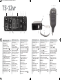 2
2
-
 3
3
-
 4
4
-
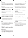 5
5
-
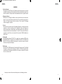 6
6
-
 7
7
-
 8
8
-
 9
9
-
 10
10
-
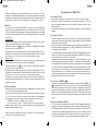 11
11
-
 12
12
-
 13
13
-
 14
14
-
 15
15
-
 16
16
-
 17
17
-
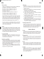 18
18
-
 19
19
-
 20
20
-
 21
21
-
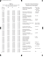 22
22
-
 23
23


itAM electronic TS-12vr Manuel utilisateur
- Taper
- Manuel utilisateur
dans d''autres langues
- italiano: itAM electronic TS-12vr Manuale utente
- English: itAM electronic TS-12vr User manual
- español: itAM electronic TS-12vr Manual de usuario
- Deutsch: itAM electronic TS-12vr Benutzerhandbuch
- Nederlands: itAM electronic TS-12vr Handleiding
Autres documents
-
Albrecht AE 6491 VOX Le manuel du propriétaire
-
Albrecht AE 6491 NRC Le manuel du propriétaire
-
Albrecht AE 6120 VOX, Mini-CB Funk Le manuel du propriétaire
-
PNI Escort HP 8000L CB Radio Manuel utilisateur
-
-
-
-
Midland ALAN 121 Le manuel du propriétaire
-
stabo xm 3004e VOX 12 Mode d'emploi
-
Albrecht AE 6110, Mini-CB Funk, Multi Le manuel du propriétaire