Josef Kihlberg F561PN Manuel utilisateur
- Taper
- Manuel utilisateur

05.20
F561PN
Pneumatic Industrial stapler
Pneumatisk Planhäftare
Pneumatische Flachhefter
Agrafeuses por côtés
From series no 1402486
Från serienummer 1402486
Ab Serie-Nr. 1402486
A partir du no de série 1402486
ENGLISH 3
SVENSKA 14
DEUTSCH 26
FRANÇAIS 38
Before using the
industrial stapler, read
the operating instruc-
tions carefully.
Läs igenom bruks-
anvisningen noga innan
du använder maskinen.
Vor dem Gebrauch der
Flachhefter die Betrieb-
sanleitung aufmerksam
lesen.
Avant l’utilisation de
l’appareil, consultez
soigneusement le
mode d’emploi.
OPERATING INSTRUCTIONS Translation of original manual
BRUKSANVISNING Original bruksanvisning
BETRIEBSANLEITUNG Übersetzung der Originalbetriebsanleitung
MODE D‘EMPLOI Traduction du mode d’emploi original

205.20
Josef Kihlberg F561PN
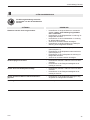
1 TECHNICAL DATA
TABLE OF CONTENTS
Weight 42 kg (92,6 lbs)
Dimensions Length 920 mm (36.2“)
Width 750 mm (29.5“)
Height 1350 mm (53.1“)
Magazine capacity 300 staples
Staple leg length 15–22 mm (5/8“ - 7/8“)
Throat depth 400 mm (15.7“)
Free anvil height 1000 mm (39.4“)
Max. air pressure 7 bar (100 psi)
Recommended
working air pressure 5 bar (72 psi)
Air consumption
per driving operation at
6 bar operating pressure 2,0 litres
A-weighted single-event
emission sound pressure
level at work station 84 dB
A-weighted sound
energy level 91 dB
FASTENERS
Staple JK561-15K (5/8“) Art.No 400145
Staple JK561-18K (3/4“) Art.No 400153
Staple JK561-22K (7/8“) Art.No 400158
Page
1 Technical data 2
2 General information 3
2.1 Information on environmental protection 3
3 Safety instructions 4
4 Description 5
4.1 Design 5
4.2 Function 5
5 Initial operation 6
5.1 Installation 6
5.2 Compressed air connection 6
6 Operating instructions 7
6.1 Loading the industrial stapler 7
6.2 Operating the industrial stapler 8
6.3 Control the clinch 9
7 Preventive and corrective maintenance 10
7.1 Lubrication 10
7.2 Cleaning the industrial stapler 10
7.3 Removing jammed staples 10
7.4 Adjustment stapling head bearing 11
7.5 Adjustment staple clinch 11
7.6 Replace stapling head 12
7.7 Replace feed spring or pusher 12
7.8 Replace driver blade or return springs 12
8 Trouble shooting 12
9 Parts list with recommended wear parts 50
Exploded drawing 51
10 Parts list - Head HH561/12-22 52
Exploded drawing 53
SE JOSEF KIHLBERG AB
Industrigatan 37B
SE-544 50 HJO
Telephone: +46 503 328 00
Fax: +46 503 328 01
Internet: www.kihlberg.com
DECLARATION OF CONFORMITY
We take sole responsibility for declaring that the
bottom stapler F561PN, to which this declaration
refers, is in full compliance with the current require-
ments of the guidelines laid down by the council
on 17th May 2006 (2006/42/EG) “Machine
Guidelines“.
Complies with norms: ISO 12100:2010
SE-544 50 HJO, 04.05.2020
Plant Manager:
Thor-Björn Elmers
Agent for the publication of technical documentation:
Josef Kihlberg AB, Industrigatan 37B SE-544 50 HJO

05.20 3
Josef Kihlberg F561PN
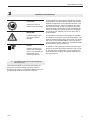
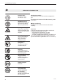
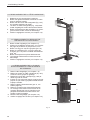
CAUTION!
Used where there is
danger to life and health.
WARNING!
Used for danger which
can cause material
damage.
NOTE!
Used for general infor-
mation and information
which if not followed can
cause faults in the
operating sequence.
2 GENERAL INFORMATION
These operating instructions are intended to simplify
familiarisation with the industrial stapler and the pos-
sibilities of application for the intended purpose. The
operating instructions contain important information
concerning the safe, proper and efcient use of the
industrial stapler. Observation of the information will
help to avoid danger, reduce repairs and stoppages
and increase the reliability and service life of the in-
dustrial stapler.
The operating instructions must always be available
at the place of operation of the industrial stapler. They
must be read and observed by all persons concerned
with work on the industrial stapler. This work speci-
cally includes operation, relling of operating material,
fault elimination and maintenance.
In addition to the operating instructions and the regu-
lations for accident prevention effective in the country
of use and place of application, the recognised tech-
nical regulations for safety and proper working must
also be observed.
2.1 INFORMATION ON ENVIRONMENTAL
PROTECTION
This industrial stapler is manufactured without any
physical or chemical substances which could be
dangerous to health. For disposal of all the parts, the
governmental instructions must be observed.

405.20
Josef Kihlberg F561PN
Use for the intended purpose
The industrial stapler is intended for stapling corruga-
ted cardboard.
This industrial stapler was designed and manufac-
tured for safe handling during the stapling operation.
Possible misuse
The industrial stapler is designed to be used only with
corrugated cardboard.
Servicing
The following maintenance work must be carried out
at regular intervals, varying with working conditions
and workload:
– daily check of compressed air pressure (4–6 bar).
– clean the industrial stapler regularly.
– check the condition of the industrial stapler at regu-
lar intervals for defects or worn parts. Never use a
industrial stapler that has defective or worn parts
(for sevice work refer also to chapters 7.1 and
7.2).
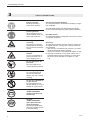
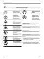
3 SAFETY INSTRUCTIONS
Inform yourself!
Read the operating
instructions carefully.
Protect yourself!
When operating the in-
dustrial stapler, wear eye,
and/or ear protection.
Warning: Danger of
crushing!
Do not put your ngers
underneath the protector.
Do not remove protection
covers.
Warning:
Hazard!
Lay the compressed air
hose so that there is no
risk of tripping over it.
Do not exceed the air
pressure!
Do not exceed the re-
commended air pressure.
Use safety coupling!
For connecting the air
hose to the industrial
stapler, use only a safety
coupling.
Do not use a bottled air
or gas source!
Do not operate this in-
dustrial stapler by using a
bottled air or gas source.
Original
JOSEF KIHLBERG
staples must be used
exclusively.
Original
JOSEF KIHLBERG
spare parts must be
used exclusively!
Not using original spare
parts will void the warran-
ty and the liability.
PD[
EDU
0
2
4
6810
12
14
16
.,+/%(5*
2ULJLQDO
KIHLBERG
Original

05.20 5
Josef Kihlberg F561PN
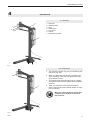
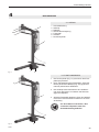
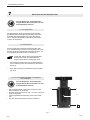
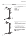
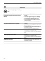
4 DESCRIPTION
4.2 FUNCTION
1. The pressure cylinder (Fig. 2/1) is activated by the
foot valve (Fig. 2/2).
2. When you press the foot valve the cylinder pres-
ses the stapling head (Fig.2/3) against the manu-
ally positioned carton.
3. The stapling head automatically pushes a staple
through the carton and the staple clinches against
the anvil.
4. When you release the foot valve the stapling
head is returned and the industrial stapler is ready
for next stapling.
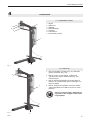
4.1 DESIGN
1 Protector
2 Stapling head
3 Anvil
4 Safety latch
5 Foot valve
6 Pusher
7 Pneumatic cylinder
Fig. 1
Fig. 2
Warning: before stapling, ensure that
no part of your body is underneath
the protector.
23
1
5
4
7
6
3
2
1

605.20
Josef Kihlberg F561PN
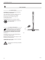
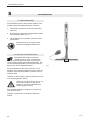
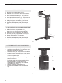
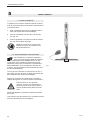
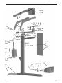
5 INITIAL OPERATION
Fig. 3
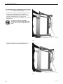
5.1 INSTALLATION
The industrial stapler is delivered with the rear foot
dis-
assambled. Assemble as following:
1. Remove the industrial stapler and the rear foot
from the carton.
2. Assemble the rear foot according to Fig. 3.
Tighten the two screws, (Fig. 3/1).
3. Place the industrial stapler on level, rm and
cleanworking ground.
Lay the compressed air hose so that
there is no risk of tripping over it.
5.2 COMPRESSED AIR CONNECTION
Properly prepared compressed air is essen-
tial for troublefree operation of the industrial
stapler. This can only be ensured by a reliably functio-
ning maintenance unit, consisting of water separator,
pressure reducing valve with pressure gauge.
The internal diameter of the pipe should be at least
10 mm (3/8“).
The industrial stapler doesn´t need any lubrication.
Connect and adjust the air pressure to the lowest
possible, approx. 5,0 bars (72 psi), which clinch the
staples correctly.
Never exceed the maximum permitted air
pressure of 8 bar (110 psi). The maximum
supply pressure is 8 Bar (110 psi).
Low air pressure will give low mainte-
nance costs!
1

05.20 7
Josef Kihlberg F561PN
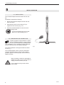
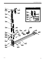
6 OPERATING INSTUCTIONS
Fig. 5
Fig. 6
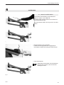
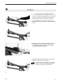
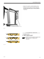
6.1 LOADING THE INDUSTRIAL STAPLER
– Always use Josef Kihlberg original staples
JK561-15, JK561-18 or JK561-22.
The correct type of staple is marked on the left side
of the magazine.
– Pull the pusher back and lift up the pusher into its
rear holder.
– Insert staple strips from the rear.
– Do not overload the magazine.
– Release the pusher.
Do not release the pusher directly from
the rear when the magazine is empty,
carefully guide it forward.
Fig. 4

805.20
Josef Kihlberg F561PN
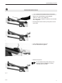
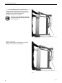
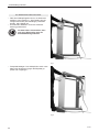
6.2 OPERATING THE INDUSTRIAL STAPLER
– Load the stapling head with staples, (refer to chap-
ter 6.1). Ensure to use the right length of the staple
(refer to chapter 6.3).
– Place the carton underneath the protector.
– Activate the foot valve.
– The stapling head presses the carton and
automatically clinches the staple against the anvil.
Fig. 7
Fig. 8
Warning: before stapling, ensure that
no part of your body is underneath
the protector.

05.20 9
Josef Kihlberg F561PN
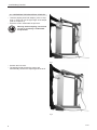
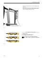
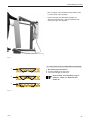
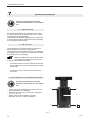
6.3 CONTROL THE CLINCH
1 Good clinch.
2 Leg length of the staple too long.
3 Leg length of staple too short.
Always use Josef Kihlberg original
staples: JK561-15, JK561-18 or JK561-22.
Fig. 9
– When you release the foot valve the stapling head
will return.
– Move the carton to the next staple position and ac-
tivate the foot valve again. Repeat until the correct
amount of staples have been used.
Fig. 10
To short
Correct
To long staple
Fel
To short
Correct
To long staple
Fel
To short
Correct
To long staple
Fel
3
2
1

10 05.20
Josef Kihlberg F561PN
7 PREVENTIVE AND CORRECTIVE MAINTENANCE
7.1 LUBRICATION
The linkage bearings are greased at delivery.
At regular intervals (monthly) lubricate them with oil.
Also lubricate the moving parts in the stapling head
with a few drops of oil.
7.2 CLEANING THE INDUSTRIAL STAPLER
This industrial stapler does not require special servi-
cing. It only needs regular cleaning with a non-aggres-
sive (non-corrosive) cleaning agent. Do not remove
any parts for cleaning purposes!
Check the proper functioning of all safety
devices daily. Make especially sure that:
– the foot valve safety latch and the protector move
freely without binding or sticking.
– all screws and nuts are securely tightened.
Before carrying out any maintenance
tasks on the industrial stapler always
rst disconnect it from the air supply.
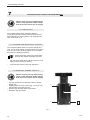
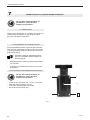
– Pull the pusher back to take the pressure off the
staple strip.
– Slightly loosen the ve screws (Fig. 11/1 and 11/2)
that hold the front plate one turn.
– Remove the jammed staple downwards.
– Retighten the ve screws.
7.3 REMOVING JAMMED STAPLES
Before carrying out any maintenance
tasks on the industrial stapler always
rst disconnect it from the air supply.
Fig. 11
2
1
11
1
1

05.20 11
Josef Kihlberg F561PN
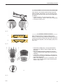
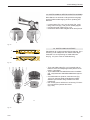
7.5 ADJUST STAPLE CLINCH
Each industrial stapler is tested carefully before
delivery. Following rough treatment during transport a
screw may become loosened and the anvil may there-
fore have to be adjusted. Incorrect stapling may occur
(Fig. 13/1).
– Press down a staple (Fig. 14/1) by hand until the
staple legs are visible or insert a single staple into
the canal.
– Move the staple head down towards the anvil (Fig.
14/2) and check that the staple legs hit the anvil sym-
metrically.
– If necessary, loosen the screw (Fig. 14/3) and cen-
tre the anvil to the staple. Remember to tighten the
screw after adjustment.
– Make a test stapling in a piece of cardboard. If the
anvil is correctly adjusted, the clinch should be as
shown in (Fig. 13/2).
7.4 ADJUSTMENT OF STAPLING HEAD BEARING
Upon delivery, the stapling head bearing is tight but
easily movable. After being in use for a while, the be-
aring will have become worn and must be readjusted
as follows:
– Loosen nut (Fig. 12/1) and screw (Fig. 12/2).
– Tighten screw (Fig. 12/2) to obtain just enough play.
– Lock with nut (Fig. 12/1).
Fig. 13
To short
Correct
To long staple
Fel
2
To short
Correct
To long staple
Fel
1
Fig. 14
1
2
Fig. 12
1 2
3

12 05.20
Josef Kihlberg F561PN
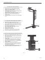
7.7 REPLACE FEED SPRING OR PUSHER
1. Remove the stapling head as per (7.6).
2. Remove the tension pin (pos. 22, exploded draw-
ing on page 53) with a punch with size 4,9 mm.
3. Dismantle the o-ring (pos.26) holding the lockpin
(pos. 24) and remove the pin.
4. Remove the pusher (pos. 12), feed spring
(pos. 18) and rollers (pos. 25).
5. Replace defective parts.
6. Assemble in reverse order.
7. Assemble the stapling head to the machine.
8. Adjust the stapling head as described (7.5)
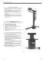
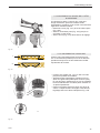
7.6 REPLACE STAPLING HEAD
1. Ensure that the air supply is disconnected.
2. Remove the remaining staples and place the
pusher in its forward position.
3. Disassemble the two hexscrews holding the links
to the stapling head. (Fig. 15/1)
4. Disassemble the two cylinder screws holding the
stapling head to its bearing. (Fig. 15/2)
5. Replace the stapling head and assemble in
reverse order.
6. Adjust the stapling head to the anvil as described
(7.5).
Fig. 15
7.8 REPLACE DRIVER BLADE / RETURN SPRINGS
1. Remove the stapling head as per chapter (7.6).
2. Dismantle the four screws (Fig. 16/1) and remove
the unit from the rail.
3. Dismantle the screw (Fig. 16/2) and remove the
spring guide.
4. Insert a large screwdriver into the channel and
turn until the pins get lose from the front plate.
5. Remove the driver blade (pos. 6, exploded draw-
ing on page 53).
6. Replace defective parts and replace it.
7. Assemble in reverse order. Please note that the
bevel at the driver blade must be turned to the
rear against the staples rail
8. Assemble the stapling head to the machine (7.6).
9. Adjust the stapling head as described (7.5)
1
2
Fig. 16
2
1
11
1
1

05.20 13
Josef Kihlberg F561PN
8 TROUBLE SHOOTING
FAULT
Staples are not fed properly
Staples are deformed when inserted
Noise level is too high
The carton is damaged by the stapling head
The carton is not pressed together properly
Removing a staple which has got stuck
ELIMINATION
– Check if the right type of staples is used.
Always use Josef Kihlberg original staples.
– Check if the feeder spring is not defective. If
necessary replace.
– Check if the staple pusher is not defective. If
necessary replace.
– Clean the staple track.
– Check return spring in the stapling head. If
necessary replace.
– Check if stapling head bearing has no play (refer
to chapter 7.4).
– Check if anvil is properly centered. (refer to chap-
ter 7.5).
Check if driver is not damaged. If necessary
replace.
– Check if the staple channel is clean.
– Check if the air pressure is correct, (5 bar/70 psi).
– Check if the stroke speed is not unnecessarly
high.
– Check if the air pressure is correct, (5 bar/70 psi).
– Check if the stroke speed is not unnecessarly
high.
– Check if the length of piston rod is adjusted pro-
perly. If necessary adjust.
– Refer to chapter 7.3.
Before carrying out trouble shooting
on the industrial stapler always rst
disconnect it from the air supply.

14 05.20
Josef Kihlberg F561PN
1 TEKNISK DATA
INNEHÅLL
Vikt 42 kg (92,6 lbs)
Mått Längd 920 mm (36.2“)
Bredd 750 mm (29.5“)
Höjd 1350 mm (53.1“)
Magasinskapacitet 300 klammer
Klammerlängd 15 - 22 mm (5/8“ - 7/8“)
Häftdjup 400 mm (15.7“)
Fri städhöjd 1000 mm (39.4“)
Max lufttryck 7 bar (100 psi)
Rekommenderat
arbetstryck 5 bar (72 psi)
Luftförbrukning per slag
vid 6 bar arbetstryck 2,0 liter
Deklarerad A-vägd
ljudtrycksnivå vid
operatörsplatsen för
enstaka förlopp 84 dB
Deklarerad A-vägd
ljudenerginivå 91 dB
KLAMMER
Klammer JK561-15K (5/8“) Art.Nr 400145
Klammer JK561-18K (3/4“) Art.Nr 400153
Klammer JK561-22K (7/8“) Art.Nr 400158
Page
1 Tekniska data 14
2 Allmänt 15
2.1 Miljöinformation 15
3 Säkerhetsföreskrifter 16
4 Beskrivning 17
4.1 Sammansättning 17
4.2 Funktion 17
5 Idrifttagande 18
5.1 Installation 18
5.2 Anslut tryckluft 18
6 Användning 19
6.1 Ladda planhäftaren 20
6.2 Användning av planhäftaren 20
6.3 Kontrollera klammerns bockning 21
7 Förebyggande och avhjälpande underhåll 22
7.1 Smörjning 22
7.2 Rengöring av planhäftaren 22
7.3 Avlägsna en klammer som fastnat 23
7.4 Inställning av häfthuvudets lagring 23
7.5 Inställning av städ
7.6 Byte av häfthuvud 24
7.7 Byte av frammatarfjäder eller frammatare 24
7.8 Byte av drivare eller returfjäder 24
8 Felsökning 25
9 Reservdelslista 50
Sprängskiss 51
10 Reservdelslista - häfthuvud 52
Sprängskiss 53
SE JOSEF KIHLBERG AB
Industrigatan 37B
SE-544 50 HJO
Telefon: +46 503 328 00
Fax: +46 503 328 01
Hemsida: www.kihlberg.com
SVENSKA
FÖRSÄKRAN OM ÖVERENSSTÄMMELSE
Försäkrar härmed att bottenhäftaren F561PN, är
tillverkad enligt följande harmoniserande stan-
darder:
SS-EN ISO 12100:2010 samt följer rådets direktiv:
2006/42/EG
SE-544 50 HJO, 04.05.2020
Plant Manager:
Thor-Björn Elmers
Behörig att ställa samman den tekniska dokumentation
+46 503 32800:

05.20 15
Josef Kihlberg F561PN
2 ALLMÄNT
Denna manual är framtagen för att förenkla kännedo-
men om planhäftaren och dess handhavande och
applikationer. Manualen innehåller viktig information
angående säkerhet, korrekt och effektiv användning.
Genom att iakttaga denna information hjälper det till
att förhindra olyckor och reducera reparationer och
driftstörningar och förlänga livslängden på planhäftare.
Manualen skall alltid hållas tillgänglig i arbetsområdet
för planhäftaren. Den skall läsas och förstås av all
personal som använder häftaren.
Som tillägg till maualen skall bestämmelse för före-
byggande olycksfallsrisker följas för det land där
produkten används. Det skall också iakttagas tekniska
förordningar angående säker och riktig användning.
-------------------
FÖRBUD!
Symbolen används vid
fara för liv och lem.
VARNING!
Symbolen används vid
risk för materiella skador.
OBSERVERA
Symbolen används för
allmänna instruktioner
samt för instruktioner
som måste följas för att
undvika störningar
i driften.
2.1 MILJÖINFORMATION
Denna planhäftare är tillverkad utan några fysisk eller
kemiska substanser vilka kan vara farliga för hälsan.
För avfallshantering av samtliga delar skall regerin-
gens lagar och förordningar följas.

16 05.20
Josef Kihlberg F561PN
Användningsområde
Planhäftaren är avsedd för att häfta wellpappkarton-
ger.
Planhäftaren är konstruerad för säker hantering under
klamringen.
Möjlig felanvänding
Planhäftaren är konstruerad för att enbart häfta i
wellpapp.
Underhåll
Följande underhåll måste genomföras regelbundet
beroende på arbetsmiljö och volym:
– daglig kontroll av arbetstryck. (4–6 bar).
– regelbunden rengöring av planhäftaren.
– kontrollera regelbundet konditionen på häftaren och
se till att inga defekta eller utslitna delar förekommer.
(för mer information angående service se 7.1 and 7.2).
3 SÄKERHETSFÖRESKRIFTER
Informera dig!
Läs igenom bruks-
anvisningen noga.
Skyddsutrustning!
Bär skyddsutrustning för
ögon och öron när du
använder planhäftaren.
Varning: Akta ngrarna!
Stoppa inte ngrar eller
andra kroppsdelar under
skyddet. Plocka inte bort
skyddet.
Varning: Snubbelrisk!
Lägg tryckluftsslangen
så att det inte nns
någon risk för att
snubbla över den.
Överskrid inte
lufttrycket!
Överskrid inte rekom-
menderat lufttryck.
Använd säkerhets-
koppling!
Anslut luftslangen till
planhäftaren endast med
säkerhetskoppling.
Använd aldrig gas från
högtryckstuber!
Använd aldrig plan-
häftaren med gas från
högtryckstuber.
Använd alltid Josef
Kihlberg original
klammer.
Endast original-
reservdelar från
JOSEF KIHLBERG
får användas!
I annat fall upphävs
garanti och övrigt ansvar
från tillverkaren!
PD[
EDU
0
2
4
6810
12
14
16
.,+/%(5*
2ULJLQDO
KIHLBERG
Original

05.20 17
Josef Kihlberg F561PN
4 BESKRIVNING
4.2 FUNKTION
1. Den pneumatiska cylindern (Fig. 2/1) aktiveras
genom fotventilen (Fig. 2/2).
2. När du trycker ner fotventilen, så aktiveras
cylindern som pressar häfthuvudet (Fig. 2/3)
mot kartongen.
3. När du aktiverar fotpedalen förs automatiskt en
klammer ut ur häfthuvudet genom kartongen och
böjs mot städet.
4. När du avaktiverar fotpedalen returnerar häfthu-
vudet automatiskt och häftaren är klar för nästa
klammer.
4.1 SAMMANSÄTTNING
1 Skydd
2 Häfthuvud
3 Häftstäd
4 Säkerhetsspärr
5 Fotventil
6 Frammatare
7 Pneumatisk cylinder
Varning innan du häftar, säkerställ att
ingen del av din kropp är under berör-
ningsskyddet.
Fig. 1
Fig. 2
2
3
1
5
4
7
6
3
2
1

18 05.20
Josef Kihlberg F561PN
5 IDRIFTTAGANDE
1
Fig. 3
5.1 INSTALLATION
Planhäftaren är levererad med bakre foten demon-
terad. Monteras enligt följande:
Tag ur planhäftaren ur kartongen. Bakre foten är bi-
packad inuti stativet skyddad med wellpapp.
Montera bakre foten till stativet enligt Fig. 3.
och drag fast skruvarna.
Placera planhäftaren på ett rent plant underlag.
Placera tryckluftsslangen så att den ej
utgör något hinder.
5.2 ANSLUT TRYCKLUFT
Häftaren behöver ren och torr tryckluft för
en långsiktig problemfri drift. Detta kan
enklast upnås med en luftberedare som inkluderar
vattenavskiljare och luftregulator med manometer.
Tryckluftsslangens innerdiameter bör vara minst
10 mm (3/8“).
Planhäftaren behöver inte någon tillsatssmörjning.
Använd lägsta möjliga lufttryck.
Börja med 5.0 bar (72 psi) och öka i steg om 0.5 bar
tills klammern böjs på rätt sätt.
Högsta tillåtna tryck är 8 bar (110 psi), och maximalt
matartryck är 8 bar (110 psi).
Lågt arbetstryck innebär låga underhålls-
kostnader.

05.20 19
Josef Kihlberg F561PN
6 ANVÄNDNING
6.1 LADDA PLANHÄFTAREN
– Använd alltid Josef Kihlberg original klammer:
JK561-15, JK561-18 or JK561-22.
På häfthuvudets vänstra sida nns en etikett som
visar aktuell klammertyp.
– Dra frammataren bakåt och lyft upp den i sin bakre
hållare.
– Klammerstavarna förs in bakifrån.
– Ladda inte så många klammer i magasinet att
frammataren skadas när slutstycket fälls ner igen.
– Frigör frammataren.
Släpp aldrig frammataren från sitt bakersta
läge vid tomt magasin, utan för fram det
försiktigt för hand.
Fig. 5
Fig. 6
Fig. 4

20 05.20
Josef Kihlberg F561PN
Fig. 7
Fig. 8
6.2 ANVÄNDNING AV PLANHÄFTAREN
– Ladda magasinet med klammer om det är tomt
(se kapitel 6.1). Kontrollera att du laddat med rätt
benlängd av klammern (se kapitel 6.3).
– Placera kartongen under skyddet.
– Aktivera fotventilen.
– Häfthuvudet pressas mot kartongen och bockar
klammern automatiskt mot häftstädet.
Varning! Innan du påbörjar häftning,
kontrollera att ingen kroppsdel nns
under skyddet.
La page est en cours de chargement...
La page est en cours de chargement...
La page est en cours de chargement...
La page est en cours de chargement...
La page est en cours de chargement...
La page est en cours de chargement...
La page est en cours de chargement...
La page est en cours de chargement...
La page est en cours de chargement...
La page est en cours de chargement...
La page est en cours de chargement...
La page est en cours de chargement...
La page est en cours de chargement...
La page est en cours de chargement...
La page est en cours de chargement...
La page est en cours de chargement...
La page est en cours de chargement...
La page est en cours de chargement...
La page est en cours de chargement...
La page est en cours de chargement...
La page est en cours de chargement...
La page est en cours de chargement...
La page est en cours de chargement...
La page est en cours de chargement...
La page est en cours de chargement...
La page est en cours de chargement...
La page est en cours de chargement...
La page est en cours de chargement...
La page est en cours de chargement...
La page est en cours de chargement...
La page est en cours de chargement...
La page est en cours de chargement...
La page est en cours de chargement...
La page est en cours de chargement...
La page est en cours de chargement...
La page est en cours de chargement...
-
 1
1
-
 2
2
-
 3
3
-
 4
4
-
 5
5
-
 6
6
-
 7
7
-
 8
8
-
 9
9
-
 10
10
-
 11
11
-
 12
12
-
 13
13
-
 14
14
-
 15
15
-
 16
16
-
 17
17
-
 18
18
-
 19
19
-
 20
20
-
 21
21
-
 22
22
-
 23
23
-
 24
24
-
 25
25
-
 26
26
-
 27
27
-
 28
28
-
 29
29
-
 30
30
-
 31
31
-
 32
32
-
 33
33
-
 34
34
-
 35
35
-
 36
36
-
 37
37
-
 38
38
-
 39
39
-
 40
40
-
 41
41
-
 42
42
-
 43
43
-
 44
44
-
 45
45
-
 46
46
-
 47
47
-
 48
48
-
 49
49
-
 50
50
-
 51
51
-
 52
52
-
 53
53
-
 54
54
-
 55
55
-
 56
56


Josef Kihlberg F561PN Manuel utilisateur
- Taper
- Manuel utilisateur
dans d''autres langues
- English: Josef Kihlberg F561PN User manual
- Deutsch: Josef Kihlberg F561PN Benutzerhandbuch
- svenska: Josef Kihlberg F561PN Användarmanual
Documents connexes
-
Josef Kihlberg B561PN Manuel utilisateur
-
-
-
-
-
-
-
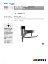 Signode JK20-680FN Manuel utilisateur
-
-
