FS M6800 Series Mode d'emploi

Taper
Mode d'emploi
ALM
SYS
14710 13 16 19 22
2 3
CONSOLE RESET LED TEST
56
8911 12 14 15 17 18 20 21 23 24
MGMT1 MGMT2
1
4
7
10
13
16
19
22
TSP16
V2.0
PLATE-FORME OTN DE SÉRIE M6800
OTN PLATFORM DER M6800-SERIE
M6800 SERIES OTN PLATFORM
Quick Start Guide
Quick-Start Anleitung
Guide de Démarrage Rapide
1
EN
Introduction
M6800-TSP16 is an OTN transmission platform customized for Data Center Interconnect (DCI)
applications. It's up to eight single wavelength 200G channels, with 8x 200G CFP2 coherent optics
uplinks on the line side, and 16x 100G QSFP28 on the client side.
ALM
SYS
2
1 4 7 10 13 16 19 22
3 5 6 8 9 11 12 14 15 17 18 20 21 23 24 CONSOLE RESET LED TEST
MGMT1 MGMT2
TSP16
1
4
7
10
13
16
19
22
M6800-TSP16
Accessories
Power Cord x2 Console Cable x1 Ethernet Cable x1
Grounding Cable x1Cable Manager x1 Mounting Bracket x2 ESD Wrist Strap x1
M4 Screw x8M6 Screw Set x4
CD x1
2
EN
Hardware Overview
ALM
SYS
2
1 4 7 10 13 16 19 22
3 5 6 8 9 11 12 14 15 17 18 20 21 23 24 CONSOLE RESET LED TEST
MGMT1 MGMT2
TSP16
1
4
7
10
13
16
19
22
Front Panel Ports
Front Panel LED
Port Description
Line Port
MGMT1~2
CONSOLE
Clinet Port
Support 8x coherent 200G CFP2
Connect to the local network management computer
Debugging & Upgrading port
Support 16x 100G QSFP28
CFP2
RJ45 ETH
Micro USB
QSFP28
Port Type
Line Port MGMT1
CONSOLEClinet Port
MGMT2
ALM
SYS
2
1 4 7 10 13 16 19 22
3 5 6 8 9 11 12 14 15 17 18 20 21 23 24 CONSOLE RESET LED TEST
MGMT1 MGMT2
TSP16
1
4
7
10
13
16
19
22
ALM
SYS
LED Status Description
ALM
SYS
Slow Flash of Red Light There is a major alarm of the device.
Quick Flash of Red Light
Always OFF
Slow Flash of Green Light
Always OFF
Always Red
There is a critica alarm of the device.
There is no alarm of the device.
There is a minor alarm of the device.
The system is not normally enabled.
The system works normally.
3
EN
Site Environment
measures must be taken.
Ensure there is no water on the storage oor and no leakage to the packing box of the equipment.
Avoid automatic re ghting facilities, heating system and other places where leakage may occur.
Keep the equipments indoors. If it is in rainy season or in humid environment, dehumidication
LED Status Description
Port Indicator Quick Flash of Red Light There is a mismatch alarm of the port.
Always OFF
Always Green
Always Red
The port is disabled.
There is no los and mismatch alarm of the port.
There is a los alarm of the port.
LED Status Description
FAN Always Red There is alarm of those fans.
Always Green There is no alarm of those fans.
Back Panels
Back Panel LED
FAN FAN FAN
3 Fans
Dual AC Power, 100~240V
FAN
FAN FAN FAN
4
EN
ALM
SYS
14710 13 16 19 22
23
CONSOLE RESET LED TEST
56
8911 12 14 1517 18 20 2123 24
MGMT1 MGMT2
1
4
7
10
13
16
19
22
TSP16
Installing
13 16 19 22
CONSOLE RESET LED TEST
14 15 17 18 20 21 23 24
MGMT1 MGMT2
7
10
13
16
19
22
Installing Mounting Brackets
1. Secure the mounting brackets to the two sides of the 200G transponder with 8x M4 screws.
1. Put the 200G transponder on the shelf in the cabinet.
2. Install and tighten the panel with 4 sets of M6 screws.
3. Cable manager can be installed together with mounting brackets to the cabinet.
ALM
SYS
TSP16
5
EN
ALM
SYS
14710 13
2 3
56
8911 12 14 15
1
4
7
10
TSP16
1. Before touching any device or module, wear an ESD wrist strap or ESD gloves to protect sensitive
components against electrostatic discharge from the human body.
2. Connect other end of the ESD wrist strap to the PGND point on the device.
1. Secure the grounding lug to the grounding point on the chassis front panel with the washers and
screws.
2. Connect the other end of the cable to a proper earth ground, such as the rack in which 200G
transponder is mounted.
Wearing ESD Wrist Strap
4710 13 16 19 22
CONSOLE RESET LED TEST
56
8911 12 14 15 17 18 20 21 23 24
MGMT1 MGMT2
1
4
7
10
13
16
19
22
Grounding the 200G Transponder
CAUTION: The earth connection must not be removed unless all supply connections have
been disconnected
6
EN
19 22
CONSOLE RESET LED TEST
20 21 23 24
MGMT1 MGMT2
13
16
19
22
Connecting Power Cord
1. Plug AC power cord into the power port on the front panel of AC power module.
2. Connect the other end of the power cord to an AC power source.
ALM
SYS
14710 13 16 19 22
2 3
CONSOLE RESET LED TEST
56
8911 12 14 15 17 18 20 21 23 24
MGMT1 MGMT2
1
4
7
10
13
16
19
22
TSP16
Connecting QSFP28 Transceiver
1. Plug the QSFP28 transceiver into the QSFP28 slot on transponder.
2. Connect one end of ber cable to the QSFP28 transceiver.
3. Connect the other end of ber cable to switch.
WARNING: Do not install power cables while the power is on.
7
EN
1. Connect one end of the standard RJ45 Ethernet cable to the MGMT1&2 port on the 200G
transponder.
2. Connect the other end of cable to a computer.
ALM
SYS
14710 13 16 19 22
2 3
CONSOLE RESET LED TEST
56
8911 12 14 15 17 18 20 21 23 24
MGMT1 MGMT2
1
4
7
10
13
16
19
22
TSP16
Connecting Coherent CFP2 Transceiver
1. Plug the CFP2 transceiver into the CFP2 slot on transponder.
2. Connect one end of ber cable to the CFP2 transceiver.
3. Connect the other end of ber cable to mux demux or optical amplier module.
Connecting to the Management Ports
19 22
CONSOLE RESET LED TEST
20 21 23 24
MGMT1 MGMT2
19
22
8
EN
Conguring the M Series Platform
Conguring the M Series Platform Using the Web-based Interface
Step 1: Connect your computer with the network cable to any Ethernet MGMT port of the NMU
Step 2: Get the NMS software from the CD of chassis accessories or deownload the le “NMS software”
module.
online, and then install it.
License Tool
Please Enter the Key:
Key:
Validate Close
NMS Server
Step 3: Double Click “NMS Server icon on the desktop and the dialogue box of license validation will
pop up.Enter the license key(included in the CD) to nish validation. (If you can’t nd the
license key,please contact FS asles manager for help.)
9
EN
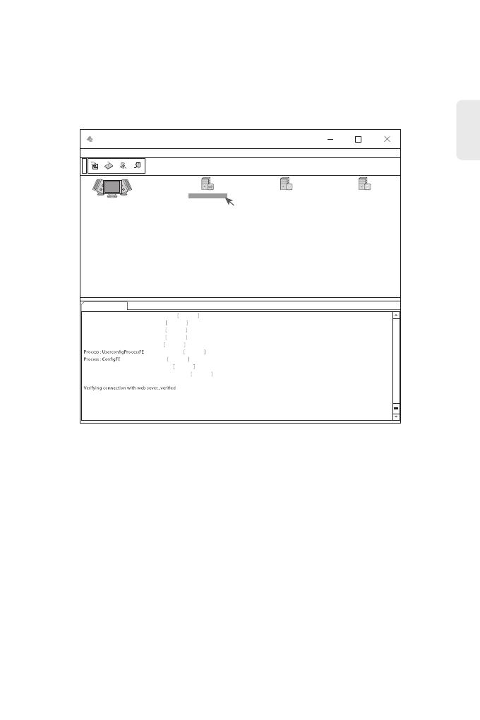
Step 4: Then the NMS server interface pops up. Double click “Start NMS Server" to run the server,
when it prompts “Please connect your client to the web server on port: 9090”, it means that
you have successfully started the NMS server. And then you can close the NMS Server window,
the server is still running in the background.
Step 5: Open a browser window. (Recommend IE11.0 and above version or Google Chrome browser).
(1) If you log in from local NMS host, enter localhost:9090 in the address bar to open the login
interface.
(2) If you log in from other remote host, enter the server IP address XXX.XXX.XXX.XXX:9090
(IP address of NMS server) to open the login interface.
NMS
Options Edit Help
Start NMS Server
Start the NMS Server
Start NMS Server Shutdown NMS Server Reiniyialize NMS
Start NMS Server
NMS modules started successfully at Oct 08,2018 02:44:50 PM
Please connect your client to the web server on port 9090
Process : NmsSAServerFE Started
Process : EventFE Started
Process : MapFE Started
Process : PolicyFE Started
Process : AlertFE Started
Started
Started
Process : NmsMainFE Started
Process : WebNMSMgmtFEProcess Started
Troubleshooting
Module LEDs Working Abnormally
Accessing the Wed-based Conguration Page Unsuccessfully
1. Check the power cable connections at the 200G transponder and the power source.
2. Make sure that all cables are used correctly and comply with the power specications.
1. Check MGMT ports LED on the 200G transponder and make sure the Ethernet cable is connected
properly.
2. Try another port on the 200G transponder and make sure the Ethernet cable is suitable and works
3. Power o the 200G transponder.After a while, power it on again.
4. Make sure the IP address of your NMS server is correctly congured.
5. If you still cannot access the conguration page, please reinitialize NMS server to its factory
normally.
defaults.
Step 6: Enter correct user name and password (For the administrator, the default login user name is
Step 7: Click login, you are now ready to congure M series platform.
“root”, and the default password is “public”), as shown in the gure below:
M Series NMS
M Series NMS
XXX.XXX.XXX.XXX:9090
User Name
Password
Login
Reset
Copyright © 2020 by FS.COM All Rights Reserved.
NOTE: Refer to the M SERIES NETWORK MANAGEMENT USER MANUAL online for further
information.
10
EN
11
EN
Online Resources
Download https://www.fs.com/download.html
Help Center https://www.fs.com/service/help_center.html
Contact Us https://www.fs.com/contact_us.html
Product Warranty
free return within 30 Days from the day you receive your goods. This excludes any custom made
FS ensures our customers that any damage or faulty items due to our workmanship, we will oer a
items or tailored solutions.
Warranty: M6800 series enjoy 2 years limited warranty against defect in materials or
workmanship. For more details about warranty, please check at :
https://www.fs.com/policies/warranty.html
Return: If you want to return item(s), information on how to return can be found at:
https://www.fs.com/policies/day_return_policy.html
2
Business Module Cannot Be Added
1. Enter through CMD.
2. Ping business module IP to check whether it can communicate.
3. Check whether normal communication can be made between business module and NMU module.
4. Change another business module.
Einführung
M6800-TSP16 ist eine OTN-Übertragungsplattform, die speziell für Data Center Interconnect (DCI)
Anwendungen. Sie bietet bis zu acht Single-Wavelength 200G-Kanäle, mit 8x 200G CFP2 kohärenten
optischen Uplinks auf der Leitungsseite und 16x 100G QSFP28 auf der Client-Seite.
ALM
SYS
2
1 4 7 10 13 16 19 22
3 5 6 8 9 11 12 14 15 17 18 20 21 23 24 CONSOLE RESET LED TEST
MGMT1 MGMT2
TSP16
1
4
7
10
13
16
19
22
M6800-TSP16
Zubehör
Stromkabel x2 Konsolenkabel x1 Ethernet-Kabel x1
Erdungskabel x1Kabelmanager x1 Montagehalterung x2 ESD-Handschlaufe x1
M4-Schraube x8M6-Schraubensatz x4
CD x1
DE
12
DE
13
Hardware-Übersicht
ALM
SYS
2
1 4 7 10 13 16 19 22
3 5 6 8 9 11 12 14 15 17 18 20 21 23 24 CONSOLE RESET LED TEST
MGMT1 MGMT2
TSP16
1
4
7
10
13
16
19
22
Ports an der Vorderseite
LEDs an der Vorderseite
Port Beschreibung
Line Port
MGMT1~2
CONSOLE
Clinet Port
Unterstützt 8x kohärente 200G CFP2
Verbindung mit dem lokalen Netzwerk-Management-Computer
Debugging- & Upgrading-Port
Unterstützt 16x 100G QSFP28
CFP2
RJ45 ETH
Micro USB
QSFP28
Port Typ
Line Port MGMT1
CONSOLEClinet Port
MGMT2
ALM
SYS
2
1 4 7 10 13 16 19 22
3 5 6 8 9 11 12 14 15 17 18 20 21 23 24 CONSOLE RESET LED TEST
MGMT1 MGMT2
TSP16
1
4
7
10
13
16
19
22
ALM
SYS
LED Status Beschreibung
ALM
SYS
Langsames rotes Blinken Es liegt ein wichtiger Alarm des Geräts vor.
Schnelles rotes Blinken
Immer AN
Langsames grünes Blinken
Immer AUS
Rot immer AN
Es liegt ein kritischer Alarm des Geräts vor.
Es liegt kein Alarm des Geräts vor.
Es liegt ein geringer Alarm des Geräts vor.
Das System wurde nicht gestartet.
Das System wurde erfolgreich gestartet.
Einsatzort
Vergewissern Sie sich, dass kein Wasser auf der Lageräche steht und kein Wasser in den
Verpackungskarton des Geräts eindringt.
Vermeiden Sie automatische Heizungsanlagen, Heizungssysteme und andere Orte, an denen
Wasserlecks auftreten können.
Lagern und Stellen Sie die Geräte nur in Innenräumen auf. Während der Regenzeit oder in feuchter
Umgebung müssen Maßnahmen zur Entfeuchtung getroen werden.
LED Status Beschreibung
Port-Anzeige Schnelles rotes Blinken Es liegt ein Mismatch-Alarm des Ports vor.
Immer AUS
Grün immer AN
Rot immer AN
Der Port ist deaktiviert.
Es gibt keinen Los- und Mismatch-Alarm des Ports.
Es liegt ein Los-Alarm des Ports vor.
LED Status Beschreibung
FAN Rot immer AN Es gibt einen Alarm für diese Lüfter.
Grün immer AN Es gibt keinen Alarm für diese Lüfter.
Back Panels
LEDs an der Rückseite
FAN FAN FAN
3 Fans
Dual AC Power, 100~240V
FAN
FAN FAN FAN
DE
14
DE
15
ALM
SYS
14710 13 16 19 22
23
CONSOLE RESET LED TEST
56
8911 12 14 1517 18 20 2123 24
MGMT1 MGMT2
1
4
7
10
13
16
19
22
TSP16
Installation
13 16 19 22
CONSOLE RESET LED TEST
14 15 17 18 20 21 23 24
MGMT1 MGMT2
7
10
13
16
19
22
Installation der Montagehalterungen
1. Befestigen Sie die Montagehalterungen mit 8x M4-Schrauben an den beiden Seiten des
200G-Transponders
1. Stellen Sie den 200G-Transponder auf den Regalboden im Gehäuse.
2. Installieren Sie das Panel und ziehen Sie es mit 4 Sätzen M6-Schrauben fest.
3. Der Kabelmanager kann zusammen mit den Montagewinkeln am Schrank installiert werden.
ALM
SYS
TSP16
DE
16
ALM
SYS
14710 13
2 3
56
8911 12 14 15
1
4
7
10
TSP16
1. Tragen Sie vor dem Berühren der Geräte oder Module ein ESD-Armband oder ESD-Handschuhe,
um empndliche Bauteile vor elektrostatischer Entladung durch den menschlichen Körper zu
schützen.
2. Verbinden Sie das andere Ende des ESD-Armbandes mit dem PGND-Punkt am Gehäuse.
1. Befestigen Sie die Erdungslasche mit den Unterlegscheiben und Schrauben am Erdungspunkt an
der Chassis-Frontplatte.
2. Schließen Sie das andere Ende des Kabels an eine geeignete Erdung an, z. B. an das Rack, in dem
der 200G-Transponder montiert ist.
ESD-Armband
4710 13 16 19 22
CONSOLE RESET LED TEST
56
8911 12 14 15 17 18 20 21 23 24
MGMT1 MGMT2
1
4
7
10
13
16
19
22
Erdung des 200G-Transponders
VORSICHT: Der Erdungsanschluss darf erst dann entfernt werden, wenn alle
Versorgungsanschlüsse abgeklemmt wurden.
19 22
CONSOLE RESET LED TEST
20 21 23 24
MGMT1 MGMT2
13
16
19
22
DE
17
Anschließen des Netzkabels
1. Stecken Sie das AC-Netzkabel in den Netzanschluss an der Vorderseite des AC-Leistungsmoduls.
2. Schließen Sie das andere Ende des Netzkabels an eine AC-Stromquelle an.
ALM
SYS
14710 13 16 19 22
2 3
CONSOLE RESET LED TEST
56
8911 12 14 15 17 18 20 21 23 24
MGMT1 MGMT2
1
4
7
10
13
16
19
22
TSP16
Anschluss eines QSFP28-Transceivers
1. Stecken Sie den QSFP28-Transceiver in den QSFP28-Steckplatz am Transponder.
2. Schließen Sie ein Ende des Kabels an den QSFP28-Transceiver an.
3. Verbinden Sie das andere Ende des Kabels mit dem Switch.
WARNUNG: Verlegen Sie die Stromkabel nicht, während der Strom eingeschaltet ist.
ALM
SYS
14710 13
23
56
8911 12 14 15
1
4
7
10
TSP16
DE
18
1. Schließen Sie ein Ende des Standard-RJ45-Ethernet-Kabels an den MGMT1&2-Port an der
Vorderseite des 200G-Transponders an.
2. Schließen Sie das andere Ende des Kabels an einen Computer an.
ALM
SYS
14710 13 16 19 22
2 3
CONSOLE RESET LED TEST
56
8911 12 14 15 17 18 20 21 23 24
MGMT1 MGMT2
1
4
7
10
13
16
19
22
TSP16
Anschließen eines kohärenten CFP2-Transceivers
1. Stecken Sie den CFP2-Transceiver in den CFP2-Steckplatz am Transponder.
2. Schließen Sie ein Ende des Kabels an den CFP2-Transceiver an.
3. Verbinden Sie das andere Ende des Kabels mit dem Mux-Demux oder dem optischen
Verstärkermodul.
Verbindung mit den Management-Ports
16 19 22
CONSOLE RESET LED TEST
18 20 21 23 24
MGMT1 MGMT2
13
16
19
22
DE
19
Kongurieren der Plattform der M-Serie
Kongurieren der Plattform der M-Serie über die webbasierte
Benutzeroberäche
Schritt 1: Verbinden Sie Ihren Computer mit dem Netzwerkkabel mit einem beliebigen
Ethernet-MGMT-Anschluss des NMU-Moduls.
Schritt 2: Rufen Sie die NMS-Software von der CD ab oder laden Sie die Datei "NMS-Software" online
herunter, und installieren Sie sie.
License Tool
Please Enter the Key:
Key:
Validate Close
NMS Server
Schritt 3: Doppelklicken Sie auf das Symbol "NMS Server" auf dem Desktop und das Dialogfeld für die
Lizenzvalidierung wird angezeigt. Geben Sie den Lizenzschlüssel (auf der CD enthalten) ein,
um die Validierung abzuschließen. (Wenn Sie den Lizenzschlüssel nicht nden können,
wenden Sie sich bitte an den FS-Verkaufsleiter, um Hilfe zu erhalten).
  • Page 1 1
  • Page 2 2
  • Page 3 3
  • Page 4 4
  • Page 5 5
  • Page 6 6
  • Page 7 7
  • Page 8 8
  • Page 9 9
  • Page 10 10
  • Page 11 11
  • Page 12 12
  • Page 13 13
  • Page 14 14
  • Page 15 15
  • Page 16 16
  • Page 17 17
  • Page 18 18
  • Page 19 19
  • Page 20 20
  • Page 21 21
  • Page 22 22
  • Page 23 23
  • Page 24 24
  • Page 25 25
  • Page 26 26
  • Page 27 27
  • Page 28 28
  • Page 29 29
  • Page 30 30
  • Page 31 31
  • Page 32 32
  • Page 33 33
  • Page 34 34
  • Page 35 35
  • Page 36 36

FS M6800 Series Mode d'emploi

Taper
Mode d'emploi

dans d''autres langues