3com CoreBuilder 9000 ATM Interface Module Guide de démarrage rapide
- Taper
- Guide de démarrage rapide

ATM I
NTERFACE
M
ODULE
Q
UICK
S
TART
G
UIDE
This guide explains how to install a CoreBuilder™ 9000 ATM Interface
Module into a CoreBuilder 9000 chassis, how to power on the system,
how to download the sytem software and how to perform an initial
configuration.
ATM Interface
Module Description
The ATM Interface Module interfaces with the ATM Switch Fabric Module
to create the Enterprise ATM Switch system. The ATM Interface Module
can be ordered in several configurations, according to your specific
needs.
A typical Interface Module configuration comprises:
An ATM Interface Carrier Module that is an unpopulated dual-subslot
dual-channel carrier module
One or two OC-3/STM-1 four-port ATM Interface daughter card(s) that
can be either single-mode or multi-mode. The OC-3/STM-1 card is also
available in 3port multi-mode one port single-mode.
One or two OC-12/STM-4 one-port ATM Interface daughter card(s)
that can be either single-mode or multi-mode
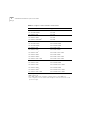
These different combinations can be ordered as pre-packaged bundles, or
the components can be ordered separately. The combination/bundle and
their corresponding part numbers are presented in appendix of the ATM
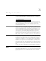
Interface Module User Guide. Table 1 shows the combinations that are
available without the part numbers.
For the CoreBuilder
™
9000 Enterprise ATM Switch

2
ATM I
NTERFACE
M
ODULE
Q
UICK
S
TART
G
UIDE
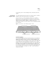
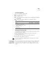
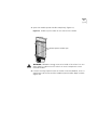
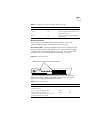
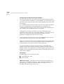
Figure 1 shows the faceplate of the ATM Interface Carrier Module with
one OC-12/STM-4 daughter card installed on the left and one
OC-3/STM-1 daughter card installed on the right.
In the figure, the Module is shown on its side; when installed, it stands
vertically in the CoreBuilder 9000 chassis with the LEDs on top.
Figure 1
ATM Interface Module Faceplate
The LED indicators on the left side of the faceplate show the module’s
operational status. The Module Status LED indicator is a general purpose
LED which shows the ATM Interface Module’s status; the two groups of
four port LEDs show the status of individual ports in the daughter cards.
Audience Description
This guide is intended for the system administrator, network equipment
technician, or network manager who is responsible for installing and
managing interface modules designed for operation with network
hardware such as CoreBuilder 9000 ATM switches. It assumes a working
knowledge of network operations and familiarity with communications
protocols used in networks.
This guide is intended for trained technical personnel only. Do not
attempt to remove or replace a CoreBuilder 9000 ATM Interface Module
if you have not had the proper training from 3Com. For training
information, call 1-800-NET-3COM.
Safety Precautions
When you handle components in a CoreBuilder 9000 system, be sure
that you follow all safety precautions. To avoid electric shocks, burns, or
equipment damage, read and follow these warnings:
WARNING: Hazardous energy exists within the CoreBuilder system. Use
extreme caution when you install, remove or replace the ATM Switch
Fabric Module.
WARNING: Allow only trained service personnel to install, remove or
replace a module.
R
x
1
T
x
R
x
2
T
x
R
x
1
T
x
R
x
2
T
x
1
1
2
3
4
1
2
2
3
4
M
o
d
.
S
t
a
t
.
R
x
4
T
x
OC-12/STM-4 Daughter Card
OC-3/STM-1 Dau
g
hter Card
Module Status LED
Port LEDs

3
WARNING: Before you open the chassis, always unplug the power cord.
WARNING: When the system is on, never insert metal objects such as a
screwdriver or a finger with jewelry into open module slots.
WARNING: When the system is on, do not touch any connections within
the chassis with your hands or fingers. Do not insert metal objects into
the backplane.
ESD Safety Information
Electrostatic Discharge (ESD) can damage components on the module.
ESD, which occurs when the module is improperly handled, can cause
complete or intermittent failures.
CAUTION: To prevent ESD-related damage:
Always wear an ESD wrist strap, ensuring that the strap is firmly
secured to your wrist.
Keep the ATM Interface Module in its antistatic shielded bag until you
are ready to install it.
When working with any component of the CoreBuilder 9000 system,
always place the card/module onto the antistatic bag that it was
shipped in. Do not work on a module or card that is not properly
grounded.
Handling Precautions
When you handle the ATM Interface Module, follow these precautions:
Always handle the Module by the faceplate only.
Do not touch the components, pins, leads, or solder connections.
When you insert the Module into the board guides, do not twist or
otherwise force the module into the chassis.
Before you push the board Module into the chassis, make sure that
the module ejectors are open.
When you slide the Module into place, match the upper and lower
module guides.
Do not operate the unit in a location where the maximum ambient
temperature exceeds 40°C (104°F).
Ensure that the chassis ventilation openings in the unit are not
blocked.

4
ATM I
NTERFACE
M
ODULE
Q
UICK
S
TART
G
UIDE
Précautions de
sécurité
Lorsque vous manipulez les éléments du système CoreBuilder 9000,
veillez à bien respecter les précautions de sécurité. Pour éviter les
décharges électriques, les brûlures, l’incendie ainsi que pour ne pas
endommager l’équipement, veuillez lire et respecter les précautions
suivantes:
AVERTISSEMENT: Le système CoreBuilder 9000 contient une énergie qui
peut être dangereuse. Soyez trez minutieux lorsque vous installez, ôtez
ou replacez un Module Interface ATM.
AVERTISSEMENT: Seul un personnel habilité à le faire peut installer, ôter
ou remplacer un Module Interface ATM.
AVERTISSEMENT: Lorsque le système CoreBuilder 9000 est sous tension,
ne jamais insérer des objets tels que tournevis ni même des doigts portant
des bijoux dans les emplacements d’un module ouvert. Lorsque le
système est sous tension, ne touchez aucune connexion du châssis avec
les mains ou les doigts. Ne pas insérer d’objets métalliques dans la face
arrière.
AVERTISSEMENT: Ne pas brancher, allumer ou essayer de faire
fonctionner un module d’évidence défectueux.
AVERTISSEMENT: Pour vous protéger les yeux lors de l’installation du
Module d’Interface ATM, respectez les précautions suivantes:
Bien que les LEDs et lasers des communications de données utilisés dans
ce produit soient conformes aux normes d’exposition oculairs éventuelle,
3Com vous recommande, comme pour toute lumière vive, de ne pas
regarder directement la source de lumière.
Information sur la prévention de décharges électrostatiques
Les décharges électrostatiques peuvent endommager des éléments du
module. Ces décharges, qui surviennent lors d’une manipulation
inadéquate du module, peuvent entraîner une défaillance temporaire ou
permanente.
ATTENTION: Pour éviter des dommages électrostatiques:
Assurez-vous d’être bien branché à la terre. Utilisez un sous-pied et un
tapis relié à la terre ou portez un bracelet mis à la terre et veillez à ce
que le contact dermique soit bon.
Conservez le module dans un sac antistatique jusqu’à son installation.

5
Précautions de manipulation
Respectez les précautions suivantes lorsque vous manipulez le Module
Interface ATM:
Tenez le module par son panneau avant uniquement.
Ne pas toucher les éléments, broches, branchements ou soudures.
Avant d’insérer le module dans le châssis, assurez-vous que les
poignées d’insertion/d’éjection sont ouvertes.
Lorsque vous faites glisser le module dans le châssis, faites coïncider
les rails inférieurs et supérieurs.
Ne jamais forcer lorsque vous insérez le module dans les rails.
Sicherheitsvorkehru-
gen
Halten Sie beim Umgang mit Modulen des CoreBuilder-9000-Systems
unbedingt alle Sicherheitsvorkenhrungen ein. Lesen und befoldgen Sie
folgende Warnungen, um elektrische Schläge, Verbrennungen, Brände
oder Materialschäden zu vermeiden:
Im CoreBuilder-System existieren hohe elektrische Spannungen. Sie
sollten deshalb das ATM-Schnittstellen-Modul nur mit aüßerster Vorsicht
installieren, entfernen oder tauschen.
Das ATM-Schnittstellen-Modul darf nur von ausgebildetem
Service-Personal installiert, entfernt oder getauscht werden.
Führen Sie bei eingeschaltetem CoreBuilder-9000-System niemals
Metallgegenstände wie Schraubenzieher oder Schmuck an Fingern in
offene Modulschlitze ein. Berühren Sie bei eingeschaltetem System keine
Verbindungsstellen in Gerät mit Händen oder Fingern. Setzen Sie keine
Metallgegenstände in die Rückwand ein.
Versuchen Sie nicht, ein offensichtlich beschädigtes Modul zu installieren
oder in Betrieb zu nehmen.
Halten Sie sich beim Installieren des ATM-Scnittstellen-Moduls zur
Gewährleistung des optischen Sicherheit an folgende Vorkehrung:
Obwohl die für die Datenkommunikation verwendeten LEDs und
Laser-Dioden die Sicherheitvorkehrungen für zufälligen Augenkontakt
erfüllen, entsprechend wie bei anderen hellen Lichtquellen, empfiehlt
3Com nicht direkt in die Lichtquellen zu blicken.

6
ATM I
NTERFACE
M
ODULE
Q
UICK
S
TART
G
UIDE
Sicherheitsinformationen für elektrostatische Entladungen
Elektrostatische Entladungen (ESD) können einzelne Baugruppen oder
das gesamte Modul beschädigen. ESD können vorkommen, wenn das
Modul nicht richtig gehandhabt wird und können eine dauerhafte oder
zeitweilige Fehlfunktion bewirken.
VORSICHT: Zur Verhütung von Schadën durch ESD:
Vergewissern Sie sich, daß Sie richtig geerdet sind. Benutzen Sie ein
Fußband und eine geerdete Matte oder tragen Sie ein geerdetes
Handgelenkband mit gutem Hautkontakt.
Lassen Sie das Modul bis zur Installation in der Anti-Statik-Tasche.
Vorkehrungen beim Umgang mit dem Modul
Beachten Sie folgende Vorkehrungen beim Umgang mit dem
ATM-Scnittstellen-Modul:
Fassen Sie das Modul immer nur an der Frontplatte an.
Berühren Sie nicht die Baugruppen, Stifte, Leitungen oder
Lötverbindungen.
Vergewissern Sie sich vor dem Einschieben des Modules, daß die
beiden Bügel zum Einschieben bzw. Entfernen offen stehen.
Achten Sie beim Einschieben des Moduls darauf, daß es sich in der
oberen und unteren Führungsschiene befindet.
Achten Sie beim Einschieben des Moduls darauf, daß Sie es nicht
verkannten. Schieben Sie das Module nicht mit Gewalt in das Gerät.
Unpacking
Procedures
Use the following procedure when you unpack the ATM Interface
Module:
1 Verify that the ATM Interface Module is the correct model. Compare the
model number listed on the side of the shipping carton with the model
number that you ordered.
2 Remove the Module, in its antistatic bag, from the shipping carton.
All shipping cartons are reusable. After removing the contents, replace
the packing materials and store the shipping carton for future use.
3 Remove the ATM Interface Module from the antistatic bag and inspect it
for damage. If the module appears to be damaged, replace it in the

7
antistatic bag, return it to the shipping carton, and contact your local
supplier.
Installing the
Daughter Cards
This section describes how to install the OC-3/STM-1 and OC-12/STM-4
daughter cards into the ATM Interface Carrier Module.
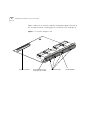
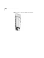
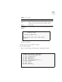
You can install an OC-3/STM-1 daughter card or an OC-12/STM-4
daughter card in either the right pair or the left pair of cutouts of the
ATM Interface Carrier Module (Figure 2). However, if you are installing a
single OC-3/STM-1 card or a single OC-12/STM-4 card, 3Com
recommends installing it in the left cutouts, which are shipped uncovered
for this purpose.
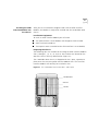
Figure 2
ATM Interface Carrier Module Faceplate Cutouts
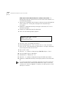
Installation Options
You can install daughter cards into the ATM Interface Carrier Module in
many different combinations. Each cutout of the ATM Interface Carrier
Module can hold an OC-3/STM-1 or an OC-12/STM-4 daughter card.
These daughter cards can be ordered in either single or multi-mode, and
can be mixed and matched accordingly. Furthermore, the OC-3/STM-1
daughter card can also be ordered with one port set to single-mode and
three ports set to multi-mode. The faceplate of the OC-3/STM-1 and
OC-12/STM-4 clearly display if they are multi-mode or single-mode. The
transmitting port (labeled Tx) has the letters SM for single mode or MM
for multi-mode (Figure 3 and Figure 12). Table 1 shows the different
configuration options.
Left Daughter Card Cutouts Right Daughter Card Cutouts

8
ATM I
NTERFACE
M
ODULE
Q
UICK
S
TART
G
UIDE
Ta b le 1
Daughter Card Installation Combinations
Left Cutout Right Cutout
OC-12/STM-4 SM
*
* SM = Single-mode
covered
OC-12/STM-4 MM
†
† MM = Muti-mode
covered
OC-3/STM-1 SM covered
OC-3/STM-1 MM covered
OC-3/STM-1 SM+MM
‡
‡ SM + MM = OC-3/STM-1 daughter card with 1SM port and 3 MM ports.
covered
OC-12/STM-4 SM OC-12/STM-4 SM
OC-12/STM-4 SM
**
**This configuration can be switched (The daughter card in the left cutout can be
put into the right).
OC-12/STM-4 MM
OC-12/STM-4 MM OC-12/STM-4 MM
OC-3/STM-1 SM OC-3/STM-1 SM
OC-3/STM-1 SM
**
OC-3/STM-1 MM
OC-3/STM-1 SM
**
OC-3/STM-1 SM + MM
OC-3/STM-1 MM OC-3/STM-1 MM
OC-3/STM-1 MM
**
OC-3/STM-1 SM + MM
OC-3/STM-1 SM + MM OC-3/STM-1 SM + MM
OC-3/STM-1 SM OC-12/STM-4 SM
OC-3/STM-1 SM
**
OC-12/STM-4 MM
OC-3/STM-1 SM
**
OC-12/STM-4 SM + MM
OC-3/STM-1 MM OC-12/STM-4 MM
OC-3/STM-1 MM
**
OC-12/STM-4 SM + MM
OC-3/STM-1 SM + MM OC-12/STM-4 SM + MM

9
Installation Equipment
To install a daughter card you need:
A #1 phillips-head screwdriver.
The daughter card.
Three flathead countersink phillips screws (included with the daughter
card package).
A tool kit (part number 375B0018-01). Described in Table 2.
Ta b le 2
Tool Kit Contents
Removing the Protective Plate
If you need to install a daughter card in the right pair of cutouts, remove
the protective plate as follows:
1 With a #1 phillips-head screwdriver, remove the three flathead
countersink phillips screws.
2 Push the plate towards the back of the card and remove it.
3 Save the plate and screws for future use.
If you are not installing a daughter card into the right cutout, leave its
protective plate on.
Installing the
OC-3/STM-1
Daughter Card
This section describes how to install a single OC-3/STM-1 daughter card
in the left pair of cutouts (called the “left cutout”). Follow the same
instructions to install a second OC-3/STM-1 daughter card in the right
cutout.
Item
Quantity
(OC-3/STM-1)
Quantity
(OC-12/STM-4)
flathead countersink phillips screws
-
2.5mm diameter, 6mm long
4 4
roundhead phillips screws - 3.0mm
diameter, 6mm long
2 3
flat washers
2 1
spring washers 2 1

10
ATM I
NTERFACE
M
ODULE
Q
UICK
S
TART
G
UIDE
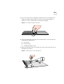
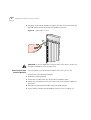
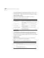
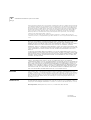
Figure 3 shows an OC-3/STM-1 card with its protective plugs. To install an
OC-12/STM-4 card see “Installing the OC-12/STM-4 Card” on page 16.
Figure 3
OC-3/STM-1 Daughter Card
R
x
T
x
m
m
m
m
1
R
x
T
x
2
3CB9
NAL4MC
R
x
T
x
3
m
m
m
m
R
x
T
x
4
OC3/STM1
Beige Connector Transmitting Port (Tx) Protective Plugs Model Number
(indicates SM or MM)

11
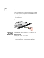
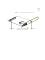
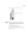
Installation Procedure
There are four spacer posts on the ATM Interface Carrier Module to
support the daughter cards. Two spacers are located directly behind the
left cutout and two are located directly behind the right cutout (Figure 4).
Figure 4
Spacers
Do not remove the spacers from the ATM Interface Carrier Module.
To install the OC-3/STM-1 daughter card in the left cutout, perform the
following procedure:
1 Hold the card at a 20° angle to the ATM Interface Carrier Module with
the protective plugs facing forward and the beige connector on the
bottom.
Spacers

12
ATM I
NTERFACE
M
ODULE
Q
UICK
S
TART
G
UIDE
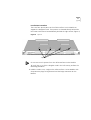
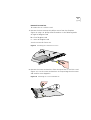
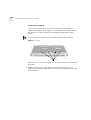
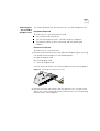
2 Insert the protective plugs into the left cutout from the back of the ATM
Interface Carrier Module (Figure 5) until the 3 front holes of the daughter
card are aligned with the 3 holes in the faceplate of the ATM Carrier
Module.
Figure 5
Inserting the OC-3/STM-1 Card into the Cutouts
3 Lower the OC-3/STM-1 card until the card rests on the spacers,
4 Look from the side of the ATM Interface Carrier Module and align the
beige connector of the ATM Interface Carrier Module with the beige
connector of the OC-3/STM-1 card.

13
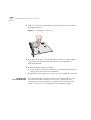
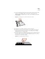
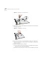
5 Place your fingers on the daughter card directly over the middle of the
beige connector and press down to fasten the connectors together
(Figure 6). A click is heard when the connectors engage.
Figure 6
Fastening the Beige Connectors
6 Insert the following screw and washer combination in the two holes on
the daughter card (Figure 7):
a 1 flat washer
b 1 spring washer
c 1 roundhead phillips screw
7 Repeat the operation for the second hole. Spare screws and washers are
provided in the tool kit.
Figure 7
Replacing the Screws and Washers
click

14
ATM I
NTERFACE
M
ODULE
Q
UICK
S
TART
G
UIDE
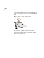
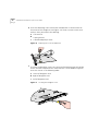
8 To secure the daughter card, insert the three flathead countersink phillips
screws into the faceplate of the ATM Interface Carrier Module (Figure 8).
Insert the screws in the following order:
a Center of daughter card
b Right of daughter card
c Left of daughter card
Figure 8
Securing the Daughter Card
Removing the
OC-3/STM-1
Daughter Card
This section describes how to remove the OC-3/STM-1 daughter card.
Equipment Required
To remove the OC-3/STM-1 card you need:
A #1 phillips-head screw driver
The anti-static bag that the OC-3/STM-1 card was shipped in
The protective plate (if you are removing and not replacing the
module)
3CB8AK2
1
1
1
2
2
2
3
3
4
4

15
Removal Instructions
To remove the OC-3/STM-1 card:
1
Remove the three countersink phillips screws from the faceplate
(Figure 9) using a #1 phillips-head screwdriver in the following order:
a
Right of daughter card
b
Left of daughter card
c
Center of daughter card
Save the screws for future use.
Figure 9
Removing the Countersink Screws
2
Remove the screws and washers from the top of the OC-3/STM-1 card
(Figure 10). Put the screws and washers in the part bag that the screws
and washers were shipped in.
Figure 10
Removing the Screws and Washers
3CB8AK2
1
1
1
2
2
2
3
3
4
4

16
ATM I
NTERFACE
M
ODULE
Q
UICK
S
TART
G
UIDE
3
Hold the OC-3/STM-1 card and gently lift upwards until the connectors
disengage (Figure 11).
Figure 11
Disengaging the Connectors
4
Raise the back of the OC-3/STM-1 daughter card to a 20° angle (approx.),
and remove the card from the ATM Interface Carrier Module in a
backwards direction.
5
Replace the protective plate as follows:
a
Insert the plate into the ATM Interface Carrier Module from the back,
taking care to cover the cutout completely.
b
Replace the three countersink screws that are included with the plate.
Installing the
OC-12/STM-4 Card
This section describes how to install an OC-12/STM-4 daughter card in
the left pair of cutouts (called the “left cutout”). Follow the same
instructions to install a second OC-12/STM-4 card in the right cutout.
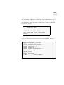
Figure 12 shows an OC-12/STM-4 card with its protective plugs.

17
Figure 12
OC-12/STM-4 Daughter Card with Protective Plug
3CB9
NAK1MC
m
m
R
x
T
x
4
OC12/STM4
Model NumberPort With ProtectiveTransmitting Port (Tx)Beige Connector
Plug RemovedIndicates SM or MM

18
ATM I
NTERFACE
M
ODULE
Q
UICK
S
TART
G
UIDE
Installation Procedure
There are four spacer posts on the ATM Interface Carrier Module to
support the daughter cards (Figure 13). Two spacers are located directly
behind the left cutout and two are located directly behind the right
cutout.
Do not remove the spacers from the ATM Interface Carrier Module.
Figure 13 Spacers
To install the OC-12/STM-4 card in the left cutout perform the following
procedure:
1
Hold the card at a 20° angle (approx.) to the ATM Interface Carrier
Module with the protective plugs facing forward and the beige connector
on the bottom
Spacers

19
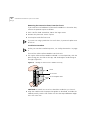
2
Insert the protective plug into the left cutout from the back of the ATM
Interface Carrier Module (Figure 14) until the 3 front holes of the
daughter card are aligned with the 3 holes in the faceplate of the ATM
Carrier Module.
Figure 14 Inserting the OC-12/STM-4 Card into the Cutouts
3
Lower the OC-12/STM-4 card until it rests on the spacer.
4
Look from the side of the ATM Interface Carrier Module and align the
beige connector of the ATM Interface Carrier Module with the beige
connector of the OC-12/STM-4 card.
5
Place your fingers on the daughter card directly over the beige connector
and press down to fasten the connectors together (Figure 15). A click is
heard when the connectors engage.
Figure 15 Fastening the Beige Connectors

20
ATM I
NTERFACE
M
ODULE
Q
UICK
S
TART
G
UIDE
6
Insert the following screw and washer combination in the one hole on
the center of the daughter card (Figure 16) There are more screws and
washers than you need in the tool bag:
a
1 flat washer
b
1 spring washer
c
1 roundhead phillips screw
Figure 16 Replacing the Screw and Washers
7
To secure the daughter card, insert the three flathead countersink phillips
screws into the faceplate of the ATM Interface Carrier Module (Figure 8).
Insert the screws in the following order:
a
Center of daughter card
b
Right of daughter card
c
Left of daughter card
Figure 17 Securing the Daughter Card
3CB8AK2
1
1
1
2
2
2
3
3
4
4
La page est en cours de chargement...
La page est en cours de chargement...
La page est en cours de chargement...
La page est en cours de chargement...
La page est en cours de chargement...
La page est en cours de chargement...
La page est en cours de chargement...
La page est en cours de chargement...
La page est en cours de chargement...
La page est en cours de chargement...
La page est en cours de chargement...
La page est en cours de chargement...
La page est en cours de chargement...
La page est en cours de chargement...
La page est en cours de chargement...
La page est en cours de chargement...
La page est en cours de chargement...
La page est en cours de chargement...
La page est en cours de chargement...
La page est en cours de chargement...
La page est en cours de chargement...
La page est en cours de chargement...
La page est en cours de chargement...
La page est en cours de chargement...
La page est en cours de chargement...
La page est en cours de chargement...
La page est en cours de chargement...
La page est en cours de chargement...
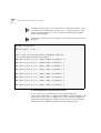
-
 1
1
-
 2
2
-
 3
3
-
 4
4
-
 5
5
-
 6
6
-
 7
7
-
 8
8
-
 9
9
-
 10
10
-
 11
11
-
 12
12
-
 13
13
-
 14
14
-
 15
15
-
 16
16
-
 17
17
-
 18
18
-
 19
19
-
 20
20
-
 21
21
-
 22
22
-
 23
23
-
 24
24
-
 25
25
-
 26
26
-
 27
27
-
 28
28
-
 29
29
-
 30
30
-
 31
31
-
 32
32
-
 33
33
-
 34
34
-
 35
35
-
 36
36
-
 37
37
-
 38
38
-
 39
39
-
 40
40
-
 41
41
-
 42
42
-
 43
43
-
 44
44
-
 45
45
-
 46
46
-
 47
47
-
 48
48


3com CoreBuilder 9000 ATM Interface Module Guide de démarrage rapide
- Taper
- Guide de démarrage rapide
dans d''autres langues
Documents connexes
Autres documents
-
HP 3C905B-TX Manuel utilisateur
-
Sagem 155C Manuel utilisateur
-
Multitech MTQ-MNA1-B01-SP Mode d'emploi
-
Cisco Systems Network Hardware 15454 Manuel utilisateur
-
Multitech MTQ-LAT3-B02.R2 Mode d'emploi
-
Multitech MTQ-H5-B01 Mode d'emploi
-
Dell Precision 7750 Le manuel du propriétaire
-
 Triton Systems RL5000XP Series Le manuel du propriétaire
-
Dell Precision 7550 Le manuel du propriétaire
-
Lenovo UNDP-1 Manuel utilisateur
