La page est en cours de chargement...

MODEL RL5000
XP
PC-basED aTM
INsTaLLaTION GUIDE
VERSION 1.0
TDN 07102-00058 Oct 31 2008
COPYRIGHT NOTICE
© 2006 Delaware Capital Formation, Inc. All Rights Reserved. TRITON, TRITON
WHERE MONEY COMES FROM, TRITON WAVES, DOVER and the DOVER logo
are registered trademarks of Delaware Capital Formation, Inc., a wholly-owned subsid-
iary of Dover Corporation.
CORPORaTE HEaDqUaRTERs: RMa (RETURN MaTERIaL aUTHORIza-
TION)
RETURN aDDREss:
522 E. Railroad Street 21405 Avenue “B”
Long Beach, MS 39560 Long Beach, MS 39560
Phone: (228) 868-1317
Fax: (228) 868-0437

2
WHaT’s IN THIs INsTaLLaTION GUIDE
This Installation Guide gives step-by-step procedures for completing the physical
installation of a Triton RL5000
XP
. This guide covers cabinet and dispenser instal-
lation (if applicable) for RL5000
XP
units equipped with an NMD-100 dispensing
mechanism. The Installation Guide is divided into the following sections:
COMPLIaNCE NOTIfICaTIONs.
aTM INsTaLLaTION fOR aCCEssIbILITy. Describes the basic Americans
with Disabilities Act (ADA) requirements for ATM location and access.
Note: These are the general requirements that should be applicable to most
installation locations. Please verify the specic requirements with the state
where the ATM is to be installed prior to installation. For state contact
information, you may call the ADA information line at 1-800-514-0301.
aTM ENvIRONMENTaL PRECaUTIONs CHECkLIsT. Describes the general
environmental precautions considered when installing the ATM. To help
ensure proper operation of the ATM, ensure the environmental criteria listed
in this checklist are met.
CabINET INsTaLLaTION - sTaNDaRD aNCHORs. Describes how to install the
ATM cabinet using standard (steel) anchor bolts.
CabINET INsTaLLaTION - CHEMICaL bOLTs. Describes how to install the ATM
cabinet using a chemical anchoring process. Note that to install the cabinet
according to these instructions you must purchase the optional chemical
anchor install kit (Part Number 06200-00060).
POWER aND COMMUNICaTION. Describes how to connect the ATM to the
facility power and Ethernet connections.
DIsPENsING MECHaNIsM INsTaLLaTION. Describes how to install the NMD-
100 dispensing mechanism into the ATM security cabinet.
RL5000
XP
INsTaLLaTION GUIDE

3
fEDERaL COMMUNICaTIONs COMMIssION (fCC) COMPLIaNCE
Statement of Compliance: This equipment complies with Part 68 of the FCC
rules. Located in the control area of the Automated Teller Machine (ATM)
is the product label. This label lists the FCC registration number and ringer
equivalence number of the unit. If requested, this information must be provided
to the telephone company. USCO/FIC Codes: When ordering service from the
telephone company for the RL5000
XP
ATM, the following information should
be supplied:
Universal Service Order Code (USOC): RJ-11C
The Facility Interface Code (FIC): 02LS2
Plug and Jack: The plug and jack used to connect this equipment to premise wiring
and telephone network must comply with the applicable FCC Part 68 rules and
requirements adopted by ACTA. A compliant telephone cord and modular plug
is provided with this product. The telephone cord is designed to be connected
to a compatible modular jack that is also compliant.
Ringer Equivalent Number (REN): The REN is used to determine the number
of the devices that may be connected to a telephone line. Excessive RENs on a
telephone line may result in the devices not ringing in response to an incoming
call. In most but not all areas, the sum of the RENs should not exceed ve (5). To
be certain of the number devices that may be connected to a line, as determined
by the local RENs, contact the local telephone company.
RL5000
XP
INsTaLLaTION GUIDE
** CAUTION **
Changes or modications not expressly approved by Triton
Systems could void the regulatory compliance approval
and the warranty. Use of this product in a manner other
than those described in this manual may result in personal
injury!
DIsCLaIMER
The manufacturer of the Automated Teller Machine (ATM) product(s) described
herein makes no representations or warranties, either expressed or implied, by or
with respect to anything in this manual, and shall not be liable for any implied
warranties of tness for a particular purpose or for any indirect, special, or
consequential damages. Information in this document is subject to change without
notice and does not represent a commitment on the part of the manufacturer.

4
If the equipment is causing harm to the network, the telephone company may
request that you disconnect the equipment until the problem is resolved. Repairs
should be made only by qualied factory representatives.
Party Lines: The RL5000
XP
ATM must not be used on party lines.
Alarm Equipment: The RL5000
XP
ATM should have its own dedicated phone
line. Do not install the RL5000
XP
on the same line as alarm equipment.
Electrical Safety Advisory: Telephone companies report that electrical surges,
typically lightening transients, are very destructive to customer equipment
connected to AC power sources. This has been identied as a major nationwide
problem. A commercially available, power surge suppressor, is recommended for
use with the RL5000
XP
to minimize damage in the event of an electrical surge.
CaNaDIaN IC COMPLIaNCE
NOTICE:
The Industry Canada label identies certied equipment. This certication means
that the equipment meets telecommunications network protective, operational
and safety requirements as prescribed in the appropriate terminal equipment
technical requirements document(s). The department does not guarantee the
equipment will operate to the user’s satisfaction.
RL5000
XP
INsTaLLaTION GUIDE
Harm to the Network: If the RL5000
XP
ATM causes harm to the telephone
network, the telephone company will notify the customer that a temporary
discontinuous of service may be required. If advanced notice is not possible,
the telephone company will notify the customer as soon as possible. You will be
advised of your right to le a complaint with the FCC if you believe it’s necessary.
Notication of Changes in Telephone Company Equipment: The telephone
company may make changes in its facilities, equipment, operations, or procedures
that could affect the operation of the equipment. If this happens, the telephone
company will provide advanced notice in order for you to make necessary
modications to maintain uninterrupted service.
Repairs and Returns: If telecom compatibility trouble is experienced with the
RL5000
XP
ATM, you may contact for repairs and warranty information: Triton
at 1-228-868-1317
Triton Systems of Delaware, Inc.
522 East Railroad Street
Long Beach, MS 39560

5
avIs:
L’étiquette d’Industrie Canada identic le matériel homologué. Cette étiquette
certie que le matériel est conforme aux normes de protection, d’exploitation et
de sécurité des réseaux de télécommunications, comme le prescrivent les docu-
ments concernant les exigences techniques relatives au matériel terminal. Le
Ministère n’assure toutefois pas que le matériel fonctionnera à la satisfaction
de l’utilisateur.
Avant d’installer ce matériel, l’utilisateur doit s’assurer qu’il est permis de le
raccorder aux installations de 1’entreprise locale de télécommunication. Le
matériel doit également être installé en suivant une méthode acceptée de rac-
cordement. L’abonné ne doit pas oublier qu’il est possible que la comformité
aux conditions énoncées ci-dessus n’empêche pas la dégradation du service dans
certaines situations.
Les réparations de matériel homologué doivent être coordonnées par un représent-
ant désigné par le fournisseur. L’entreprise de télécommunications peut demander
à I’utilisateur de débrancher un appareil à la suite de réparations ou de modica-
tions effectuées par l’utilisateur ou à cause de mauvais fonctionnement.
RL5000
XP
INsTaLLaTION GUIDE
Before installing this equipment, users should ensure that it is permissible to
be connected to the facilities of the local telecommunications company. The
equipment must also be installed using an acceptable method of connection. The
customer should be aware that compliance with the above conditions may not
prevent degradation of service in some situations.
Repairs to certied equipment should be coordinated by a representative desig-
nated by the supplier. Any repairs or alterations made by the user to this equip-
ment or equipment malfunctions may give the telecommunications company
cause to request the user to disconnect the equipment.
Users should ensure for their own protection that the electrical ground connections
of the power utility, telephone lines and internal metallic water pipe system, if
present, are connected together. This precaution may be particularly important
in rural areas. Caution: Users should not attempt to make such connections
themselves, but should contact the appropriate electric inspection authority or
electrician as appropriate.
NOTICE:
The Ringer Equivalence Number (REN) assigned to each terminal device
provides an indication of the maximum number of terminals allowed to be con-
nected to a telephone interface. The termination on an interface may consist of
any combination of devices subject only to the requirement that the sum of the
RENs of all the devices does not exceed 5.

6
RL5000
XP
INsTaLLaTION GUIDE
Pour sa propre protection, l’utilisateur doit s’assurer que tous les ls de mise à la
terre de la source d’énergie électrique, des lignes téléphoniques et des canalisa-
tions d’eau métalliques, s’ y en a, sont raccordés ensemble. Cette précaution est
particulièrement importante dans les régions rurales. Avertissement: L’utilisateur
ne doit pas tenter de faire ces raccordements lui-même; il doit avoir recours à an
service d’inspection des installations électriques, ou à un électricien, selon le cas.
EMIssIONs (EMI)
Us REqUIREMENTs
This device complies with Part 15 of the FCC rules. Operation is subject to the
following two (2) conditions:
1) This device may not cause harmful interference.
2) This device must accept any interference received, including interference that
may cause undesired operation.
NOTE:
This equipment has been tested and found to comply with the limits for a Class
A digital device pursuant to Part 15 of FCC Rules. These limits are designed to
provide reasonable protection against harmful interference when the equipment is
operated in a commercial environment. This equipment generates, uses, and can
radiate radio frequency energy and, if not installed and used in accordance with
the instruction manual may cause harmful interference to radio communications.
Operation of this equipment in a residential area is likely to
avIs:
L’indice d’équivalence de la sonnerie (IES) assigné à chaque dispositif termi-
nal indique le nombre maximal de terminaux qui peuvent étre raccordés à une
interface. La terminaison d’une interface téléphonique peut consister en une
combinaison de quelques dispositifs, à la seule condition que la somme d’indices
d’équivalence de la sonnerie de tous les dispositifs n’exède pas 5.
UNITED kINGDOM
This equipment has been approved in accordance with Council Decision 98/482/
EC for pan-European single terminal connection to the Public Switched Tele-
phone Network (PSTN). However, due to differences between the individual
PSTNs provided in the different countries, the approval does not, of itself,
give unconditional assurance of successful operation on every PSTN network
termination point. In the event of problems, contact your equipment supplier
in the rst instance. This unit uses only Dual-Tone Multi-Frequency (DTMF)
address signaling.

7
CaNaDIaN REqUIREMENTs
This digital apparatus does not exceed the Class A limits for radio noise emissions
from digital apparatus set in the Radio Interference Regulations of the Canadian
Department of Communications. This Class A digital apparatus complies with
Canadian ICES-003.
Le present appareil numerique n’emet pas de bruits radioelectriques depassant
les limites applicables aux appareils numeriques de la Class A prescrites dans
le Reglement sur le brouillage radioelectrique edicte par le ministere des
Communications du Canada. Cet appareil numerique de la classe A est conforme
a la norme NMB-003 Canada.
Uk REqUIREMENTs
WaRNING:
This is a Class A product. In a domestic environment, this product may cause
radio interference in which case the user may be required to take adequate
measures.
cause harmful interference in which case the user will be required to correct
the interference at his own expense. Changes or modications to this unit not
expressly approved by the party responsible for compliance could void the user’s
authority to operate the equipment.
RL5000
XP
INsTaLLaTION GUIDE

8
RL5000
XP
INsTaLLaTION GUIDE
THIs PaGE INTENTIONaLLy LEfT bLaNk

9
aTM INsTaLLaTION fOR aCCEssIbILITy

10
aTM INsTaLLaTION fOR aC-
CEssIbILITy
1. This document supercedes all
other information provided by
Triton for ATM installation for
accessibility.
2. Information provided in this man-
ual is based on federal guidelines
(ADA Accessibility Guidelines
for Buildings and Facilities –
ADAAG), as amended through
January 1998. You should verify
it has not been amended. States
may also have accessibility codes.
These codes may be more restric-
tive than the federal guidelines.
Please verify this with the state
where the ATM is to be installed
prior to installation. For state
contact information, you may
call the ADA information line at
1-800-514-0301.
3. For countries other than the US,
please use the guidelines for ac-
cessibility for that country.
4. A complete copy of the ADAAG
referred to here can be found at
http://www.access-board.gov.
Included in this document is
the section of the ADAAG spe-
cically for ATMs. For additional
information on oor surfaces and
other ADAAG requirements,
please see the complete specica-
tion.
4.34 Automated Teller Machines.
4.34.1 General. Each automated
teller machine required to be
accessible by 4.1.3 (Accessible
Buildings:New Construction)
shall be on an accessible route
and shall comply with 4.34 (Au-
tomated Teller Machines).
4.34.2 Clear Floor Space. The
automated teller machine shall be
located so that clear oor space
complying with 4.2.4 (Clear
Floor or Ground Space for
Wheelchairs) is provided to al-
low a person using a wheelchair
to make a forward approach, a
parallel approach, or both to the
machine.
4.34.3 Reach Ranges.
(1) Forward Approach Only. If
only a forward approach is possible,
operable parts of all controls shall be
placed within the forward reach range
specied in 4.2.5 (Forward Reach).
(2) Parallel Approach Only. If only
a parallel approach is possible, oper-
able parts of controls shall be placed
as follows:
(a) Reach Depth Not More Than
10 inches (255 mm). Where the reach
depth to the operable parts of all con-
trols as measured from the vertical
plane perpendicular to the edge of the
unobstructed clear oor space at the
farthest protrusion of the automated
teller machine or surround is not
more than 10 inches (255 mm), the
maximum height above the nished
oor or grade shall be 54 inches (1370
mm).
RL5000
XP
INsTaLLaTION GUIDE

11
aTM INsTaLLaTION fOR aCCEssIbILITy
(b) Reach Depth More Than 10
inches (255 mm). Where the reach
depth to the operable parts of any
control as measured from the vertical
plane perpendicular to the edge of the
unobstructed clear oor space at the
farthest protrusion of the automated
teller machine or surround is more
than 10 inches (255 mm), the maxi-
mum height above the nished oor
or grade shall be as follows:
(3) Forward and Parallel Ap-
proach. If both a forward and parallel
approach are possible, operable parts
of controls shall be placed within at
least one of the reach ranges in para-
graphs (1) or (2) of this section.
ACCESSIBILITY SPECIFICATIONS
REACH DEPTH MAXIMUM HEIGHT
Inches Millimeters Inches Millimeters
10 255 54 1370
11 280 53 1/2 1360
12 305 53 1345
13 330 52 1/2 1335
14 355 51 1/2 1310
15 380 51 1295
16 405 50 1/2 1285
17 430 50 1270
18 455 49 1/2 1255
19 485 49 1245
20 510 48 1/2 1230
21 535 47 1/2 1205
22 560 47 1195
23 585 46 1/2 1180
24 610 46 1170
EXCEPTION: Where a function
can be performed in a substantially
equivalent manner by using an alter-
nate control, only one of the controls
needed to perform that function is
required to comply with this section.
If the controls are identied by tactile
markings, such markings shall be
provided on both controls.
4.34.4 Controls. Controls for user
activation shall comply with 4.27.4
(Operation).
4.34.5 Equipment for Persons
with Vision Impairments. Instruc-
tions and all information for use shall
be made accessible to and indepen-
dently usable by persons with vision
impairments.
(20) Where automated teller
machines (ATMs) are provided, each
ATM shall comply with the require-
ments of 4.34 (Automated Teller
Machines) except where two or more
are provided at a location, then only
one must comply.
EXCEPTION: Drive-up-only auto-
mated teller machines are not required
to comply with 4.27 (Controls and
Operating Mechanisms and 4.34.3
(Reach Ranges).
(4) Bins. Where bins are provided
for envelopes, waste paper, or other
purposes, at least one of each type pro-
vided shall comply with the applicable
reach ranges in paragraph (1), (2), or
(3) of this section.

12
4.2.4.2 Relationship of Maneuver-
ing Clearance to Wheelchair Spaces.
One full unobstructed side of the clear
oor or ground space for a wheelchair
shall adjoin or overlap an accessible
route or adjoin another wheelchair
clear oor space. If a clear oor space
is located in an alcove or otherwise
conned on all or part of three sides,
additional maneuvering clearances
shall be provided as shown in Fig. 4(d)
and 4(e).
4.2.4.3 Surfaces for Wheelchair
Spaces. Clear oor or ground spaces
for wheelchairs shall comply with 4.5.
4.2.5 Forward Reach. If the
clear oor space only allows forward
approach to an object, the maximum
high forward reach allowed shall be
48 inches (1220 mm) (see Fig. 5(a)).
The minimum low forward reach is 15
inches (380 mm). If the high forward
reach is over an obstruction, reach and
clearances shall be as shown in Fig.
5(b).
Figure 4a. Clear oor space.
Figure 4b. Forward approach.
Figure 4c. Parallel approach.
RL5000
XP
INsTaLLaTION GUIDE
4.2.4 Clear Floor or Ground
Space for Wheelchairs.
4.2.4.1 Size and Approach. The
minimum clear oor or ground space
required to accommodate a single,
stationary wheelchair and occupant
is 30 inches by 48 inches (760 mm by
1220 mm) (see Fig. 4a). The minimum
clear oor or ground space for wheel-
chairs may be positioned for forward
or parallel approach to an object (see
Fig. 4b and 4c). Clear oor or ground
space for wheelchairs may be part of
the knee space required under some
objects.

13
For a front approach, where the depth
of the alcove is equal to or less than
24 inches (610 mm), the required clear
oor space is 30 inches by 48 inches
(760 mm by 1220 mm).
For a side approach, where the depth
of the alcove is equal to or less than
15 inches (380 mm), the required clear
oor space is 30 inches by 48 inches
(760 mm by 1220 mm).
Figures 4d. Clear floor space in
alcoves.
For a front approach, if the depth of
the alcove is greater than 24 inches
(610 mm), then in addition to the 30-
inch (760 mm) width, a maneuvering
clearance of 6 inches (150 mm) in
width is required.
For a side approach, where the depth
of the alcove is greater than 15 inches
(380 mm), then in addition to the 48-
inch (1220 mm) length, an additional
maneuvering clearance of 12 inches
(350 mm) is required.
Figures 4e. Clear floor space in
alcove.
aTM INsTaLLaTION fOR aCCEssIbILITy
4.2.6 Side Reach. If the clear oor space allows parallel approach by a person
in a wheelchair, the maximum high side reach allowed shall be 54 inches (1370
mm) and the low side reach shall be no less than 9 inches (230 mm) above the
oor (Fig. 6(a) and 6(b)). If the side reach is over an obstruction, the reach and
clearances shall be as shown in Fig 6(c).

14
Figure 6b. Parallel approach - high/
low side reach.
Figure 5a. Forward reach, unobstructed.
Figure 5b. Forward reach, obstructed.
RL5000
XP
INsTaLLaTION GUIDE
Figure 6a. Parallel approach - side
reach.

15
aTM INsTaLLaTION fOR aCCEssIbILITy
Figure 6c. Side reach, obstructed.
RL5000
XP
ADA requirements.

16
THIs PaGE INTENTIONaLLy LEfT bLaNk
RL5000
XP
INsTaLLaTION GUIDE

17
aTM ENvIRONMENTaL PRECaUTIONs
CHECkLIsT

18
aTM ENvIRONMENTaL PRECaUTIONs CHECkLIsT
TEMPERATURE/HUMIDITY
1. The ATM needs to be in an
environmentally-controlled
location, with no extreme uc-
tuations in temperature or
humidity.
Generally, these parameters
must fall within the following
ranges:
Temperature
• 10-40 Deg. C
• 50-104 Deg. F
Relative Humidity
• 20% - 80%
• (Non-Condensing)
AC POWER REQUIREMENTS
2. Ensure the following AC power
requirements are met:
Isolated Ground. An equipment
grounding conductor that is insulated
from the conduit or raceway and all
other grounding points throughout
its entire length. The only points of
electrical connection will be at the
duplex outlet and service panel ends
of the line.
Dedicated source. The ATM AC
power feed will be a dedicated line, to
which no other electrical devices are
connected. The ATM power line will
be wired for a single “duplex”-style
outlet and connected directly to the
AC service panel.
DEDICATED TELEPHONE
3. Ensure the following telephone-
line requirements are met:
Dedicated line. The telephone line
servicing the ATM will not be a
“party” line or any other shared type
connection.
Proximity to Interference Sources.
The telephone line must not be in
close proximity to “noisy” devices
that could induce interference into the
ATM communications channel.
Current (Max)
• 5.05A @ 120V
• 2.01A @ 240V
Voltage
• 90V - 136V @ 50/60 Hz
• 198V - 257V @ 50/60 Hz
Power Consumption (Idle)
• 2.0A @ 115 VAC at 60 Hz
• 1.0A @ 230 VAC at 50 Hz
Power Consumption (Max Load)
• 606 Watts @ 120V
• 482 Watts @ 240V
RF INTERFERENCE
4. Ensure there are no devices
near the terminal that may
cause RF interference, such as:
TVs Coolers
Security Devices
Neon Signs
Devices with Compressors
When installing an ATM, some general environmental precautions
need to be considered. Evaluate the location where the ATM will be
installed. To help ensure proper operation of the ATM, ensure the
environmental criteria listed in this checklist are met.

19
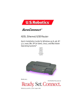
CabINET DIMENsIONs

20
RL5000
XP
INsTaLLaTION GUIDE
Service Area Dimensions
Cabinet Dimensions (Side/Rear Views)
[ 610 ]
24”
Cable Feed
Through
/