Triton Systems FT5000XP Series Le manuel du propriétaire
- Taper
- Le manuel du propriétaire

MODEL FT5000
XP
PC-BASED ATM
INSTALLATION GUIDE
VERSION 1.0
TDN 07102-00059 Mar 24 2009
COPYRIGHT NOTICE
© 2008 Delaware Capital Formation, Inc. All Rights Reserved. TRITON, TRITON
WHERE MONEY COMES FROM, TRITON WAVES, DOVER and DOVER logo are
registered trademarks of Delaware Capital Formation, Inc., a wholly-owned subsidiary
of Dover Corporation.
CORPORATE HEADQUARTERS: RMA (RETURN MATERIAL AUTHORIZATION)
R
ETURN ADDRESS:
522 E. Railroad Street 21405 Avenue “B”
Long Beach, MS 39560 Long Beach, MS 39560
PHONE: (228) 868-1317
FAX: (228) 868-0437

2
WHAT’S IN THIS INSTALLATION GUIDE
This Installation Guide provides information for the preparation and installa-
tion of the FT5000
XP
ATM. It contains requirements for site preparation, electri-
cal specifications, and cabinet accessibility that comply with all relevant codes,
laws and regulations. The Installation Guide is divided into the following sec-
tions:
COMPLIANCE NOTIFICATIONS.
ATM INSTALLATION FOR ACCESSIBILITY. Describes the basic Americans with
Disabilities Act (ADA) requirements for ATM location and access. Note:
These are the general requirements that should be applicable to most
installation locations. Please verify the specific requirements with the state
where the ATM is to be installed, prior to installation. For state contact
information, you may call the ADA information line at 1-800-514-0301.
ATM E NVIRONMENTAL P RECAUTIONS C HECKLIST. Describes the general
environmental precautions considered when installing the ATM. To help
ensure proper operation of the ATM, ensure the environmental criteria
listed in this checklist are met.
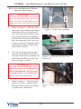
SITE PREPARATION/INSTALLATION. Describes site preparation for exterior wall
or vestibule locations. Instructions provide dimensions of the unit and
clearances needed for operability/serviceability. Physical installation of
the cabinet and front trim is described as well as raising/leveling of unit, if
needed.
POWER AND COMMUNICATION. Describes how to connect the ATM to the
facility power and Ethernet connections.
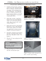
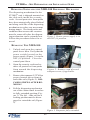
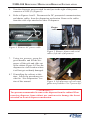
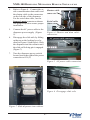
DISPENSING MECHANISM INSTALLATION. Describes how to install/remove the
dispensing mechanism into the ATM security cabinet.
FT5000
XP
- SITE PREPARATION AND INSTALLATION GUIDE

3
FT5000
XP
- SITE PREPARATION AND INSTALLATION GUIDE
INTRODUCTION
This document contains the information necessary for the preparation and in-
stallation of an FT5000
XP
Triton ATM. It’s important that the site complies with
the requirements specified in this document. In addition, electrical wiring and
mechanical systems must also comply with all relevant laws and regulations.
The site must be prepared by the customer or his agent who is fully conversant
with the requirements of installing through-the-wall ATM equipment. The re-
sponsibility for ensuring that the site is prepared in compliance with this docu-
ment remains with the customer.
For information and guidance only, a list is provided in general terms of those
matters for which the customer is responsible. The list is not intended to be
comprehensive and in no way modifies, alters, or limits the responsibility of the
customer for all aspects of adequate site preparation.
1. Location of the equipment and site preparation.
2. Site wiring (power, communication).
3. Location of other equipment that may cause electrical, electromagnetic
or heat induced interference.
4. Make building alterations to meet wiring and other site requirements.
5. Install all communication cables, wall jacks, and associated hardware.
6. Provide and install necessary power distribution boxes, conduits and
grounds.
7. Ensure all applicable codes, regulations and laws (electrical, building,
safety) are adhered to.
8. Ensure the environmental requirements of this unit are met.
9. Install the unit at a height which meets the ADA accessibility regula-
tions for the state/country installed.

4
FEDERAL COMMUNICATIONS COMMISSION (FCC) COMPLIANCE
Statement of Compliance: This equipment complies with Part 68 of the FCC rules.
Located in the control area of the Automated Teller Machine (ATM) is the product
label. This label lists the FCC registration number and ringer equivalence number of
the unit. If requested, this information must be provided to the telephone company.
USCO/FIC Codes: When ordering service from the telephone company for the
FT5000
XP
ATM, the following information should be supplied:
Universal Service Order Code (USOC): RJ-11C
The Facility Interface Code (FIC): 02LS2
Plug and Jack: The plug and jack used to connect this equipment to premise wiring
and telephone network must comply with the applicable FCC Part 68 rules and
requirements adopted by ACTA. A compliant telephone cord and modular plug is
provided with this product. The telephone cord is designed to be connected to a
compatible modular jack that is also compliant.
Ringer Equivalent Number (REN): The REN is used to determine the number of the
devices that may be connected to a telephone line. Excessive RENs on a telephone
line may result in the devices not ringing in response to an incoming call. In most but
not all areas, the sum of the RENs should not exceed five (5). To be certain of the
number devices that may be connected to a line, as determined by the local RENs,
contact the local telephone company.
FT5000
XP
- SITE PREPARATION AND INSTALLATION GUIDE
DISCLAIMER
The manufacturer of the Automated Teller Machine (ATM) product(s) described
herein makes no representations or warranties, either expressed or implied, by or
with respect to anything in this manual, and shall not be liable for any implied
warranties of fitness for a particular purpose or for any indirect, special, or
consequential damages. Information in this document is subject to change
without notice and does not represent a commitment on the part of the
manufacturer.
** CAUTION **
Changes or modifications not expressly approved by Triton
Systems could void the regulatory compliance approval
and the warranty. Use of this product in a manner other
than those described in this manual may result in personal
injury!

5
If the equipment is causing harm to the network, the telephone company may request
that you disconnect the equipment until the problem is resolved. Repairs should be
made only by qualified factory representatives.
Party Lines: The FT5000
XP
ATM must not be used on party lines.
Alarm Equipment: The FT5000
XP
ATM should have its own dedicated phone line.
Do not install the FT5000
XP
on the same line as alarm equipment.
Electrical Safety Advisory: telephone companies report that electrical surges, typically
lightening transients, are very destructive to customer equipment connected to AC
power sources. This has been identified as a major nationwide problem. A
commercially available, power surge suppressor, is recommended for use with the
FT5000
XP
to minimize damage in the event of an electrical surge.
CANADIAN IC COMPLIANCE
NOTICE:
The Industry Canada label identifies certified equipment. This certification means
that the equipment meets telecommunications network protective, operational and
safety requirements as prescribed in the appropriate terminal equipment technical
requirements document(s). The department does not guarantee the equipment will
operate to the user ’s satisfaction.
FT5000
XP
- SITE PREPARATION AND INSTALLATION GUIDE
Harm to the Network: If the FT5000
XP
ATM causes harm to the telephone network,
the telephone company will notify the customer that a temporary discontinuous of
service may be required. If advanced notice is not possible, the telephone company
will notify the customer as soon as possible. You will be advised of your right to file
a complaint with the FCC if you believe it’s necessary.
Notification of Changes in Telephone Company Equipment: The telephone company
may make changes in its facilities, equipment, operations, or procedures that could
affect the operation of the equipment. If this happens, the telephone company will
provide advanced notice in order for you to make necessary modifications to maintain
uninterrupted service.
Repairs and Returns: If telecom compatibility trouble is experienced with the FT5000
XP
ATM, you may contact for repairs and warranty information: Triton at 1-228-868-
1317
Triton Systems of Delaware, Inc.
522 East Railroad Street
Long Beach, MS 39560
Before installing this equipment, users should ensure that it is permissible to be
connected to the facilities of the local telecommunications company . The equip-
ment must also be installed using an acceptable method of connection. The cus-
tomer should be aware that compliance with the above conditions may not prevent
degradation of service in some situations.

6
NOTICE:
The REN assigned to each terminal device provides an indication of the maximum
number of terminals allowed to be connected to a telephone interface. The termina-
tion on an interface may consist of any combination of devices subject only to the
requirement that the sum of the RENs of all the devices does not exceed 5.
AVIS:
L’étiquette d’Industrie Canada identific le matériel homologué. Cette étiquette certifie
que le matériel est conforme aux normes de protection, d’exploitation et de sécurité
des réseaux de télécommunications, comme le prescrivent les documents concernant
les exigences techniques relatives au matériel terminal. Le Ministère n’assure toutefois
pas que le matériel fonctionnera à la satisfaction de l’utilisateur.
Avant d’installer ce matériel, l’utilisateur doit s’assurer qu’il est permis de le raccorder
aux installations de 1’entreprise locale de télécommunication. Le matériel doit
également être installé en suivant une méthode acceptée de raccordement. L’abonné
ne doit pas oublier qu’il est possible que la comformité aux conditions énoncées ci-
dessus n’empêche pas la dégradation du service dans certaines situations.
Les réparations de matériel homologué doivent être coordonnées par un représentant
désigné par le fournisseur. L’entreprise de télécommunications peut demander à
I’utilisateur de débrancher un appareil à la suite de réparations ou de modifications
effectuées par l’utilisateur ou à cause de mauvais fonctionnement.
FT5000
XP
- SITE PREPARATION AND INSTALLATION GUIDE
Repairs to certified equipment should be coordinated by a representative desig-
nated by the supplier. Any repairs or alterations made by the user to this equipment,
or equipment malfunctions, may give the telecommunications company cause to
request the user to disconnect the equipment.
Users should ensure for their own protection that the electrical ground connections
of the power utility, telephone lines, and internal metallic water pipe system, if present,
are connected together. This precaution may be particularly important in rural areas.
Caution: Users should not attempt to make such connections themselves, but should
contact the appropriate electric inspection authority, or electrician, as appropriate.
AVIS:
Pour sa propre protection, l’utilisateur doit s’assurer que tous les fils de mise à la
terre de la source d’énergie électrique, des lignes téléphoniques et des canalisations
d’eau métalliques, s’fl y en a, sont raccordés ensemble. Cette précaution est
particulièrement importante dans les régions rurales. Avertissement: L’utilisateur ne
doit pas tenter de faire ces raccordements lui-même; il doit avoir recours à an service
d’inspection des installations électriques, ou à un électricien, selon le cas.
L’indice d’équivalence de la sonnerie (IES) assigné à chaque dispositif terminal
indique le nombre maximal de terminaux qui peuvent étre raccordés à une interface.
La terminaison d’une interface téléphonique peut consister en une combinaison de
quelques dispositifs, à la seule condition que la somme d’indices d’équivalence de
la sonnerie de tous les dispositifs n’exède pas 5.

7
EMISSIONS (EMI)
This device complies with Part 15 of the FCC rules. Operation is subject to the
following two (2) conditions:
1) This device may not cause harmful interference.
2) This device must accept any interference received, including interference that
may cause undesired operation.
NOTE:
This equipment has been tested and found to comply with the limits for a Class A
digital device, pursuant to Part 15 of FCC Rules. These limits are designed to
provide reasonable protection against harmful interference when the equipment is
operated in a commercial environment. This equipment generates, uses, and can
radiate radio frequency energy and, if not installed and used in accordance with the
instruction manual, may cause harmful interference to radio communications.
Operation of this equipment in a residential area is likely to cause harmful interference
in which case the user will be required to correct the interference at his own expense.
Changes or modifications to this unit not expressly approved by the party responsible
for compliance could void the user’s authority to operate the equipment.
CANADIAN EMISSION REQUIREMENTS
This digital apparatus does not exceed the Class A limits for radio noise emissions
from digital apparatus set in the Radio Interference Regulations of the Canadian
Department of Communications. This Class A digital apparatus complies with
Canadian ICES-003.
FT5000
XP
- SITE PREPARATION AND INSTALLATION GUIDE
UNITED KINGDOM
This equipment has been approved in accordance with Council Decision 98/482/EC
for pan-European single terminal connection to the Public Switched Telephone
Network (PSTN). However, due to differences between the individual PSTNs pro-
vided in the different countries, the approval does not, of itself, give unconditional
assurance of successful operation on every PSTN network termination point. In the
event of problems, contact your equipment supplier in the first instance. This unit
uses only Dual-Tone Multi-Frequency (DTMF) address signaling.
Le present appareil numerique n’emet pas de bruits radioelectriques depassant les
limites applicables aux appareils numeriques de la Class A prescrites dans le Reglement
sur le brouillage radioelectrique edicte par le ministere des Communications du
Canada. Cet appareil numerique de la classe A est conforme a la norme NMB-003
Canada.
UK / AUSTRALIAN EMISSION REQUIREMENTS
WARNING:
This is a Class A product. In a domestic environment this product may cause radio
interference in which case the user may be required to take adequate measures.

THIS PAGE INTENTIONALLY LEFT BLANK
8
FT5000
XP
- SITE PREPARATION AND INSTALLATION GUIDE

9
ATM INSTALLATION FOR ACCESSIBILITY

10
ATM INSTALLATION FOR
ACCESSIBILITY
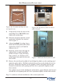
1. This document supersedes all other
information provided by Triton for
ATM installation for accessibility.
2. Information provided in this
manual is based on federal guide-
lines (ADA Accessibility Guidelines
for Buildings and Facilities –
ADAAG) as amended through
January 1998. You should verify it
has not been amended. States may
also have accessibility codes.
These codes may be more restric-
tive than the federal guidelines.
Please verify this with the state
where the ATM is to be installed
prior to installation. For state con-
tact information, you may call the
ADA information line at 1-800-514-
0301.
3. For countries other than the US,
please use the guidelines for ac-
cessibility for that country.
4. A complete copy of the ADAAG
referred to here can be found at
http://www.access-board.gov. In-
cluded in this document is the sec-
tion of the ADAAG specifically for
ATMs. For additional information
on floor surfaces and other
ADAAG requirements, please see
the complete specification.
4.34 Automated Teller
Machines.
4.34.1 General. Each machine re-
quired to be accessible by 4.1.3
(Accessible Buildings: New Con-
struction) shall be on an accessible
route and shall comply with 4.34
(Automated Teller Machines).
4.34.2 Clear Floor Space. The auto-
mated teller machine shall be lo-
cated so that clear floor space com-
plying with 4.2.4 (Clear Floor or
Ground Space for Wheelchairs)
is provided to allow a person using
a wheelchair to make a forward ap-
proach, a parallel approach, or both
to the machine.
4.34.3 Reach Ranges.
(1) Forward Approach Only. If only a
forward approach is possible, operable
parts of all controls shall be placed within
the forward reach range specified in
4.2.5 (Forward Reach).
(2) Parallel Approach Only. If only a
parallel approach is possible, operable
parts of controls shall be placed as fol-
lows:
(a) Reach Depth Not More Than 10
inches (255 mm). Where the reach
depth to the operable parts of all con-
trols as measured from the vertical plane
perpendicular to the edge of the unob-
structed clear floor space at the farthest
protrusion of the automated teller ma-
chine or surround is not more than 10
inches (255 mm), the maximum height
above the finished floor or grade shall
be 54 inches (1370 mm).
FT5000
XP
- SITE PREPARATION AND INSTALLATION GUIDE

11
ATM INSTALLATION FOR ACCESSIBILITY
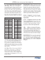
(b) Reach Depth More Than 10 inches
(255 mm). Where the reach depth to
the operable parts of any control as mea-
sured from the vertical plane perpen-
dicular to the edge of the unobstructed
clear floor space at the farthest protru-
sion of the automated teller machine or
surround is more than 10 inches (255
mm), the maximum height above the fin-
ished floor or grade shall be as follows:
(3) Forward and Parallel Approach. If
both a forward and parallel approach
are possible, operable parts of controls
shall be placed within at least one of the
reach ranges in paragraphs (1) or (2) of
this section.
SNOITACIFICEPSYTILIBISSECCA
H T P E DH C A E RTH G I E HMUM I X AM
sehcnI sretemilliM sehcnI sretemilliM
01552450731
110822/ 13 50631
21503355431
310332/ 12 55331
415532/ 11 50131
51083155921
615042/ 10 55821
71034050721
815542/ 19 45521
91584945421
020152/ 18 40321
125352/ 17 45021
22065745911
325852/ 16 40811
42016640711
EXCEPTION: Where a function can be
performed in a substantially equivalent
manner by using an alternate control,
only one of the controls needed to per-
form that function is required to comply
with this section. If the controls are iden-
tified by tactile markings, such markings
shall be provided on both controls.
4.34.4 Controls. Controls for user
activation shall comply with 4.27.4
(Operation).
4.34.5 Equipment for Persons with
Vision Impairments. Instructions and
all information for use shall be made ac-
cessible to and independently usable
by persons with vision impairments.
(20) Where automated teller ma-
chines (ATMs) are provided, each ATM
shall comply with the requirements of
4.34 (Automated Teller Machines) ex-
cept where two or more are provided at
a location, then only one must comply.
EXCEPTION: Drive-up-only automated
teller machines are not required to com-
ply with 4.27 (Controls and Operating
Mechanisms) and 4.34.3 ( Reach
Ranges).
(4) Bins. Where bins are provided for
envelopes, waste paper , or other pur -
poses, at least one of each type pro-
vided shall comply with the applicable
reach ranges in paragraph (1), (2), or (3)
of this section.

12
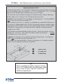
4.2.4.2 Relationship of Maneuvering
Clearance to Wheelchair Spaces. One
full unobstructed side of the clear floor
or ground space for a wheelchair shall
adjoin or overlap an accessible route or
adjoin another wheelchair clear floor
space. If a clear floor space is located in
an alcove or otherwise confined on all
or part of three sides, additional maneu-
vering clearances shall be provided as
shown in Fig. 4(d) and 4(e).
4.2.4.3 Surfaces for Wheelchair
Spaces. Clear floor or ground spaces
for wheelchairs shall comply with 4.5
(Ground and Floor Surfaces).
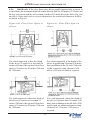
4.2.5 Forward Reach. If the clear
floor space only allows forward ap-
proach to an object, the maximum high
forward reach allowed shall be 48 inches
(1220 mm) (see Fig. 5(a)). The minimum
low forward reach is 15 inches (380 mm).
If the high forward reach is over an ob-
struction, reach and clearances shall be
as shown in Fig. 5(b).
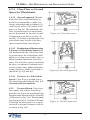
Figure 4a. Clear floor space.
Figure 4b. Forward approach.
Figure 4c. Parallel approach.
FT5000
XP
- SITE PREPARATION AND INSTALLATION GUIDE
4.2.4 Clear Floor or Ground
Space for Wheelchairs.
4.2.4.1 Size and Approach. The mini-
mum clear floor or ground space re-
quired to accommodate a single, sta-
tionary wheelchair and occupant is 30
inches by 48 inches (760 mm by 1220
mm) (see Fig. 4a). The minimum clear
floor or ground space for wheelchairs
may be positioned for forward or paral-
lel approach to an object (see Fig. 4b
and 4c). Clear floor or ground space for
wheelchairs may be part of the knee
space required under some objects.

13
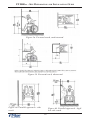
For a front approach, where the depth
of the alcove is equal to or less than 24
inches (610 mm), the required clear floor
space is 30 inches by 48 inches (760 mm
by 1220 mm).
For a side approach, where the depth of
the alcove is equal to or less than 15
inches (380 mm), the required clear floor
space is 30 inches by 48 inches (760 mm
by 1220 mm).
Figures 4d . Clear Floor Space in
Alcoves.
For a front approach, if the depth of the
alcove is greater than 24 inches (610 mm),
then in addition to the 30-inch (760 mm)
width, a maneuvering clearance of 6
inches (150 mm) in width is required.
For a side approach, where the depth of
the alcove is greater than 15 inches (380
mm), then in addition to the 48-inch (1220
mm) length, an additional maneuvering
clearance of 12 inches (350 mm) is
required.
Figures 4e. Clear Floor Space in
Alcove.
ATM INSTALLATION FOR ACCESSIBILITY
4.2.6 Side Reach. If the clear floor space allows parallel approach by a person in
a wheelchair, the maximum high side reach allowed shall be 54 inches (1370 mm) and
the low side reach shall be no less than 9 inches (230 mm) above the floor (Fig. 6(a)
and 6(b)). If the side reach is over an obstruction, the reach and clearances shall be
as shown in Fig 6(c).

14
Figure 6a. Parallel approach - side
reach.
Figure 6b. Parallel approach - high/
low side reach.
Figure 5a. Forward reach, unobstructed.
Figure 5b. Forward reach, obstructed.
FT5000
XP
- SITE PREPARATION AND INSTALLATION GUIDE

15
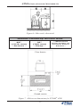
Figure 6c. Side reach, ob structed.
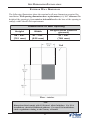
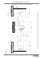
ATM INSTALLATION FOR ACCESSIBILITY
ae rAsseccApac i dnaHed i s t uO
"84
)mm9121 (
- s s o r cA-
"03
)mm267 (
-p e eD-
*
de r usaeM
foretnecmor f
l e n a P l o r t n oC
*a i c s aF
Floor Interior
Figure 7. ADA access dimensions for FT5000
XP
ATM.
Ground exterior

16
THIS PAGE INTENTIONALLY LEFT BLANK
FT5000
XP
- SITE PREPARATION AND INSTALLATION GUIDE

17
ENVIRONMENTAL PRECAUTION CHECKLIST

18
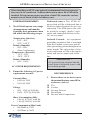
ATM ENVIRONMENTAL PRECAUTIONS CHECKLIST
TEMPERATURE/HUMIDITY
1. The ATM will operate over a range
of temperatures and humidity.
Generally, these parameters must
fall within the following ranges:
Temperature (Interior)
• 10°C - 40°C
• 50°F - 104° F
Relative Humidity
• 20% - 80%
• (Non-Condensing)
Temperature (Exterior)
AC POWER REQUIREMENTS
2. Ensure the following AC power
requirements are met:
Current (Max)
• 5.05A @ 120V
• 2.01A @ 240V
Voltage
• 90V - 136V @ 50/60 Hz
• 198V - 257V @ 50/60 Hz
Power Consumption (Idle)
• 2.0A @ 115 VAC at 60 Hz
• 1.0A @ 230 VAC at 50 Hz
Isolated G round. An equipment
grounding conductor that is insulated
from the conduit or raceway and all
other grounding points throughout its
entire length. The only points of elec-
trical connection will be at the duplex
outlet and service panel ends of the
line.
• -35°C - 50°C
• -30°F - 122°F
Relative Humidity
• 20% - 100%
Dedicated source. The ATMs AC
power feed will be a dedicated line to
which no other electrical devices are
connected. The ATM power line will
be wired for a single “duplex”-style
outlet and connected directly to the
AC service panel.
Power Consumption (Max Load)
• 606 Watts @ 120V
• 482 Watts @ 240V
When installing an ATM, some general environmental and power precau-
tions need to be considered. Evaluate the location where the ATM will be
installed. To help ensure proper operation of the ATM, ensure the environ-
mental criteria listed in this checklist are met.
RF INTERFERENCE
3. Ensure there are no devices near
the terminal that may cause RF in-
terference, such as:
TVs
Coolers
Security Devices
Neon Signs
Devices with Compressors
* IMPORTANT *
AC power for the terminal should
come from a dedicated source with
an isolated ground.

19
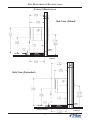
SITE PREPARATION / INSTALLATION

20
FT5000
XP
- SITE PREPARATION AND INSTALLATION GUIDE
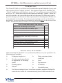
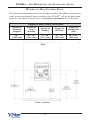
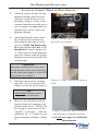
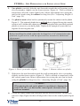
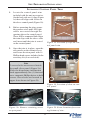
INTRODUCTION
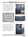
The Triton FT5000
XP
is a self-serviced, weatherized terminal adaptable for any suit-
able exterior wall or vestibule location. The cabinet design allows flexibility for
“Island” installations (wall thickness up to 6-1/4") or existing structures (wall thick-
ness up to 10"). Built-in leveling feet and optional platforms (“plinths”) allow the
unit to be raised to the desired height of the wall opening. The following section
provides the physical dimensions and requirements for installing the FT5000
XP
for
your particular site location. To assist you in preparing your site, a check list is
provided of various procedures that should be carried out prior to the arrival of the
ATM. The Business Hours Cabinet is no longer offered.
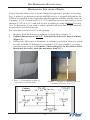
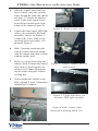
INSTALLATION ACCESSORIES
When installing the FT5000
XP
, it is recommended that you or your agent have the
following items available:
» Lifting/moving device
» Wooden/metal safety blocks
to support the ATM during
install
» Framing square
» Hammer
» Water-resistant sealant
(caulk,etc)
» Level
» Tape measure
» Crowbar(s)
» Circular/Jig saws
T S I LKCEHCNO I T ARAP ERPE T I S
na l pr oo l fang i s eddnae t i st c e l eS
t emsno i t i dnoc l a t nemno r i vnee r usnE
se l udehc sr odne vdnar o t c a r t nochs i l ba t sE
s t neme r i uqe ren i lno i t a c i nummock c ehC
sdeeny rosseccano i t a l l a t sn ina l P
y r assecenekamdnana l pr oo l fkcehC
sno i t a r e t l a
s t neme r i uqe r l ac i r t ce l el l a t sn I
sdeenno i t ac i nummocr o fe t i se r ape rP
) l ano i t po (gn i n i a r t r o t a r epona l P
t s e tdnas en i lno i t a c i nummoc l l a t sn I
e l ba l i avae r ase i rosseccano i t a l l a t sn ie r usnE
» Tool kit consisting of open/ closed box wrenches, magnetic Phillips/flat
screwdrivers, socket set, crescent wrench, pliers, Allen wrench set, etc.
La page est en cours de chargement...
La page est en cours de chargement...
La page est en cours de chargement...
La page est en cours de chargement...
La page est en cours de chargement...
La page est en cours de chargement...
La page est en cours de chargement...
La page est en cours de chargement...
La page est en cours de chargement...
La page est en cours de chargement...
La page est en cours de chargement...
La page est en cours de chargement...
La page est en cours de chargement...
La page est en cours de chargement...
La page est en cours de chargement...
La page est en cours de chargement...
La page est en cours de chargement...
La page est en cours de chargement...
La page est en cours de chargement...
La page est en cours de chargement...
La page est en cours de chargement...
La page est en cours de chargement...
La page est en cours de chargement...
La page est en cours de chargement...
La page est en cours de chargement...
La page est en cours de chargement...
La page est en cours de chargement...
La page est en cours de chargement...
-
 1
1
-
 2
2
-
 3
3
-
 4
4
-
 5
5
-
 6
6
-
 7
7
-
 8
8
-
 9
9
-
 10
10
-
 11
11
-
 12
12
-
 13
13
-
 14
14
-
 15
15
-
 16
16
-
 17
17
-
 18
18
-
 19
19
-
 20
20
-
 21
21
-
 22
22
-
 23
23
-
 24
24
-
 25
25
-
 26
26
-
 27
27
-
 28
28
-
 29
29
-
 30
30
-
 31
31
-
 32
32
-
 33
33
-
 34
34
-
 35
35
-
 36
36
-
 37
37
-
 38
38
-
 39
39
-
 40
40
-
 41
41
-
 42
42
-
 43
43
-
 44
44
-
 45
45
-
 46
46
-
 47
47
-
 48
48


Triton Systems FT5000XP Series Le manuel du propriétaire
- Taper
- Le manuel du propriétaire
dans d''autres langues
Documents connexes
Autres documents
-
3com CoreBuilder 9000 Getting Started Manual
-
MicroNet SP3352 Manuel utilisateur
-
-
 Efficient Networks Network Router 5800 Manuel utilisateur
-
Midmark 630 Human Form® Procedures Chair (-010 thru -013, -020 thru -023) Mode d'emploi
-
 US Robotics SureConnect U.S. Robotics SureConnect ADSL Ethernet/USB Router Manuel utilisateur
-
Miller MW175 Le manuel du propriétaire
-
3com 3C81600 - SuperStack II Enterprise Monitor Manuel utilisateur
-
 PORT CONNECT 901234 Universal Keyed Security Cable Le manuel du propriétaire


