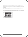
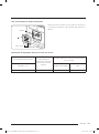
Samsung DOP36M86DLS Guide d'installation
- Catégorie
- Cuisinières
- Taper
- Guide d'installation

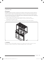
Installation Instructions
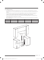
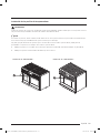
Contemporary Style Pro Range
DOP48M86D**/DOP36M86D**
DG68-01454A-00
INSTALL_DOP48M86D_DG68-01454A-00_EN+MES+CFR.indb 1INSTALL_DOP48M86D_DG68-01454A-00_EN+MES+CFR.indb 1 2022-08-05 오후 5:00:132022-08-05 오후 5:00:13

English2
Contests
Before You Begin 3
Important Notes to the Owner 3
Customer-Assurance Information 3
Important Safety Instructions 4
READ ALL INSTRUCTIONS BEFORE USING THIS APPLIANCE 4
Symbols In This Manual 4
About Anti-Tip Device 4
California Proposition 65 Warning 4
Commonwealth of Massachusetts 4
Installation-Related Safety Instructions 5
Product Specications 10
What Is Included (DOP48M86D**) 10
What Is Included (DOP36M86D**) 11
Needed Tools and Parts 12
Installation Requirements 13
Pre-Installation Checklist 13
General Requirements 13
Location Requirements 16
Gas Requirements 18
Special Gas Requirements (gas models sold in Massachusetts) 18
Electrical Requirements 19
Installation Instructions 20
Preparing for Installation 20
About Oven Functions 27
Installing the Burner-Control Knobs 29
Rangetop Assembly 30
Verifying Proper Operation 34
Removing and Reinstalling the Range 34
Installation Checklist 35
INSTALL_DOP48M86D_DG68-01454A-00_EN+MES+CFR.indb 2INSTALL_DOP48M86D_DG68-01454A-00_EN+MES+CFR.indb 2 2022-08-05 오후 5:00:132022-08-05 오후 5:00:13

English 3
Before You Begin
Important Notes to the Owner
Installer
• Read this manual before installing the range.
• Remove all packing material before connecting
the electric and gas supply.
• Observe all governing codes and ordinances.
• Leave this manual with the owner, and write the
unit's model/serial #s inside for easy reference.
Installation of this appliance requires basic
mechanical skills.
• The owner shall see to the range's proper
installation. (The warranty does not cover
product failure due to improper installation.)
Owner
• As with any heat-generating appliance, certain safety precautions must be followed.
• Ensure your range is installed properly by a qualied installer or technician.
• Ensure the wall coverings near the range can withstand the heat generated by it.
• Cabinet storage space above the range surface should be at least 30 in. (76.2 cm).
• Keep this manual handy for personal and professional reference.
Service Technician
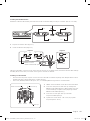
The electrical diagram is attach backside of range.
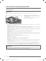
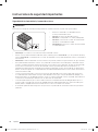
Customer-Assurance Information
To resolve questions and installation issues, contact your Dacor dealer or the Dacor Customer Assurance Team.
Before calling, have the range's model/serial numbers available. (See the range's data label: Located on the
bottom left side of the control panel.)
Dacor Customer Assurance:
1-833-353-5483(USA)
Monday - Friday 8:00 AM - 8:00 PM EST
1-844-509-4659(Canada)
Monday - Friday 8:00 AM - 8:00 PM EST
Website: www.dacor.com Customer
INSTALL_DOP48M86D_DG68-01454A-00_EN+MES+CFR.indb 3INSTALL_DOP48M86D_DG68-01454A-00_EN+MES+CFR.indb 3 2022-08-05 오후 5:00:132022-08-05 오후 5:00:13

English4
Important Safety Instructions
READ ALL INSTRUCTIONS BEFORE USING THIS APPLIANCE
• To avoid property damage/personal injury/death, follow the directions in this manual.
• Electrical and gas equipment with moving parts can be dangerous. The Important safety instructions in
this manual are intended to minimize the risk of property damage, personal injury, and death. Read these
instructions.
• Keep this manual in a handy place for reference.
Symbols In This Manual
Follow these warning icons and symbols explicitly to prevent property damage and personal injury.
WARNING
Hazards or unsafe practices that may result in severe personal injury or death.
CAUTION
Hazards or unsafe practices that may result in electric shock, personal injury, or property damage.
NOTE
Useful tips and instructions.
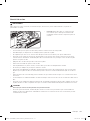
About Anti-Tip Device
WARNING
All ranges can tip and cause personal injury and death. Install and check the
anti- tip bracket per the instructions and template supplied with the bracket.
• After installing the anti-tip device (see Installing the Anti-Tip Device), verify proper installation by carefully
tipping the range forward. The anti-tip device should keep the range safely in place.
• When the range is put back in place after maintenance, be sure to re-engage the anti-tip device.
• To avoid personal/property damage, do not step/sit/lean on the range.
California Proposition 65 Warning
WARNING
Cancer and Reproductive Harm - www.P65Warnings.ca.gov.
Commonwealth of Massachusetts
This product must be installed by a licensed plumber or gas tter qualied or licensed by the State of
Massachusetts. When using ball-type gas shut-off valves, you must use the T-handle type. Multiple exible gas
lines must not be connected in series.
INSTALL_DOP48M86D_DG68-01454A-00_EN+MES+CFR.indb 4INSTALL_DOP48M86D_DG68-01454A-00_EN+MES+CFR.indb 4 2022-08-05 오후 5:00:132022-08-05 오후 5:00:13

English 5
Installation-Related Safety Instructions
This section consists of general and specic safety instructions surrounding the range's installation.
WARNING
Read these instructions thoroughly to reduce risk of property damage, re, personal injury, and death, and to
ensure proper installation.
General Safety
• Do not touch the range during or immediately after cooking.
• Know where and how to shut off/on the range's gas-supply valve.
• Use only dry pot holders.
• Do not let children sit/stand on the range or play with any of its parts. Do not leave children unattended
near the range when it is in use.
• Remove all packaging before operating the range, and properly and immediately dispose of the packaging.
• Keep all packaging away from children.
• Do not keep objects of interest to children on or around the range.
• Do not operate the range if it is damaged or malfunctioning, or is missing parts.
• Do not use oven cleaners/liners anywhere on the oven.
• Do not heat sealed food containers.
• Do not strike the oven glass.
• When disposing of the range, cut off the power cord, and remove the door.
• Shut off the gas, and unplug the range before service/maintenance.
• Cook meat to an internal temperature of 160 °F (71 °C) and poultry to 180 °F (82 °C).
• Air curtains or hoods that blow on the gas range shall be used only if the hood and range are designed and
tested per the Standard for Domestic Gas Ranges, ANSI Z21.1 • CSA1.1, and listed by an independent testing
lab for combination use.
• Never use the range as a space heater.
Fire Safety
• Do not store/place/use combustible items (e.g., paper, plastic, fabrics, gasoline) near the range.
• Do not wear loose-tting or hanging garments while using the range.
• Do not let pot holders or other ammable material touch a heating element. Do not use a towel or other
bulky cloth as a pot holder.
• Do not douse a grease re with water but turn off the burner, and smother the re with a tight- tting lid, or
use a multi-purpose, dry-chemical, or foam extinguisher.
• For oven res, keep the door closed, and press OFF. Do not open the door until the re goes out. If needed,
• use a multipurpose, dry-chemical, or foam extinguisher.
• Do not heat sealed containers; pressure may burst the container and cause injury.
INSTALL_DOP48M86D_DG68-01454A-00_EN+MES+CFR.indb 5INSTALL_DOP48M86D_DG68-01454A-00_EN+MES+CFR.indb 5 2022-08-05 오후 5:00:132022-08-05 오후 5:00:13

English6
Important safety instructions
WARNING
Read these instructions thoroughly to reduce risk of property damage, re, personal injury, and death, and to
ensure proper installation.
Gas Safety
If you smell gas:
• do not use the range, and close the gas valve.
• do not light a match, candle, or cigarette.
• do not turn on any gas or electric appliances.
• do not plug in a power cord or touch an electrical switch.
• do not use any phone in your building.
• evacuate the building.
• immediately call your gas supplier from a neighbor’s phone; follow the supplier’s directions.
• if you cannot reach your gas supplier, call the re department.
Checking For Gas Leaks
Leak-test the range per manufacturer directions. Do not use a ame to check for leaks. With a brush, spread
a soap-and-water solution around the area in question. If there is a gas leak, small bubbles will appear in the
solution. If unsure, call for professional help.
Electrical and Grounding Safety
• Do not remove the ground prong.
• Do not use an adapter or extension cord.
• Do not use a damaged plug, cord, or loose power outlet, and do not alter the plug, cord, or outlet.
• Do not put a fuse in a neutral or ground circuit.
• Use a dedicated 240 Vac, 60 Hz, 50 Amp breaker for the 48" Range and a 40 Amp breaker for the 36" Range.
A time-delay fuse or circuit breaker should be used. Plug only the range into this circuit.
• Do not connect the ground wire to plastic plumbing/gas lines, or hot water pipes.
• The range must be grounded. Grounding lowers the risk of electric shock by giving the current a safe path. If
unsure that your outlet is properly grounded, have a licensed electrician check it.
• The range has a grounded, 4-prong, plug that must be inserted in a grounded, 4-prong outlet that meets all
local ordinances. If codes allow a separate ground wire, a qualied electrician should determine its path.
• Electrical service to the range must conform to local codes, or in their absence, to the National Electrical
code/NFPA No. 70 – Latest Revision (for the U.S.) or the Canadian Electrical Code CSA C22.1 or Latest
Revisions.
• The owner shall ensure the range receives the proper electrical service.
INSTALL_DOP48M86D_DG68-01454A-00_EN+MES+CFR.indb 6INSTALL_DOP48M86D_DG68-01454A-00_EN+MES+CFR.indb 6 2022-08-05 오후 5:00:132022-08-05 오후 5:00:13

English 7
This section consists of general and specic safety instructions surrounding the range's installation.
WARNING
Read these instructions thoroughly to reduce risk of property damage, re, personal injury, and death, and to
ensure proper installation.
Installation Safety
• The range should be installed/grounded/serviced by a qualied installer as instructed in this manual.
• Do not service/alter/replace the range or any part of it unless as instructed in this manual. All other service
should be done by a qualied technician.
• Remove all tape and packing material.
• Use only new, exible connectors when installing the range.
• Ensure the anti-tip device is properly installed (Pg. 20).
• Due to the size and weight of the range, have two or more people move the range.
• After unpacking the product, remove all accessories, taking care with heavy pieces.
• Verify that no parts came loose during shipping.
• Ensure the range is correctly installed/adjusted by a qualied service technician or installer for the type
of gas (natural or LP) you will use. For the range to use LP gas, the installer must replace all surface burner
orices with the provided LP orice set, and reverse the GPR adapter. These adjustments must be made
per manufacturer instructions and local regulations. The qualied agency performing this work shall be
responsible for the gas conversion.
• Installation of this range must conform with local codes or, in their absence , with the National Fuel Gas Code,
ANSI Z223.1/NFPA.54, latest edition. In Canada, installation must conform with the current Natural Gas and
Propane Installation Code, CAN/CGA-B149.1, or the current Propane Installation Code, CAN/ CGA-B149.2, and
with local codes where applicable. This range has been design-certied by UL according to ANSI Z21.1/CSA
1.1, latest edition.
Location Safety
• Install the range indoors away from weather/water/strong drafts.
• If the range is near a window, do not hang paper blinds or long curtains that could be blown over/onto the
range.
• The range must be installed within easy reach of a grounded, 4-prong outlet.
• Wall and cabinet coverings around the range must withstand heat up to 194 °F (90 °C).
• Select a level, sturdy oor that can support the range’s weight (48": 564 lbs.). Synthetic ooring (e.g.,
linoleum) must withstand 180°F (82°C) without shrinking, warping, or discoloring. The range must be
separated from carpeting by a sheet of ¼" plywood or similar insulator.
• The range needs sufcient space all around the chassis for its vents to properly exhaust heat and fumes,
thus ensuring safe operation.
• Avoid cabinet storage above the range; otherwise, allow at least 30 in. (76.2 cm) from cooking surface to
cabinet bottom; or install a range hood that projects outward at least 5 in. (12.7 cm) beyond the cabinetry.
INSTALL_DOP48M86D_DG68-01454A-00_EN+MES+CFR.indb 7INSTALL_DOP48M86D_DG68-01454A-00_EN+MES+CFR.indb 7 2022-08-05 오후 5:00:132022-08-05 오후 5:00:13

English8
Important safety instructions
This section consists of general and specic safety instructions surrounding the range's installation.
WARNING
Read these instructions thoroughly to reduce risk of property damage, re, personal injury, and death, and to
ensure proper installation.
Cooktop Safety.
• Turn all burners off if not using the range.
• Do not line the grates or any part of the cooktop with foil.
• Do not leave burners unattended on medium or high settings.
• Before igniting, ensure burners and caps are properly seated.
• Use LITE (ame symbol) to ignite a burner. If the burner does not stay lit, turn the knob OFF, and wait
5 minutes for the gas to dissipate, then retry.
• When setting a burner to simmer, turn the knob slowly; ensure the burner stays lit.
• Place only cookware on the cooktop.
• The cooktop is designed to cook with a wok or wok-ring attachment.
• Food should only be cooked under an active ventilation hood.
• Before removing cookware, turn off the burner, and remove food/cookware when done cooking.
• Burners should be off and all surfaces cool before removing grates and burner parts. After cleaning the
burner head, dry it completely before re-assembly.
• Assemble the dual-burner spreader so its spark mark is next to the electrode.
• Do not pour water or other liquids into the cooktop.
• Select cookware that is designed for cooktops and that covers the grate. Burner ames should stay fully
under the cookware.
• Do not use cookware that is much larger than the grate.
• Turn cookware handles away from active burners and the cooktop front edge.
• Heat frying-oil slowly, and watch as it heats. When frying at high heat, stand at a safe distance, and monitor
the oil constantly. If combining fats/oils, mix them together before heating.
• Use a deep-fry thermometer if possible to avoid heating the oil beyond its smoke point.
• Fry with minimal oil. Thaw food fully before frying; do not fry icy or overly cold food. Let oil/fat cool to
room temperature before moving the cookware.
• To avoid delayed-eruptive boiling, let oil/fat stand at least 20 seconds after turning off the burner to
stabilize the temperature.
INSTALL_DOP48M86D_DG68-01454A-00_EN+MES+CFR.indb 8INSTALL_DOP48M86D_DG68-01454A-00_EN+MES+CFR.indb 8 2022-08-05 오후 5:00:142022-08-05 오후 5:00:14

English 9
This section consists of general and specic safety instructions surrounding the range's installation.
WARNING
Read these instructions thoroughly to reduce risk of property damage, re, personal injury, and death, and to
ensure proper installation.
Oven Safety
• Do not use the oven for non-cooking purposes such as drying clothes or storage. Use the oven for cooking
purposes only.
• Ensure the oven racks are placed on the same level on each side.
• Do not spray water on the oven glass while the oven is on or just after you turn it off.
• Do not clean the door gasket.
• Do not use cover/line any part of the oven with aluminium foil or like material.
• When using the oven, stand to one side when opening the door.
• Keep the oven free from grease buildup.
• Ensure the oven is completely cool before adjusting the oven racks.
• Do not leave plastic items in the oven.
• To avoid damaging the burner control knobs or oven control, always bake/broil with the oven door closed.
• Do not put meat too close to the broil element; trim excess fat before cooking meat.
• Use cooking bags as directed by the bag manufacturer.
• Do not use abrasive cleaners or metal scrapers to clean the oven-door glass.
• Do not try to operate the oven during a power failure.
• If power fails, turn the oven off. If the oven is not turned off and power returns, the oven may begin to
operate again. Unattended food could catch re or spoil.
Self-Cleaning Safety
• During self-cleaning, the oven operates at about 800 °F (427 °C). Do not touch any surfaces of the range
during a self-cleaning cycle, and keep children away from the oven.
• Before operating the self-clean cycle, wipe excess food residue from the oven. (Excess grease may ignite,
causing smoke damage.
• Before self-cleaning, remove all racks, cookware, and utensils from the oven. Only porcelain- coated oven
racks may be left in the oven.
• Stand aside when opening the oven door after self-cleaning.
• If the self-cleaning cycle malfunctions, turn off the oven and circuit breaker, and contact a qualied service
technician.
• Fumes released during self-cleaning can be harmful/fatal to pet birds. Move birds to a distant, well-
ventilated room.
• Do not use commercial oven cleaner or protective coating on the oven interior/exterior.
INSTALL_DOP48M86D_DG68-01454A-00_EN+MES+CFR.indb 9INSTALL_DOP48M86D_DG68-01454A-00_EN+MES+CFR.indb 9 2022-08-05 오후 5:00:142022-08-05 오후 5:00:14

English10
Product Specications
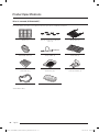
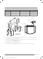
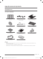
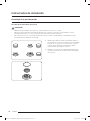
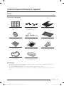
What Is Included (DOP48M86D**)
The range comes with brass and porcelain burner caps to suit customer preference.
Grates (3) Burner heads (6) and Burner
caps (7) Glide racks (2)
Convection lter (3) Temp. Probe (2) Wire rack (1)
Small rack (1)*) Steam tray (2)* Anti-tip bracket (1)
WOK ring (1) Half steam tray (2)*
*Steam ovens only
INSTALL_DOP48M86D_DG68-01454A-00_EN+MES+CFR.indb 10INSTALL_DOP48M86D_DG68-01454A-00_EN+MES+CFR.indb 10 2022-08-05 오후 5:00:162022-08-05 오후 5:00:16

English 11
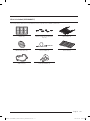
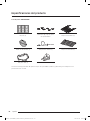
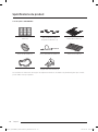
What Is Included (DOP36M86D**)
The range comes with brass and porcelain burner caps to suit customer preference.
Grates (3) Burner heads (6) and Burner
caps (7) Glide racks (2)
Convection lter (2) Temp. Probe (1) Wire rack (1)
WOK ring (1) Anti-tip bracket (1)
INSTALL_DOP48M86D_DG68-01454A-00_EN+MES+CFR.indb 11INSTALL_DOP48M86D_DG68-01454A-00_EN+MES+CFR.indb 11 2022-08-05 오후 5:00:172022-08-05 오후 5:00:17

Product Specications
English12
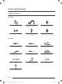
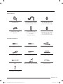
Needed Tools and Parts
Parts Needed
Gas line shut-off valve Flexible metal appliance
connector ¹/₂ in (ID) x 5 ft
Flare union adapter
³/₄ in (NPT) x ¹/₂ in (ID)
135-degree elbow (optional) Lag bolt or 1/2-in (OD)
sleeve anchor
Flare union adapter
1/2 in (NPT x 1/2 in (ID)
Tools Needed
Flat-blade screwdriver Phillips screwdriver Open-end or adjustable wrench
Pipe wrench (2) Nut driver Pencil and ruler
Level Pipe joint compound Utility knife
Soapy water solution
INSTALL_DOP48M86D_DG68-01454A-00_EN+MES+CFR.indb 12INSTALL_DOP48M86D_DG68-01454A-00_EN+MES+CFR.indb 12 2022-08-05 오후 5:00:182022-08-05 오후 5:00:18

English 13
Installation Requirements
Pre-Installation Checklist
1. Before installing the range, read this manual thoroughly.
2. Plan for a location where the range will not be subject to strong drafts.
3. Remove packaging, grate boxes, regulator with literature, and literature package from the range, verify that
all items are present before beginning the installation.
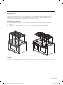
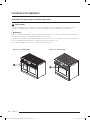
General Requirements
Clearances and Dimensions
• For over-the-range (OTR) over gas stove, follow the local gas code.
• For safe operation, provide adequate space between the range and combustible surfaces. Location of the
electrical outlet and gas piping may be adjusted to meet the dimensions and clearances in this manual.
• The range may be installed ush to the rear wall. A non-combustible material must be installed on the rear
wall between the range and hood. It is not necessary to install non- combustible material directly behind the
range. Openings in the wall behind the range or in the oor below must be sealed.
• Canada only: A free-standing range shall be installed at least 4.7 in. (12 cm) from all adjacent surfaces.
CAUTION
The range complies with the maximum allowable wood-cabinet temperature of 194 °F (90 °C). Ensure the
adjacent wall covering, countertops, and cabinets can withstand such heat to avoid discoloration, delamination, or
melting.
Minimum Dimensions
WARNING
Regarding overhead cabinets, a hood should be installed that projects at least 5" (12.7 cm) beyond the cabinetry
face to dissipate heat in those cabinets. The hood must consist of sheet metal at least .0122" thick. Install the
hood with at least 1/4" clearance between it and the bottom of the combustible material or metal cabinet. The
hood must be at least as wide as the range and centered over it. Clearance between the cook surface and hood
bottom must be at least 24". (For above-range cooking appliances, follow that appliance's installation criteria.)
• 30" (76.2 cm) minimum clearance between the cook surface and bottom of an unprotected wood/ metal
cabinet; or if no 30" (76.2 cm) min. clearance, 24" (61 cm) min. when the bottom of the wood/metal cabinet
is protected by at least .25" (.64 cm) ame-retardant millboard covered with at least No. 28 MSG sheet steel,
.015" (.038 cm) stainless steel, .024" (.061 cm) aluminum, or .02" (.051 cm) copper.
• 18 in. (45.7 cm) minimum between the countertop and adjacent cabinet bottom.
INSTALL_DOP48M86D_DG68-01454A-00_EN+MES+CFR.indb 13INSTALL_DOP48M86D_DG68-01454A-00_EN+MES+CFR.indb 13 2022-08-05 오후 5:00:182022-08-05 오후 5:00:18

Installation Requirements
English14
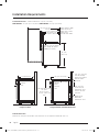
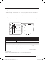
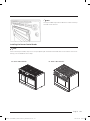
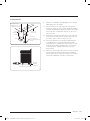
Product Dimensions — Product tolerances: ±1/16” (±1.6 mm)
DOP36M86D**: 35 7/8” (91.1 cm) wide ; DOP48M86D**: 47 7/8” (121.6cm)
Front of open door
Front of handle
Front of bull nose
Front panel
Rear of oven door
48" (121.9 cm)
28 1/8" (71.4 cm)
27 1/2" (69.9 cm)
26" (66.0 cm)
23 15/16" (60.8 cm)
15/16" (2.4 cm) top of
trim to top of grates
(cooking surface)
36 1/8"
(91.8 cm)
Range Installed
Range Installed with Downdraft Vent
29 7/8" (75.9 cm)***
Countertop*
Countertop height:
36 3/16"
(91.9 cm) min.
37 1/2" (95.3 cm)
max.
3/8" min. (1.0 cm)
at countertop
overhang needed
behind cutout
3/8" (1.0 cm)
space behind
downdraft vent
chassis to clear
stiffener
MR35-ER or
MR48-ER
downdraft vent
Stiffener
Back of
control
panel
Cabinet
face
Cabinet
face
24" (61.0 cm)
Cabinet Dimensions
Maintain all max/min dimensions and clearances in the diagrams below for safe use.
INSTALL_DOP48M86D_DG68-01454A-00_EN+MES+CFR.indb 14INSTALL_DOP48M86D_DG68-01454A-00_EN+MES+CFR.indb 14 2022-08-05 오후 5:00:182022-08-05 오후 5:00:18

English 15
CUTOUT DIMENSIONS
Range Model A B C
DOP36M86D** 42” (106.7 cm)*;
36” (91.4 cm)**
36” (91.4 cm)**;
36 1/8” (91.7 cm)*** 33 1/2” (84.8 cm)
DOP48M86D** 54” (137.2 cm)*;
48” (121.9 cm)**
48” (121.9 cm)**;
48 1/8” (122.2 cm)*** 43 1/2” (110.5 cm)
*Recommended, **Minimum, ***Maximum
B
C
Note 2
Backsplash
3" (7.6 cm)
Cutout with Optional Downdraft Vent
(Top View)
A
B
Note 2
18" (45.7 cm)4.5
13" (33.0 cm)
max.5
30" (76.2 cm)
max.1
37 1/2"
(95.3 cm)
max.
Non-combustible
Surface along back wall
recommended
Suggested
location of
utilities3
Standard Cutout
with Range Hoof
10" (25.4 cm)
min. to
combustible
side walls
above range
(both sides)
3/8" (1.0 cm) min.
at countertop
overhang
10" (25.4 cm) mín.
to combustible side
walls above range
(both sides)
Non-combustible rear
wall (recommended)
Grate
level
Top of
nished
counter
1. Vertical from range grate level to combustible overhead surface; if installing an overhead hood, see hood
specications for minimum required clearances.
2. Cabinet/countertop depth is at the customer's discretion, but cabinet face must not protrude beyond the rear
of the front panel. (See Product Dimensions, Pg. 14)
3. Consult local codes for exact location requirements.
4. Vertical from grate level to combustible surface.
5. Does not apply to cabinets more than a horizontal distance of 10" (25.4 cm) from the range edge.
INSTALL_DOP48M86D_DG68-01454A-00_EN+MES+CFR.indb 15INSTALL_DOP48M86D_DG68-01454A-00_EN+MES+CFR.indb 15 2022-08-05 오후 5:00:192022-08-05 오후 5:00:19

Installation Requirements
English16
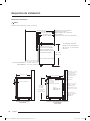
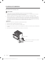
Location Requirements
DOP48M86D** (rear)
Gas Inlet
6 5/8"
(16.8 cm)
8 1/8"
(20.6 cm)
5 1/2"
(13.9 cm)
26 5/8"
(67.6 cm)
E - Electrical wiring
access hole in bottom
Shown with
electrical access
cover removed
DOP36M86D** (rear)
11 3/16"
(28.4 cm)
24 1/4"
(61.6 cm)
6 5 /8"
(16.8 cm)
8 7/8"
(22.5 cm)
Shown with electrical
access cover removed
Gas Inlet
1. Measurement with appliance legs adjusted to lowest
height.
2. The hole size for the electrical wiring may be
increased to 1 1/8” (2.9 cm) by removing the conduit
bracket in the bottom of the range electrical box.
INSTALL_DOP48M86D_DG68-01454A-00_EN+MES+CFR.indb 16INSTALL_DOP48M86D_DG68-01454A-00_EN+MES+CFR.indb 16 2022-08-05 오후 5:00:192022-08-05 오후 5:00:19

English 17
Gas and Electrical Service
• See below for the recommended location of the gas inlet and electrical junction box/receptacle. Existing
utilities may be used if they are compatible with this range. Check local building codes for allowed gasvalve
locations.
• An external manual shut-off valve must be installed between the gas inlet and range so the range's gas
supply can be turned on/off. Installation must allow access to the gas shut-off valve when the unit is
installed and access to the remote circuit-breaker panel/fuse box without moving the range.
• The gas-supply piping and shut-off valve, and the electrical junction box/receptacle must be located so as
not to interfere with the range when it is installed.
• The junction box and gas-shut off valve must be located so the range can be pulled out for service without
being disconnected.
Model D E F G
DOP36M86D** 8 7/8" (22.5 cm) 6 5/8" (16.8 cm) 11 3/16" (28.4 cm) 24 1/4" (61.6 cm)
DOP48M86D** 5 1/2" (13.9 cm) 6 5/8" (16.8 cm) 8 1/8" (20.6 cm) 26 5/8" (67.6 cm)
G
E
D
F
Recommended
position for
Gas stub
Recommended
position for
electrical outlet
INSTALL_DOP48M86D_DG68-01454A-00_EN+MES+CFR.indb 17INSTALL_DOP48M86D_DG68-01454A-00_EN+MES+CFR.indb 17 2022-08-05 오후 5:00:192022-08-05 오후 5:00:19

Installation Requirements
English18
Gas Requirements
Provide Adequate Gas Supply
This oven's installation must conform to local codes or, in their absence, with the National Fuel Gas Code, ANSI
Z223.1/NFPA 54.
This range's cooktop is designed to operate at a manifold pressure of 5 in. (13 cm) of water column for natural
gas/natural gas at high altitude (NG-H) or 10 in. (25.4 cm) of water column for LP (propane)/LP at high altitude
(LP-H).
Verify that the oven is right for the provided gas service.
When verifying regulator function, inlet pressure must be at least 1 in. (2.5 cm) greater than the operating
(manifold) pressure as given.
GAS SUPPLY PRESSURE REQUIREMENTS*
Gas Type Minimum Manifold Pressure Minimum Gas Supply Pressure**
Natural Gas 5” Water Column 6” Water Column
LP (propane) Gas 10” Water Column 11” Water Column
*The gas supply pressure for testing the regulator setting shall be at least 1" water column (249 Pa) above the
specied manifold pressure; **Maximum gas supply pressure for all models: 1/2 psi.
NOTE
• The pressure regulator at the inlet of the cooktop manifold must stay in the supply line whether or not
natural or LP gas is used.
• Use only the range's regulator, which must be installed in the gas line that runs from the cooktop gas inlet to
the gas shut-off valve.
• An external manual shut-off valve must be installed between the gas inlet and range for turning on/off gas
to the appliance.
• Ensure the connectors are installed by a qualied installer.
• To avoid leaks and personal injury, never install used connectors on a new product. Use only new, exible
connectors.
Special Gas Requirements (gas models sold in Massachusetts)
WARNING
• Gas leaks may occur in your system, creating a hazardous condition. Such leaks may not be detected
by smell alone; thus, gas suppliers recommend installing a UL-approved gas detector per manufacturer
specications.
• The range must be installed by a plumber or gas tter certied by the State of Massachusetts.
• A T-handle manual gas valve MUST be installed in the gas-supply line to your range.
• If using a exible gas connector, multiple lines must not be connected in series.
INSTALL_DOP48M86D_DG68-01454A-00_EN+MES+CFR.indb 18INSTALL_DOP48M86D_DG68-01454A-00_EN+MES+CFR.indb 18 2022-08-05 오후 5:00:192022-08-05 오후 5:00:19

English 19
Electrical Requirements
Follow these directions to reduce risk of property damage, personal injury, or death.
WARNING
The owner shall ensure that the electrical service meets requirements and that the electrical outlet is installed by
a licensed electrician.
All Ranges
• Do not use an extension cord or adapter plug with this range.
• This range must be plugged in to a properly grounded outlet. (Check with a qualied electrician if you doubt
that the outlet is properly grounded.)
• Do not alter the power plug. Have a proper outlet installed by a qualied electrician.
• All wiring/grounding must comply with local codes or, in their absence, with the National Electrical Code,
ANSI/NFPA No. 70 – Latest Revision (US), or the Canadian Electrical Code CSA C22.1 – Latest Revisions and
local codes.
• The wiring diagram is on the back of the range.
• A dedicated circuit breaker is required.
• Use this chart to identify the minimum recommended dedicated circuit protection.
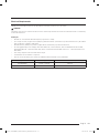
Range Model KW Rating (240 V) Recommended Circuit Size (Dedicated)
DOP36M86D** 7.3 KW - 9.6 KW 40 Amp
DOP48M86D** 9.7 KW - 12.0 KW 50 Amp
INSTALL_DOP48M86D_DG68-01454A-00_EN+MES+CFR.indb 19INSTALL_DOP48M86D_DG68-01454A-00_EN+MES+CFR.indb 19 2022-08-05 오후 5:00:192022-08-05 오후 5:00:19

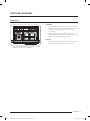
English20
Installation Instructions
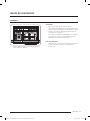
Preparing for Installation
WARNING
• If the gas or electric service provided does not meet the product specications, do not proceed with the
installation. Call the dealer, the gas supplier or a licensed electrician.
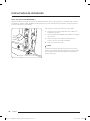
• Before installing the range, you must locate and secure the anti-tip bracket to the oor.
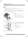
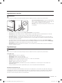
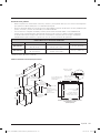
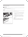
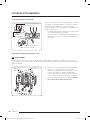
Unpacking the Range
Unpack the parts box and verify that all required components have been provided. If any item is missing or
damaged, please contact your dealer immediately. Do not install a damaged or incomplete appliance.
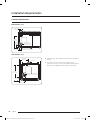
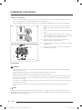
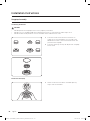
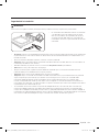
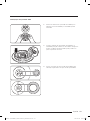
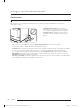
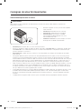
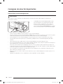
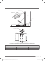
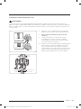
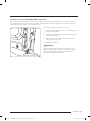
Installing the Anti-tip Bracket and Foot
There are two ways to mount the anti-tip bracket: Floor mounting (preferred), and wall mounting (Pg. 22). Use
this method if oor mounting is unsuitable; however, if the range's front panel is over 26 1/2” (67.3 cm) from the
back wall or if the oor is too thick, oor mounting must be used.
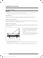
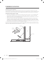
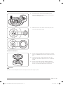
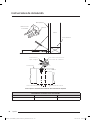
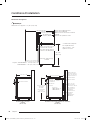
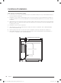
Floor-Mounting the Anti-Tip Bracket
To perform as designed, the anti-tip bracket must attach to the concrete slab or wood sub-oor below any upper
ooring (including cement board). Do not attach the anti-tip bracket directly to oor coverings such as ceramic/
asphalt tile or linoleum.
Floor covering
Sub-oor Screws attached
through ooring
into sub-oor
Anchors shown
(concrete sub-oor only)
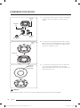
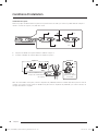
• Four plastic anchors are provided with three sizes (4
each) of #8 or #12 Phillips head screws for attaching
the anti-tip bracket to the oor. Use both anchors
and four of the screws to attach the bracket to a
concrete sub-oor. Do not use anchors on a wood
sub-oor.
• Determine the location of the range center line and
front panel for the range’s nal position based on the
Product Dimensions (Pg. 14) and the actual cabinet/
cutout dimensions used for the installation.
• Determine the required position of the anti-tip bracket, based on the diagram below. Mark the 4 mounting-
hole locations on the oor with a pencil.
• Determine the screw size. The minimum full thread depth (portion of screw threaded into wood/slab) is 3/8”
(1 cm) for wood and 5/8” (1.6 cm) for concrete. (See SCREW SIZE table, below, for correct screw sizes.)
INSTALL_DOP48M86D_DG68-01454A-00_EN+MES+CFR.indb 20INSTALL_DOP48M86D_DG68-01454A-00_EN+MES+CFR.indb 20 2022-08-05 오후 5:00:192022-08-05 오후 5:00:19
La page est en cours de chargement...
La page est en cours de chargement...
La page est en cours de chargement...
La page est en cours de chargement...
La page est en cours de chargement...
La page est en cours de chargement...
La page est en cours de chargement...
La page est en cours de chargement...
La page est en cours de chargement...
La page est en cours de chargement...
La page est en cours de chargement...
La page est en cours de chargement...
La page est en cours de chargement...
La page est en cours de chargement...
La page est en cours de chargement...
La page est en cours de chargement...
La page est en cours de chargement...
La page est en cours de chargement...
La page est en cours de chargement...
La page est en cours de chargement...
La page est en cours de chargement...
La page est en cours de chargement...
La page est en cours de chargement...
La page est en cours de chargement...
La page est en cours de chargement...
La page est en cours de chargement...
La page est en cours de chargement...
La page est en cours de chargement...
La page est en cours de chargement...
La page est en cours de chargement...
La page est en cours de chargement...
La page est en cours de chargement...
La page est en cours de chargement...
La page est en cours de chargement...
La page est en cours de chargement...
La page est en cours de chargement...
La page est en cours de chargement...
La page est en cours de chargement...
La page est en cours de chargement...
La page est en cours de chargement...
La page est en cours de chargement...
La page est en cours de chargement...
La page est en cours de chargement...
La page est en cours de chargement...
La page est en cours de chargement...
La page est en cours de chargement...
La page est en cours de chargement...
La page est en cours de chargement...
La page est en cours de chargement...
La page est en cours de chargement...
La page est en cours de chargement...
La page est en cours de chargement...
La page est en cours de chargement...
La page est en cours de chargement...
La page est en cours de chargement...
La page est en cours de chargement...
La page est en cours de chargement...
La page est en cours de chargement...
La page est en cours de chargement...
La page est en cours de chargement...
La page est en cours de chargement...
La page est en cours de chargement...
La page est en cours de chargement...
La page est en cours de chargement...
La page est en cours de chargement...
La page est en cours de chargement...
La page est en cours de chargement...
La page est en cours de chargement...
La page est en cours de chargement...
La page est en cours de chargement...
La page est en cours de chargement...
La page est en cours de chargement...
La page est en cours de chargement...
La page est en cours de chargement...
La page est en cours de chargement...
La page est en cours de chargement...
La page est en cours de chargement...
La page est en cours de chargement...
La page est en cours de chargement...
La page est en cours de chargement...
La page est en cours de chargement...
La page est en cours de chargement...
La page est en cours de chargement...
La page est en cours de chargement...
La page est en cours de chargement...
La page est en cours de chargement...
La page est en cours de chargement...
La page est en cours de chargement...
La page est en cours de chargement...
La page est en cours de chargement...
La page est en cours de chargement...
La page est en cours de chargement...
La page est en cours de chargement...
La page est en cours de chargement...
La page est en cours de chargement...
La page est en cours de chargement...
La page est en cours de chargement...
La page est en cours de chargement...
La page est en cours de chargement...
La page est en cours de chargement...
La page est en cours de chargement...
La page est en cours de chargement...
La page est en cours de chargement...
La page est en cours de chargement...
La page est en cours de chargement...
La page est en cours de chargement...
La page est en cours de chargement...
La page est en cours de chargement...
La page est en cours de chargement...
La page est en cours de chargement...
La page est en cours de chargement...
La page est en cours de chargement...
La page est en cours de chargement...
La page est en cours de chargement...
La page est en cours de chargement...
La page est en cours de chargement...
La page est en cours de chargement...
La page est en cours de chargement...
La page est en cours de chargement...
La page est en cours de chargement...
La page est en cours de chargement...
La page est en cours de chargement...
La page est en cours de chargement...
La page est en cours de chargement...
La page est en cours de chargement...
La page est en cours de chargement...
La page est en cours de chargement...
La page est en cours de chargement...
La page est en cours de chargement...
La page est en cours de chargement...
La page est en cours de chargement...
La page est en cours de chargement...
La page est en cours de chargement...
La page est en cours de chargement...
La page est en cours de chargement...
La page est en cours de chargement...
La page est en cours de chargement...
La page est en cours de chargement...
La page est en cours de chargement...
La page est en cours de chargement...
La page est en cours de chargement...
La page est en cours de chargement...
La page est en cours de chargement...
La page est en cours de chargement...
La page est en cours de chargement...
La page est en cours de chargement...
La page est en cours de chargement...
La page est en cours de chargement...
-
 1
1
-
 2
2
-
 3
3
-
 4
4
-
 5
5
-
 6
6
-
 7
7
-
 8
8
-
 9
9
-
 10
10
-
 11
11
-
 12
12
-
 13
13
-
 14
14
-
 15
15
-
 16
16
-
 17
17
-
 18
18
-
 19
19
-
 20
20
-
 21
21
-
 22
22
-
 23
23
-
 24
24
-
 25
25
-
 26
26
-
 27
27
-
 28
28
-
 29
29
-
 30
30
-
 31
31
-
 32
32
-
 33
33
-
 34
34
-
 35
35
-
 36
36
-
 37
37
-
 38
38
-
 39
39
-
 40
40
-
 41
41
-
 42
42
-
 43
43
-
 44
44
-
 45
45
-
 46
46
-
 47
47
-
 48
48
-
 49
49
-
 50
50
-
 51
51
-
 52
52
-
 53
53
-
 54
54
-
 55
55
-
 56
56
-
 57
57
-
 58
58
-
 59
59
-
 60
60
-
 61
61
-
 62
62
-
 63
63
-
 64
64
-
 65
65
-
 66
66
-
 67
67
-
 68
68
-
 69
69
-
 70
70
-
 71
71
-
 72
72
-
 73
73
-
 74
74
-
 75
75
-
 76
76
-
 77
77
-
 78
78
-
 79
79
-
 80
80
-
 81
81
-
 82
82
-
 83
83
-
 84
84
-
 85
85
-
 86
86
-
 87
87
-
 88
88
-
 89
89
-
 90
90
-
 91
91
-
 92
92
-
 93
93
-
 94
94
-
 95
95
-
 96
96
-
 97
97
-
 98
98
-
 99
99
-
 100
100
-
 101
101
-
 102
102
-
 103
103
-
 104
104
-
 105
105
-
 106
106
-
 107
107
-
 108
108
-
 109
109
-
 110
110
-
 111
111
-
 112
112
-
 113
113
-
 114
114
-
 115
115
-
 116
116
-
 117
117
-
 118
118
-
 119
119
-
 120
120
-
 121
121
-
 122
122
-
 123
123
-
 124
124
-
 125
125
-
 126
126
-
 127
127
-
 128
128
-
 129
129
-
 130
130
-
 131
131
-
 132
132
-
 133
133
-
 134
134
-
 135
135
-
 136
136
-
 137
137
-
 138
138
-
 139
139
-
 140
140
-
 141
141
-
 142
142
-
 143
143
-
 144
144
-
 145
145
-
 146
146
-
 147
147
-
 148
148
-
 149
149
-
 150
150
-
 151
151
-
 152
152
-
 153
153
-
 154
154
-
 155
155
-
 156
156
-
 157
157
-
 158
158
-
 159
159
-
 160
160
-
 161
161
-
 162
162
-
 163
163
-
 164
164
-
 165
165
-
 166
166
-
 167
167
-
 168
168


Samsung DOP36M86DLS Guide d'installation
- Catégorie
- Cuisinières
- Taper
- Guide d'installation
dans d''autres langues
Documents connexes
-
Samsung DTG30M954FM Manuel utilisateur
-
-
-
Samsung NY63T8751SG Guide d'installation
-
-
-
-
-
-
Samsung NX58M6650WG Manuel utilisateur
Autres documents
-
Dacor DOP30T940DS Mode d'emploi
-
Yes DOP36C86DLS/DA Guide d'installation
-
Yes DOB30P977SS Manuel utilisateur
-
-
-
-
LG STUDIO CBGS3628S Guide d'installation
-
LG CBGS3028S Guide d'installation
-
BUT Bibliothéque 3 étagères LOUISON Pin massif ciré Mode d'emploi