Samsung NK30N7000US/AA Manuel utilisateur
- Taper
- Manuel utilisateur

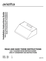
Range Hood
Hotte de la cuisine
Campana de cocina
Installation Instructions Guide
Guide d’instructions d’installation
Guía de Instrucciones para Instalación
NK30N7000US / NK36N7000US / NK30N7000UG / NK36N7000UG
LIB0139973A

2 English
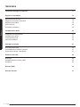
Important Safety Instructions 3
Installation Requirements 5
Electrical Requirements 5
Venting Requirements 5
Venting Methods 5
Tools and Parts 6
Dimensions and Clearances 6
Installation 7
Prepare Location 7
Installing the Range Hood 8
Connect Vent System 9
Electrical Connection 10
Complete Installation 11
Range Hood Use 11
Range Hood Description 11
Range Hood Controls 11
Connectivity Cooktop / Hood Range 12
Range Hood Care 13
Cleaning 13
Replacing a LED Lamp 13
Accesories 13
Warranty (USA) 14
Warranty (Canada) 15
Table of Contents
Table of Contents

English 3
APPROVED FOR RESIDENTIAL APPLIANCES
FOR RESIDENTIAL USE ONLY
READ AND SAVE THESE INSTRUCTIONS
PLEASE READ ENTIRE INSTALLATION GUIDE BEFORE PROCEEDING.
INSTALLATION MUST COMPLY WITH ALL LOCAL CODES.
IMPORTANT: Save these Instructions for the Local Electrical
Inspector’s use.
INSTALLER: Please leave these Instructions with this unit for
the owner.
OWNER: Please retain these instructions for future
reference.
Symbols used in this manual
WARNING
Hazards or unsafe practices that may result in severe personal injury or
death.
CAUTION
Hazards or unsafe practices that may result in electric shock, personal
injury, or property damage.
NOTE
Useful tips and instructions
These warning icons and symbols are here to prevent injury to you and
others.
Please follow them explicitly. After reading this section, keep it in a safe
place for future reference.
WARNING
Turn off power circuit at service panel and lock
out panel before wiring this appliance.
Requirement 120 VAC, 60 Hz. 15 or 20 A Branch Circuit
State of California Proposition 65 warning (US only)
WARNING
This product contains chemicals known to the State of California to cause
cancer and birth defects or other reproductive harm.
1. FCC Notice
CAUTION
FCC CAUTION: Any changes or modications not expressly approved
by the party responsible for compliance could void the user’s authority to
operate the equipment.
This device complies with Part 15 of FCC Rules. Operation is Subject to
following two conditions:
1) This device may not cause harmful interference, and
2) This device must accept any interference received including
interference that cause undesired operation.
For products sold in the US and Canadian markets, only channels 1~11
are available. You cannot select any other channels.
Important Safety Instructions
Important Safety Instructions
FCC STATEMENT:
This equipment has been tested and found to comply within the limits
for a Class B digital device, pursuant to part 15 of the FCC Rules. These
limits are designed to provide reasonable protection against harmful
interference in a residential installation.
This equipment generates, uses, and can radiate radio frequency energy
and, if not installed and used in accordance with the instructions, may
cause harmful interference to radio communications.
However, there is no guarantee that interference will not occur in a
particular installation. If this equipment does cause harmful interference
to radio or television reception, which can be determined by turning
the equipment off and on, the user is encouraged to try to correct the
interference by one or more of the following measures:
• Reorienting or relocating the receiving antenna
• Increasing the separation between the equipment and receiver
• Connecting the equipment to an outlet that is on a different circuit than
the radio or TV.
• Consulting the dealer or an experienced radio/TV technician for help.
FCC RADIATION EXPOSURE STATEMENT:
This equipment complies with FCC radiation exposure limits set forth for
an uncontrolled environment. This equipment should be installed and
operated so there is at least 8 inches (20 cm) between the radiator and
your body. This device and its antenna(s) must not be co-located or
operated in conjunction with any other antenna or transmitter.
2. IC Notice
The term “IC” before the radio certication number only signies
that Industry Canada technical specications were met. Operation is
subject to the following two conditions: (1) this device may not cause
interference, and (2) this device must accept any interference, including
interference that may cause undesired operation of the device.
This Class B digital apparatus complies with Canadian ICES-003. For
products sold in the US and Canadian markets, only channels 1~11 are
available. You cannot select any other channels.
IC RADIATION EXPOSURE STATEMENT:
This equipment complies with IC RSS-102 radiation exposure limits set
forth for an uncontrolled environment. This equipment should be installed
and operated so there is at least 8 inches (20 cm) between the radiator
and your body. This device and its antenna(s) must not be co-located or
operated in conjunction with any other antenna or transmitter.

4 English
Important Safety Instructions
WARNING
TO REDUCE THE RISK OF FIRE, ELECTRIC SHOCK, OR INJURY TO
PERSONS, OBSERVE THE FOLLOWING PRECAUTIONS:
■ Use this unit only in the manner intended by the manufacturer. If you
have questions, contact the manufacturer.
■ Before servicing or cleaning the unit, switch the power off at the
service panel and lock the service panel to prevent power from being
switched on accidentally. If the service panel cannot be locked,
securely fasten a prominent warning device, such as a tag to the
service panel.
■ Installation work and electrical wiring must be done by qualied
person(s) in accordance with all applicable codes and standards,
including re-rated construction.
■ Sufcient air is needed for proper combustion and exhausting of
gases through the ue (chimney) of fuel burning equipment to
prevent backdrafting. Follow the heating equipment manufacturer’s
guideline and safety standards such as those published by the
National Fire Protection Association (NFPA), the American Society
for Heating, Refrigeration and Air Conditioning Engineers (ASHRAE),
and the local code authorities.
■ When cutting or drilling into the wall or ceiling; do not damage
electrical wiring and other hidden utilities.
■ Ducted fans must always be vented outdoors.
CAUTION
For general ventilating use only. Do not use to exhaust hazardous or
explosive materials and vapors.
CAUTION
To reduce the risk of re and to properly exhaust air, be sure to duct air
outside - do not vent exhaust air into spaces within walls or ceilings, attics
or into crawl spaces, or garages.
WARNING
TO REDUCE THE RISK OF FIRE, USE ONLY METAL DUCTWORK.
WARNING
TO REDUCE THE RISK OF A RANGE TOP GREASE FIRE:
■ Never leave surface units unattended at high settings. Boilovers
cause smoking and greasy spillovers that may ignite. Heat oils slowly
on low or medium settings.
■ Always turn the hood ON when cooking at high heat or when ambeing
food (i.e. Crepes Suzette, Cherries Jubilee, Peppercorn Beef Flambé).
■ Clean ventilating fans frequently. Grease should not be allowed to
accumulate on the fan or lter.
■ Use proper pan sizes. Always use cookware appropriate for the size
of the surface element.
WARNING
TO REDUCE THE RISK OF INJURY TO PERSONS IN THE EVENT OF
A RANGE TOP GREASE FIRE, OBSERVE THE FOLLOWING
PRECAUTIONS:
a
■ SMOTHER FLAMES with a close tting lid, cookie sheet, or metal
tray, then turn off the burner. BE CAREFUL TO PREVENT BURNS.
If the ames do not go out immediately, EVACUATE AND CALL THE
FIRE DEPARTMENT.
■ NEVER PICK UP A FLAMING PAN - you may get burned.
■ DO NOT USE WATER, including wet dishcloths or towels -
a violent steam explosion can result.
■ Use an extinguisher ONLY if:
- You know you have a class ABC extinguisher, and you already know
how to operate it.
– The re is small and contained in the area where it started.
– The re department is being called.
– You can ght the re with your back to an exit.
a
Based on “Kitchen Fire Safety Tips” published by NFPA.
WARNING
To reduce the risk of re or electrical shock, do not use this fan with any
solid-state speed control device.
WARNING
Do not let children near this appliance. Do not let children play with this
appliance.
Keep all packaging materials out of children’s reach. Properly dispose the
packaging materials after this appliance is unpacked.
Important Safety Instructions
Read and save these instructions

English 5
Electrical Requirements
IMPORTANT
Observe all governing codes and ordinances.
It is the customer’s responsibility:
To contact a qualied electrical installer.
To assure that the electrical installation is adequate and in
conformance with National Electrical Code, ANSI/NFPA 70
— latest edition*, or CSA Standards C22.1-94, Canadian
Electrical Code, Part 1 and C22.2 No.0-M91 - latest edition** and all local
codes and ordinances.
If codes permit and a separate ground wire is used, it is recommended
that a qualied electrician determine that the ground path is adequate.
A copy of the above code standards can be obtained from:
National Fire Protection Association
1 Batterymarch Park
Quincy, MA 02169-7471
CSA International
8501 East Pleasant Valley Road
Cleveland, OH 44131-5575
■ A 120 volt, 60 Hz., AC only, 15-amp, fused electrical circuit is required.
■ If the house has aluminum wiring, follow the procedure below:
1. Connect a section of solid copper wire to the pigtail leads.
2. Connect the aluminum wiring to the added section of
copper wire using special connectors and/or tools designed
and UL listed for joining copper to aluminum.
■ Follow the electrical connector manufacturer’s recommended
procedure. Aluminum/copper connection must conform with local
codes and industry accepted wiring practices.
■ Wire sizes and connections must conform with the rating of the
appliance as specied on the model/serial rating plate. The model
serial plate is located behind the lter on the rear wall of the range hood.
■ Wire sizes must conform to the requirements of the National Electrical
Code, ANSI/NFPA 70 (latest edition), or CSA Standards C22. 1-94,
Canadian Electrical Code, Part 1 and C22.2 No. 0-M91 (latest edition)
and all local codes and ordinances.
Venting Requirements (ducted models only)
• Vent system must terminate outdoors.
• Do not terminate the vent system in an attic or other enclosed area.
• Do not use a 4” (10.2 cm) laundry-type wall cap.
• Use metal vent only. Rigid metal vent is recommended.
Plastic or metal foil vent is not recommended.
• The length of the vent system and the number of elbows should
be kept to a minimum to provide efcient performance.
For the most efcient and quiet operation:
• Use no more than three 90° elbows.
• Make sure there is a minimum of 24” (61 cm) of straight vent
between the elbows if more than 1 elbow is used.
• Do not install 2 elbows together.
• Use clamps to seal all joints in the vent system.
• The vent system must have a damper. If the roof or wall cap
has a damper, do not use the damper supplied with the range
hood.
• Use caulking to seal the exterior wall or roof opening around the cap.
• The size of the vent should be uniform.
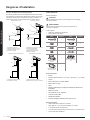
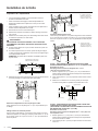
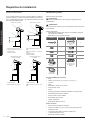
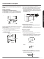
Venting Methods
To use the hood’s top outlet to vent your hood, a 6” (15.2 cm) round vent
system is required. To use the hood’s rear outlet, a 3
1
⁄4” x 10” (8.25 x 25.4
cm) rectangular vent system is required. Neither of these vent systems
are included and must be purchased separately.
NOTE
Flexible vent is not recommended. Flexible vent creates back pressure
and air turbulence that greatly reduce performance. The vent system can
terminate either through the roof or wall. To vent through a wall, a 90°
elbow is needed.
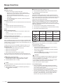
Mounting Height
Select a mounting height between a minimum of 24” (61 cm) for an
electric cooking surface, a minimum of 27” (68.6 cm) for a gas cooking
surface, and a suggested maximum of 36” (91.4 cm) above the range to
the bottom of the hood.
Rear discharge
A 90° elbow may be installed immediately above the hood.
For Non-Vented (recirculating) Installations
If it is not possible to vent cooking fumes and vapors to the outside,
the hood can be used in the non-vented (recirculating) version, tting a
charcoal lter and a plastic grid. Fumes and vapors are recycled through
the a recirulation grid.
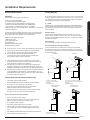
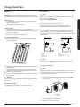
Roof Venting Wall Venting
A
C
B
D
A
C
B
D
A. 6” (15.2 cm) round vent
B. 6” (15.2 cm) round transition
C. Roof cap
D. Installation height
A. 6” (15.2 cm) round vent + 90º elbow
B. 3
1
⁄4” x 10” (8.25 x 25.4 cm) rectangular vent
C. Wall cap
D. Installation height
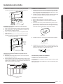
Recirculating through
the cabinet’s top
Recirculating through
the cabinet’s front
A
B
A
B
A. Recirculation grid
B. 6” (15.2 cm) round vent
A. Recirculation grid
B. 6” (15.2 cm) round vent + 90º elbow
Installation Requirements
Installation Requirements

6 English
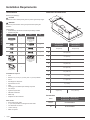
Tools and Parts
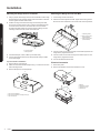
Removing the packaging
CAUTION
Remove the carton carefully. Wear gloves to protect against sharp edges.
WARNING
Remove the protective lm covering the product before putting into
operation.
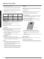
Parts supplied
• Hood assembly with blower and LED lamps already installed.
• Hardware bag with:
Part Qty Part Qty
5x45 mm
4
5.4x75 mm screws
(for 10x60 mm wall
anchors)
4
4.5x13 mm
4
10 x 60 mm
4
3.5x9.5 mm
2
Torx 10 adapter
1
4.2x8 mm
7
Torx 20 adapter
1
6” (15.2 cm) round
transition
1
Rectangular transition
3
1
⁄4” x 10” (8.3 x 25.4
cm) with back draft
dampers
1
Rear blower
mounting bracket
1
Tools/Materials required
• Level
• Drill with 1¼” (3.2 cm),
1
⁄8” (3.2 mm), and
1
⁄16” (4,8 mm) drill bits
• Pencil
• Wire stripper or utility knife
• Tape measure or ruler
• Pliers
• Caulking gun and weatherproof caulking compound
• Vent clamps
• Jigsaw or keyhole saw
• Flat-blade screwdriver
• Metal snips
• Phillips & Torx 20 screwdrive
r
Parts needed
• Home power supply cable
• ½” (12.7 mm) UL listed or CSA approved strain relief
• 3 UL listed wire connectors
• 1 wall or roof cap
• Metal vent system
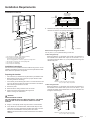
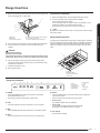
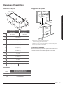
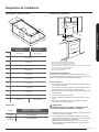
Dimensions and Clearances
A
B
L
K
H
E
G
F
C
I
D
J
NK30N7000US
NK30N7000UG
NK36N7000US
NK36N7000UG
A 30″ (76 cm) 36″ (91.2 cm)
B 19
6
⁄8″ (50 cm)
C 9
3
⁄4″ (25 cm)
D 13
13
⁄16″ (35 cm)
E 12″ (30.5 cm)
F 2
3
⁄16″ (5.5 cm)
G 7
1
⁄4″ (18.4 cm)
H 1
3
⁄16″ (3 cm)
I 1
1
⁄16″ (2.6 cm)
J
5
⁄8″ (1.6 cm)
K 1
10
⁄16″ (4 cm)
L 3″ (7.6 cm) 5
3
⁄4″ (14.6 cm)
Accessories
Model
NK30N7000US - NK36N7000US
NK30N7000UG - NK36N7000UG
Charcoal
Filter Kit
NK-AR050FNB/AA
Recirculation
Kit
NK-AF030FNB/AA
Installation Requirements
Installation Requirements

English 7
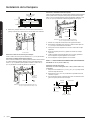
Installation
Installation Clearances
C
B
A
E
D
A. 18” (45.7 cm) min. clearance - upper cabinet to countertop
B. 24” (61.0 cm) min. for electric cooking surfaces
27” (68.6 cm) min. for gas cooking surfaces
36” (91.4 cm) suggested max. - bottom of range hood to cooking surface
C. 30” (76.2 cm) or 36” (91.4 cm) min. cabinet opening width
D. 12” (30.5 cm) min. cabinet depth
E. 36” (91.4 cm) base cabinet height
Installation Instructions
We recommend that a qualied technician install the range hood. It is the
installer’s responsibility to ensure the range hood complies with the instal-
lation clearances specied for the product.
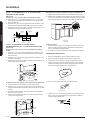
Preparing the location
• We recommend you install the vent system before you install the hood.
• Before making cutouts, make sure there is proper clearance within
the ceiling or wall for vent ttings.
• If the cabinet you are attaching the hood to is not mounted on the wall
yet, it may be easier to attach the cutout to the bottom of the cabinet
before mounting the cabinet on the wall.
1. Disconnect power.
2. Determine which venting method to use: roof or wall.
3. Select a at surface for assembling the range hood.
Place a covering over that surface.
WARNING
EXCESSIVE WEIGHT HAZARD
USE TWO OR MORE PEOPLE TO MOVE AND INSTALL THE RANGE
HOOD. FAILURE TO DO SO CAN RESULT IN BACK OR OTHER
INJURIES.
4. Using 2 or more people, lift the range hood onto a covered surface.
5. If the cabinet has a recessed bottom, add wood ller strips on each
side to ll in the space. Install screws to attach ller strips in the loca-
tions shown in the illustration at the top of the next column.
NOTE: All the screw locations must be measured from the cabinet’s
centerline.
Wood ller strips
(recessed cabinet
bottoms only)
Cabinet
bottom
Wall
3” (7.6 cm)
CL
30”model: 13
13
⁄16” (35 cm)
36”model: 16
6
⁄8” (42,5 cm)
30”model: 13
13
⁄16” (35 cm)
36”model: 16
6
⁄8” (42,5 cm)
3” (7.6 cm)
6. Determine and clearly mark a vertical centerline on the wall and
cabinet in the area the vent opening will be made.
A
A. Centerline
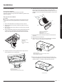
Determine the wiring hole location
Cut only one 1
1
⁄4” (3.2 cm) diameter wiring access hole.
To wire through the top:
Mark a line Distance “A” (See below) from the left of the centerline on
the underside of the cabinet. Mark a point on this line that is 1
9
⁄16” (4
cm) from the back wall. Drill a 1¼” (3.2 cm) diameter hole through the
cabinet at this point.
A
Centerline
1
9
⁄16” (4 cm)
from wall, not
cabinet frame
Distance A. 12” (30.5 cm) for 30” (76.2 cm) models
12¼” (31.1 cm) for 36” (91.4 cm) models
To wire through the wall:
Mark a line Distance “A” (See below) from the left of the centerline on
the underside of the cabinet. Mark a point on this line that is 1” (2.54
cm) below the bottom of the cabinet. Drill a 1¼” (3.2 cm) diameter hole
through the wall at this point.
Centerline
A
1” (2.5 cm)
Distance A. 12” (30.5 cm) for 30” (76.2 cm) models
12¼” (31.1 cm) for 36” (91.4 cm) models
Installation Requirements

8 English
STYLE 1 - CUT OPENINGS FOR 3¼” X 10” (8.3 CM X 25.4 CM)
RECTANGULAR VENT SYSTEM
Wall venting
To make a 4” x 10½” (10.2 cm x 26.7 cm) rectangle in the wall:
1. Draw one line 2
3
⁄4” (7.0 cm) and a second line 6
3
⁄4” (17.1 cm) below
the underside of the cabinet. Extend these lines through the center-
line on the back wall.
2. Draw lines 5¼” (13.3 cm) to the right and left of the centerline on the
wall. Make sure these lines intersect with the lines you drew in Step 1.
3. With the lines you drew as a guide, use a saber or keyhole saw to cut
a rectangular opening in the wall for the vent.
Centerline
Cabinet
front
2
3
⁄4” (7.0 cm)
6
3
⁄4” (17.1 cm)
5
1
⁄4”
(13.3 cm)
5
1
⁄4”
(13.3 cm)
STYLE 2 - CUT OPENINGS FOR TOP VENT OUTLET
(FROM RECTANGULAR TO 6” (15.2 CM) ROUND VENT SYSTEM)
Roof venting
To make a 6½” x 8½” (16.5 cm x 21.6 cm) rectangle in the cabinet
bottom:
1. Draw a line ½” (1.3 cm) from the back wall on the centerline of the
underside of the cabinet, and then draw another line 6½” (16.5 cm)
from the rst line.
2. Draw lines 4¼” (10.8 cm) to the right and left of the centerline on the
underside of the cabinet.
3. With the lines you drew as a guide, use a saber or keyhole saw to cut
a rectangular opening for the vent.
4
1
⁄4”
(10.8 cm)
)
*
1
⁄2”
(1.3 cm)
4
1
⁄4”
(10.8 cm)
From wall, not cabinet frame
7
10
⁄16” (19.4 cm)
1
9
⁄16” (4 cm)
Ø 1”
(2.54 cm)
6
1
⁄2”
(16.5 cm)
To make a circular vent opening on the underside of the cabinet top:
1. Draw a centerline on the underside of the top of the cabinet.
2. Draw a line 3
7
⁄8” (9.7 cm) from the back wall on the underside of the
top of the cabinet. Make sure the line intersects with the line you drew
in Step 1.
3. Where the two lines intersect, use a compass or a circle template to
draw a 6¼” (15.2 cm) circle.
4. With the circle you drew as a guide, use a saber or keyhole saw to
cut the circular vent opening.
*From wall, not
cabinet frame
Cabinet
cutouts
*3
7
⁄8”
(9.7 cm)
Circular vent opening
6
1
⁄4”
15.2 cm
Non-Vented (recirculating) Installation through the Soft/Cabinet
1. Measure and mark the centerline of the cabinet to the soft above.
2. Measure from the bottom of the cabinet to the centerline of the where
the vent will come through the soft. Mark the location and use a saber
saw or keyhole saw to cut a 5¾” (14.6 cm) hole for the vent cover.
B
A
A.Vent cover
B. Centerline
Install vent system
1. Install the vent through the vent opening in the cabinet or wall. Com-
plete the venting system according to the selected venting method.
See the “Venting Requirements” section.
2. Use caulking to seal the exterior wall or roof opening around the cap.
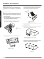
Installing the Range Hood
1. Remove the bafe lters. See the “Range Hood Care” section.
2. Remove the foam shipping pad from behind the blower motor.
3. Lift the range hood up under the cabinet and determine it’s nal
location by centering it beneath the cabinet. Mark on the underside
of cabinet the location of the 4 keyhole mounting slots on the range
hood. Set the range hood aside on a covered surface.
A
A. Keyhole slot
4. Use a
1
⁄8” (3 mm) drill bit and drill 4 pilot holes as shown.
A
A. Drill pilot hole
5. Install the 4 - 4.5 x 13 mm mounting screws in the pilot holes. Leave
about
1
⁄4” (6.4 mm) space between the screw heads and cabinet to
slide the range hood into place.
1
⁄4” (6.4 mm)
Installation
Installation

English 9
Installation
Connect Vent System
Vent connector installation
The range hood is factory set for use the top vent outlet.
Determine whether the range hood will be installed using either a top or
rear vent connection.
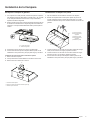
Rear vent connector installation
NOTE
For rear venting, the blower motor position must be changed. You will
need the rear motor mounting bracket that is included with the range
hood.
1. Remove the bafe lters. See the “Range hood care” section.
2. Place the range hood on its back. Fit the vent system over the ex-
haust outlet.
3. Disconnect the blower motor electrical connector from the electrical
box connector.
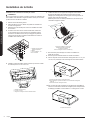
4. Using a T20® adapter, remove the 4 screws holding the blower motor
in place. Push up on the blower motor to disengage the tabs from
range hood cavity back. Remove the blower motor and set it aside.
C
B
A
A. Range hood canopy
(inside top)
B. Blower motor
C. Blower motor mounting
screws
5. Install the rear blower mounting bracket into the range hood and
secure it with the (4) 4.2 x 8 mm screws.
A
B
B
C
A. Range hood canopy (inside back)
B. 4.2 x 8 mm screws (4)
C. Rear blower motor mounting bracket assembly
6. Install the blower motor onto the rear motor mounting bracket (included
with the range hood). Engage the motor mounting tabs with the
keyhole slots in the rear mounting bracket and push down to secure.
Install the 4 screws removed previously and tighten to secure motor
bracket.
A
B
C
D
A. Rear motor mounting bracket
B. Motor mounting tabs (2)
C. Blower motor
D. Blower motor mounting screws (4)
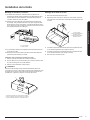
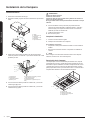
7. Reconnect blower motor electrical connector to the electrical box
connector.
8. Remove the rear vent knockout.
9. Attach the 3
1
⁄4” x 10” (8.3 cm x 25.4 cm) rectangular vent damper
using 3 - 4.2x8 mm vent transition mounting screws.
C
B
A
A. Rear vent knockout
B. Rear rectangular transition knockout mounting screws (3)
C. Rear rectangular vent transition
10. Remove one of the round knockouts from the top or back of the
range hood (depending on your wiring location) for the wiring strain
relief and install a
1
⁄2” UL listed or CSA approved strain relief.
A
A. Round knockout
Installation

10 English
Installation
Mounting the Range Hood on a Cabinet
1. Using 2 people, lift the range hood into it’s nal location. Feed enough
electrical wire through the strain relief to make connections in the termi-
nal box. Tighten the strain relief screws.
2. Position the range hood so that the large end of the keyhole slots
are over the mounting screws. Then, push the hood toward the wall
so that the screws are in the neck of the slots. The hood should
be against the wall. Tighten the mounting screws, making sure the
mounting screws are in the narrow neck of the slots.
B
A
A. 4- mounting screws
B. Security screws
3. Check that damper, if used, rotates up and down freely.
4. Connect the ventwork to the hood. Seal joints with clamps to make
secure and airtight.
Top vent transition installation
1. Remove the top vent knockout.
2. Attach the round vent transition damper using 2 - 3.5x9.5 mm vent tran-
sition mounting screws.
3. Remove the tape from the damper ap.
A
B
C
A. Top round vent transition
B. Top round vent transition mounting screws (2)
C. Top vent knockout
Installation
Mounting the Range Hood on the Wall
1. Fix the wiring conduit of the hood.
2. Slide the hood back against the wall. Tighten the mounting screws.
Be sure the screw heads are in the narrow neck of the keyhole slot.
A
C
B
B
A. Mounting Screws
B. Upper security screws
(Wall Installation)
C. Lower security screws
(Wall Installation)
3. Insert 2 screws into the upper security screw locations (see B in the
image above). Tighten the screws.
4. Insert 2 screws into the lower security screw location (see C in the
image above). Tighten the screws.
5. Connect the ductwork to the hood.
Electrical Connection
1. Disconnect power.
2. Remove the bracket, and then the terminal box cover.
A
B
D
C
B
A. Bracket
B. Terminal box screws
C. Terminal box cover
D. Terminal box

English 11
Range Hood Use
Range Hood Use
3. Remove the knockout in the terminal box cover, and then install a UL
listed or CSA approved
1
⁄2” strain relief.
E
F
A
B
C
D
A. White wires
B. Black wires
C. UL listed wire connectors
D. Green (or bare) and yellow-green ground wire
E. Home power supply cable
F. UL listed or CSA approved ½” strain relief
4. Use UL listed wire connectors to connect the black wires (B) together.
5. Use UL listed wire connectors to connect the white wires (A)
together.
WARNING
Electrical Shock Hazard
Electrically ground blower.
Connect the ground wire to the green and yellow ground wire in the
terminal box. Failure to do so can result in death or electrical shock.
6. Connect the green (or bare) ground wire from the home power
supply to the yellow-green ground wire (D) in the terminal box using
UL listed wire connectors.
7. Install the terminal box cover.
8. Reconnect the power.
Complete the Installation
1. Replace the bafe lters. See the “Range Hood Care” section.
2. Check the operation of the range hood fan and lights.
See the “Range Hood Use” section.
If the range hood does not operate, check to see whether a circuit
breaker has tripped or a household fuse has blown.
Disconnect the power and check the wiring connections.
NOTE
To get the most efcient use from your new range hood, read the “Range
Hood Care” section.
Range Hood Description
The range hood is designed to remove smoke, cooking vapors, and odors
from the cooktop area. For best results, start the hood before cooking and
allow it to operate several minutes after cooking to clear all smoke and
odors from the kitchen. The hood controls are located on the front of the
hood.
D
B
C
A
A. Bafe lter
B. Bafe lter handle
C. Blower and light controls
D. LED lamps
Range Hood Controls
A B C D E GF H I J
A. Power
B. Low Speed
C. Medium Speed
D. High Speed
E. Boost Speed
F. Timer Display
G. Timer
H. Light
I. Auto
Connectivity
J. Bluetooth
A. POWER
• Press the POWER button and the hood will turn on at default
speed (Default Speed : Low).
• Press again and the hood will return to sleep mode.
B. LOW
• Press the LOW button and the hood will turn on at Low speed.
C. MED
• Press the MED button and the hood will turn on at Medium speed.
D. HIGH
• Press the HIGH button and the hood will turn on at High speed.
E. BOOST
• Press the BOOST button and the hood will increase to Maximum
speed for 10 minutes.
• After 10 minutes, the hood will slow to High speed.
• Normal mode
High & Boost CFM is the same (390CFM).
• Power mode
High mode is 390 CFM and Boost mode is 600 CFM.
See Performance (CFM) Conversion on page 12.
F. Timer Display
• Shows the timer settings.

12 English
G. Timer
Setting the timer ON
• Press the Timer button to set the working time.
• Each time you press the Timer, you add 10 minutes to the
displayed time, up to a maximum of 99 minutes. The hood will
stay on for the amount of time you have set.
• After the Timer counts down to zero, the Timer LED light will
start to blink.
• The Timer LED will blink for 5 seconds, and then the hood will
turn off automatically.
Setting the timer OFF
• Press the Timer button for 3 seconds and the Timer function will turn off.
H. Light
• Press the Light button and the lamps will turn on.
• Press the Light button again and the lamps will turn off.
Sound
Muting / Unmuting the hood.
• Press and hold the Light button for 3 seconds to turn off the hood
sounds.
• Press and hold again to turn on the sounds.
Cooktop and Range Hood Connectivity
This appliance has a feature which allows you to pair compatible Samsung
cooktops and your hood via Bluetooth.
After you enable this function and pair your hood and a compatible cooktop,
the hood fan will automatically come on at Low speed when you turn on a
cooktop element. The hood fan will also shut off automatically when you
turn off the cooktop elements.
In addition, after the hood and compatible cooktop are paired, you can
download the Smart Things app to a mobile device, and then use the
Smart Things app to:
• Monitor and control the On/Off status of the hood.
• Monitor and control the fan speed.
• Monitor and control the lights.
• Set the hood shut-off timer with the time-up alarm.
For more information about downloading the Smart Things app to your
mobile device and using it to control your hood, visit: www.samsung.com.
J.
Bluetooth connection (pairing)
1. Press the Bluetooth button on hood. The pairing mode will be
activated and the indicator on the Bluetooth button will blink.
2. Press the Bluetooth button on cooktop.
NOTE
For a detailed description of the pairing method, see the user manual of a
compatible Samsung cooktop.
3. After the pairing proccess nishes, the Bluetooth light will stay lit
and
appears in the display.
Bluetooth disconnection (Pairing reset)
1. Press and hold the Bluetooth button on the hood for 3 seconds.
2. The Bluetooth connection disconnects.
I. Auto Connectivity
The Auto Connectivity function lets you quickly connect the hood via
Bluetooth with a compatible Samsung cooktop after the hood and cook-
top have been paired. To turn the function on, press the Auto Connectivity
button. To turn the function off and disconnect the hood and cooktop,
press the Auto Connectivity button again.
While the hood and cooktop are connected, the hood fan will automat-
ically come on at Low speed when you turn on a cooktop element. The
hood fan will also shut off automatically when you turn off the cooktop
elements. You will also be able to control the hood with the Smart Things
app as described above.
1. Press the Auto Connectivity button to activate the function.
2. The hood will turn on/off automatically in conjunction with the cooktop.
3. Press again to deactivate the function.
Image
Remote Control
by Smart Things
App
Auto
Connectivity
Hood
Function
X X O
O X O
O O O
NOTE
These functions are only available if you have installed a compatible
Samsung Bluetooth cooktop.
Performance (CFM) Conversion
• Press and hold the HIGH and BOOST button on the hood for 3
seconds to convert Blower performance.
• Normal mode:
appears in the display. The blower will operate
normally (Max 390 CFM).
• Power mode:
appears in the display. The blower will operate
at a more powerful level (Max 600 CFM).
CAUTION
We recommend that a qualied technician install the range hood to
ensure it is compatible with Power mode. DO NOT activate Power
mode if the installation is not compatible.
It is the installer’s responsibility to ensure the range hood complies
with the installation clearances specied for the product.
Power mode requires a custom air system.
The Custom Air System
• When using ventilation systems with greater than specied air
movement CFM, review local building codes as they may require
you to install a custom air system.
Consult a HVAC professional for specic requirements for you’re
area as CFM requirements can vary between locales.
• Consult a HVAC professional to select the correct CFM capacity
range hood for your application. The CFM capacity depends on
the range or cooktop BTU rating, size and location, size of the
kitchen and the range hood ductwork in the kitchen.
Range Hood Use
Range Hood Use

English 13
Range Hood Care
Cleaning
IMPORTANT: Clean the hood and grease lters frequently according to
the following instructions. Replace bafe lters before operating the hood.
Exterior surfaces:
• To avoid damage to the exterior surface, do not use steel wool or
soap-lled scouring pads.
• Always wipe dry to avoid water marks.
Cleaning method:
• Liquid detergent soap and water or all-purpose cleanser.
• Wipe with damp soft cloth or nonabrasive sponge, and then rinse with
clean water and wipe dry.
• Do not use cleaning agents containing bleach
Stainless steel bafe lter:
1. Remove the lter by pulling the spring release handle, and then
pulling down the lter.
A
A. Spring release handle
2. Wash the stainless steel bafe lter as needed in a dishwasher or hot
detergent solution.
3. To reinstall the lter, rst make sure the spring release handle is
toward the front. Insert the stainless steel lter into the upper track.
4. Push in the spring release handle.
5. Push up on the stainless steel lter, and then release the handle to
latch it into place.
WARNING
When removing the lter, please hold it with both hands to make sure it
does not fall.
Replacing the LED lamps
The LED lights are replaceable by a service technician only.
See the support contact information in the Warranty section.
Accessories
NOTE
When used in recirculation mode, To Reduce the Risk of Fire and Shock
use only conversion kit Models:
Recirculating kit: NK-AF030FNB/AA
Charcoal lter replacement: NK-AR050FNB/AA
Recirculating kit are not included with the hood.
They must be ordered from your supplier or Samsung service center.
Order the needed kit specifying your hood model and width size.
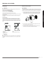
Recirculating kit
If it is not possible to vent cooking fumes and vapors to the outside, the
range hood can be used in the non-vented (recirculating) version, using a
charcoal lter. Recirculation Kit is available from the dealer or an authorized
parts distributor.
A
B
D
G
F
E
H
A
G
B
D
E
F
C
A. Ceiling
B. Vent cover
C. Soft
D. 6” (15.2 cm) vent
E. Range hood
F. Cabinet
G. Wall
H. 17” (43.2 cm) min.
vent cover height
NOTE
12” (30.5 cm) high cabinets without a soft may allow the 6” (15.2 cm)
vent and vent cover to be seen.
To replace charcoal lter:
NOTE
The maximum BTUs if you use carbon lter is 40 000. If you use the hood
with the carbon lters on and it does not decrease the BTUs the engine
can fail or generate an unsafe act.
1. Cover the grille that covers the blower motor with the charcoal lter
so that the slots on the lter correspond to the pins on the sides of
the motor grille.
C
B
A
A. Charcoal lter
B. Pins
C. Blower motor
2. Turn the charcoal lter clockwise to lock it.
3. Repeat steps 1-2 on the other lter.
Range Hood Care

warranty (USA)
SAMSUNG RANGE HOOD
Limited warranty to original purchaser
This SAMSUNG brand product, as supplied and distributed by
Samsung Electronics America, Inc. (SAMSUNG) and delivered
new, in the original carton to the original consumer purchaser, is
warranted by SAMSUNG against manufacturing defects in mate-
rials and workmanship for a limited warranty period of:
ONE (1) YEAR PARTS AND LABOR
This limited warranty begins on the original date of purchase,
and is valid only on products purchased and used in the United
States. To receive warranty service, the purchaser must contact
SAMSUNG for problem determination and service procedures.
Warranty service can only be performed by a SAMSUNG au-
thorized service center. The original dated bill of sale must be
presented upon request as proof of purchase to SAMSUNG or
SAMSUNG’s authorized service center.
SAMSUNG will repair or replace this product, at our option and
at no charge as stipulated herein, with new or reconditioned
parts or products if found to be defective during the limited
warranty period specied above. All replaced parts and prod-
ucts become the property of SAMSUNG and must be returned
to SAMSUNG. Replacement parts and products assume the
remaining original warranty, or ninety (90) days, whichever is
longer.
In-home service will be provided during the warranty labor
period subject to availability within the contiguous United States.
In-home service is not available in all areas. To receive in-home
service, the product must be unobstructed and accessible to
service personnel. If during in-home service repair can not be
completed, it may be necessary to remove, repair and return the
product.
This limited warranty covers manufacturing defects in materials
and workmanship encountered in normal, noncommercial use of
this product and shall not apply to the following, including, but
not limited to: damage which occurs in shipment; delivery and
installation; applications and uses for which this product was not
intended; altered product or serial numbers; cosmetic damage
or exterior nish; accidents, abuse, neglect, re, water, lightning
or other acts of nature; use of products, equipment, systems,
utilities, services, parts, supplies, accessories, applications,
installations, repairs, external wiring or connectors not supplied
or authorized by SAMSUNG which damage this product or result
in service problems; incorrect electrical line voltage, uctuations
and surges; customer adjustments and failure to follow operating
instructions, cleaning, maintenance and environmental instruc-
tions that are covered and prescribed in the instruction book;
problems caused by pest infestations, and overheating by user.
THERE ARE NO EXPRESS WARRANTIES OTHER THAN THOSE
LISTED AND DESCRIBED ABOVE, AND NO WARRANTIES
WHETHER EXPRESS OR IMPLIED, INCLUDING, BUT NOT
LIMITED TO, ANY IMPLIED WARRANTIES OF MERCHANT-
ABILITY OR FITNESS FOR A PARTICULAR PURPOSE, SHALL
APPLY AFTER THE EXPRESS WARRANTY PERIODS STATED
ABOVE, AND NO OTHER EXPRESS WARRANTY OR GUAR-
ANTY GIVEN BY ANY PERSON, FIRM OR CORPORATION
WITH RESPECT TO THIS PRODUCT SHALL BE BINDING ON
SAMSUNG. SAMSUNG SHALL NOT BE LIABLE FOR LOSS OF
REVENUE OR PROFITS, FAILURE TO REALIZE SAVINGS OR
OTHER BENEFITS, OR ANY OTHER SPECIAL, INCIDENTAL OR
CONSEQUENTIAL DAMAGES CAUSED BY THE USE, MISUSE
OR INABILITY TO USE THIS PRODUCT, REGARDLESS OF
THE LEGAL THEORY ON WHICH THE CLAIM IS BASED, AND
EVEN IF SAMSUNG HAS BEEN ADVISED OF THE POSSIBILITY
OF SUCH DAMAGES. NOR SHALL RECOVERY OF ANY KIND
AGAINST SAMSUNG BE GREATER IN AMOUNT THAN THE
PURCHASE PRICE OF THE PRODUCT SOLD BY SAMSUNG
AND CAUSING THE ALLEGED DAMAGE. WITHOUT LIMITING
THE FOREGOING, PURCHASER ASSUMES ALL RISK AND
LIABILITY FOR LOSS, DAMAGE OR INJURY TO PURCHASER
AND PURCHASER’S PROPERTY AND TO OTHERS AND THEIR
PROPERTY ARISING OUT OF THE USE, MISUSE OR INABILITY
TO USE THIS PRODUCT SOLD BY SAMSUNG NOT CAUSED
DIRECTLY BY THE NEGLIGENCE OF SAMSUNG. THIS LIMITED
WARRANTY SHALL NOT EXTEND TO ANYONE OTHER THAN
THE ORIGINAL PURCHASER OF THIS PRODUCT IS NON-
TRANSFERABLE AND STATES YOUR EXCLUSIVE REMEDY.
Some provinces or territories may or may not allow limitations on
how long an implied warranty lasts, or the exclusion or limitation
of incidental or consequential damages, so the above limitations
or exclusions may not apply to you. This warranty gives you
specic legal rights, and you may also have other rights which
vary from state to state.
To obtain warranty service, please contact SAMSUNG at:
1-800-SAMSUNG (726-7864) or
www.samsung.com/us/support

warranty (Canada)
SAMSUNG RANGE HOOD
Limited warranty to original purchaser
This SAMSUNG brand product, as supplied and distributed by
Samsung Electronics Canada, Inc. (SAMSUNG) and delivered
new, in the original carton to the original consumer purchaser, is
warranted by SAMSUNG against manufacturing defects in mate-
rials and workmanship for a limited warranty period of:
ONE (1) YEAR PARTS AND LABOR
This limited warranty begins on the original date of purchase,
and is valid only on products purchased and used in Canada. To
receive warranty service, the purchaser must contact SAMSUNG
for problem determination and service procedures. Warranty ser-
vice can only be performed by a SAMSUNG authorized service
center. The original dated bill of sale must be presented upon
request as proof of purchase to SAMSUNG or SAMSUNG’s
authorized service center.
SAMSUNG will repair or replace this product, at our option and
at no charge as stipulated herein, with new or reconditioned
parts or products if found to be defective during the limited
warranty period specied above. All replaced parts and prod-
ucts become the property of SAMSUNG and must be returned
to SAMSUNG. Replacement parts and products assume the
remaining original warranty, or ninety (90) days, whichever is
longer.
In-home service will be provided during the warranty labor
period subject to availability within the contiguous Canada.
In-home service is not available in all areas. To receive in-home
service, the product must be unobstructed and accessible to
service personnel. If during in-home service repair can not be
completed, it may be necessary to remove, repair and return the
product.
This limited warranty covers manufacturing defects in materials
and workmanship encountered in normal, noncommercial use of
this product and shall not apply to the following, including, but
not limited to: damage which occurs in shipment; delivery and
installation; applications and uses for which this product was not
intended; altered product or serial numbers; cosmetic damage
or exterior nish; accidents, abuse, neglect, re, water, lightning
or other acts of nature; use of products, equipment, systems,
utilities, services, parts, supplies, accessories, applications,
installations, repairs, external wiring or connectors not supplied
or authorized by SAMSUNG which damage this product or result
in service problems; incorrect electrical line voltage, uctuations
and surges; customer adjustments and failure to follow operating
instructions, cleaning, maintenance and environmental instruc-
tions that are covered and prescribed in the instruction book;
problems caused by pest infestations, and overheating by user.
SAMSUNG does not warrant uninterrupted or error-free opera-
tion of the product.
THERE ARE NO EXPRESS WARRANTIES OTHER THAN THOSE
LISTED AND DESCRIBED ABOVE, AND NO WARRANTIES
WHETHER EXPRESS OR IMPLIED, INCLUDING, BUT NOT
LIMITED TO, ANY IMPLIED WARRANTIES OF MERCHANT-
ABILITY OR FITNESS FOR A PARTICULAR PURPOSE, SHALL
APPLY AFTER THE EXPRESS WARRANTY PERIODS STATED
ABOVE, AND NO OTHER EXPRESS WARRANTY OR GUAR-
ANTY GIVEN BY ANY PERSON, FIRM OR CORPORATION
WITH RESPECT TO THIS PRODUCT SHALL BE BINDING ON
SAMSUNG. SAMSUNG SHALL NOT BE LIABLE FOR LOSS OF
REVENUE OR PROFITS, FAILURE TO REALIZE SAVINGS OR
OTHER BENEFITS, OR ANY OTHER SPECIAL, INCIDENTAL OR
CONSEQUENTIAL DAMAGES CAUSED BY THE USE, MISUSE
OR INABILITY TO USE THIS PRODUCT, REGARDLESS OF
THE LEGAL THEORY ON WHICH THE CLAIM IS BASED, AND
EVEN IF SAMSUNG HAS BEEN ADVISED OF THE POSSIBILITY
OF SUCH DAMAGES. NOR SHALL RECOVERY OF ANY KIND
AGAINST SAMSUNG BE GREATER IN AMOUNT THAN THE
PURCHASE PRICE OF THE PRODUCT SOLD BY SAMSUNG
AND CAUSING THE ALLEGED DAMAGE. WITHOUT LIMITING
THE FOREGOING, PURCHASER ASSUMES ALL RISK AND
LIABILITY FOR LOSS, DAMAGE OR INJURY TO PURCHASER
AND PURCHASER’S PROPERTY AND TO OTHERS AND THEIR
PROPERTY ARISING OUT OF THE USE, MISUSE OR INABILITY
TO USE THIS PRODUCT SOLD BY SAMSUNG NOT CAUSED
DIRECTLY BY THE NEGLIGENCE OF SAMSUNG. THIS LIMITED
WARRANTY SHALL NOT EXTEND TO ANYONE OTHER THAN
THE ORIGINAL PURCHASER OF THIS PRODUCT IS NON-
TRANSFERABLE AND STATES YOUR EXCLUSIVE REMEDY.
Some provinces or territories may or may not allow limitations on
how long an implied warranty lasts, or the exclusion or limitation
of incidental or consequential damages, so the above limitations
or exclusions may not apply to you. This warranty gives you
specic legal rights, and you may also have other rights which
vary from state to state.
To obtain warranty service, please contact SAMSUNG at:
1-800-SAMSUNG (726-7864) or
www.samsung.com/ca/support (English),
www.samsung.com/ca_fr/support (French)

16 Français
Importantes Consignes de Sécurité 17
Exigences d’Installation 19
Spécications Électriques 19
Exigences Concernant l’évacuation 19
Méthodes d’évacuation 19
Outils et Pièces 20
Dimensions et Espaces 20
Installation de la Hotte 22
Préparation de l’emplacement 22
Installation de la Hotte 23
Connexion Électrique 26
Achever l’installation 26
Utilisation de la Hotte 27
Description de la Hotte 26
Commandes de la Hotte de Cuisinière 27
Connectivity Cooktop / Hood Range 27
Entretien de la Hotte 29
Nettoyage 28
Remplacement de la Lampe à DEL 28
Accesoires 29
Garantie (USA) 30
Garantie (Canada) 31
Sommaire
Sommaire

Français 17
APPROUVÉ POUR LES APPAREILS DE TYPE RÉSIDENTIEL POUR
UNE UTILISATION RÉSIDENTIELLE SEULEMENT LISEZ CES
INSTRUCTIONS ET CONSERVEZ-LES
VEUILLEZ LIRE CES INSTRUCTIONS AU COMPLET AVANT DE
COMMENCER.
L’INSTALLATION DE L’APPAREIL DOIT RESPECTER TOUS LES
CODES EN VIGUEUR.
IMPORTANT:
INSTALLATEUR:
PROPRIÉTAIRE:
Conservez ces instructions an de pouvoir les
remettre à l’inspecteur-électricien de votre
région.
Veuillez laisser ces instructions avec l’appareil
pour le propriétaire.
Veuillez conserver ces instructions pour pouvoir
vous y référer plus tard.
Symboles utilisés dans ce manuel
AVERTISSEMENT
Dangers ou pratiques dangereuses qui peuvent entraîner des blessures
personnelles graves ou la mort.
ATTENTION
Dangers ou practiques dangereuses qui peuvent entraîner un choc
électrique, des blessures personnelles ou des dommages matériels.
REMARQUE
Des conseils et des instructions utiles
Ces icônes et ces symboles d’avertissement sont là pour prévenir des
blessures qui peuvent vous arriver aussi bien à vous qu’aux autres.
S’il vous plaît suivez-les de manière explicite. Après avoir lu cette section,
le conserver dans un endroit sure pour des références futures.
AVERTISSEMENT
Coupez l’alimentation du circuit dans le panneau électrique et verrouillez
le panneau avant de raccorder les ls de cet appareil.
Exigence 120 V c.a., 60 Hz circuit de dérivation de 15 V c.a., 20 Hz, de
15 ou 20 A.
Etat de Californie Proposition 65 avertissement (Etats-Unis
seulement)
AVERTISSEMENT
Ce produit contient des produits chimiques reconnus par l’Etat de
Californie comme pouvant provoquer des cancers et des malformations
congénitales ou autres problèmes de reproduction.
Avis de la FCC
ATTENTION
Mise en garde de la FCC: Tout changement ou modication qui n’est
pas expressément approuvés par la partie responsable de cet appareil
électrique (l’entreprise) pourrait annuler les droits des consommateurs à
utiliser l’équipement.
Cet appareil est conforme à la partie 15 des règles de la FCC. Le
fonctionnement est soumis à deux conditions suivantes :
1) Ce dispositif ne peut pas causer d’interférences néfastes, et
2) Cet appareil doit accepter toute interférence reçue, y compris les
interférences qui peuvent provoquer un mauvais fonctionnement.
Pour les produits vendus sur les marchés américains et canadiens, seuls
les canaux 1~11 sont disponibles. Vous ne pouvez pas sélectionnez
d’autres canaux.
Importantes Consignes de Sécurité
Importantes Consignes de Sécurité
DECLARATION DE LA FCC :
Cet équipement a été testé et jugé conforme aux limites pour un appareil
numérique de classe B, en vertu de la partie 15 des règles de la FCC.
Ces limites sont conçues pour fournir une protection raisonnable contre
les néfastes interférences dans une installation résidentielle.
Cet équipement génère, utilise et peut émettre de l’énergie de radio
fréquence et, si il n’est pas installé et utilisé conformément aux
instructions, il peut provoquer des interférences néfastes dans des
communications radio.
Cependant, il n’y a aucune garantie que l’interférence ne se produira
pas dans une installation particulière. Si cet équipement provoque des
interférences néfastes à la réception radio ou télévision, ce qui peut être
déterminé en mettant l’appareil hors tension, l’utilisateur est encouragé à
essayer de corriger les interférences en appliquant une ou plusieurs des
mesures suivantes :
• Réorienter ou déplacer l’antenne de réception
• Augmenter la distance entre l’équipement et le récepteurÇ
• Connecter l’appareil à une prise qui se trouve sur un circuit différent
de celui de la radio ou de la télévision.
• Consulter le revendeur ou un technicien radio/ TV.
FCC EXPOSITION AUX RADIATIONS :
Cet équipement est conforme aux limites FCC d’exposition aux radiations
dénies pour un environnement non contrôlé. Cet équipement doit être
installé et utilisé de manière à ce qu’il y ait au moins 8 pouces (20 cm)
entre le radiateur et votre corps. Cet appareil et son antenne ne doivent
pas être situés ou opérer en accord avec une autre antenne ou émetteur.
2.AVIS IC
Le terme « IC » avant le numéro de certication radio signie uniquement
que les spécications techniques d’industrie canadienne ont été
respectées. Le fonctionnement est soumis aux deux conditions suivantes:
(1) ce dispositif ne peut pas provoquer d’interférences et (2) cet appareil
doit accepter toute interférence, y compris les interférences qui peuvent
causer un mauvais fonctionnement de l’appareil.
Cet appareil numérique de classe B est conforme à la norme ICES-003
du Canada. Pour les produits vendus sur les marchés américains et
canadiens, seuls les canaux 1~11 sont disponibles. Vous ne pouvez pas
sélectionner d’autres canaux.
DECLARATION D’EXPOSITION AUX RADIATIONS DE L’IC :
Cet équipement est conforme aux normes de l’IC RSS-102 limites
d’exposition aux radiations dénies pour un environnement non contrôlé.
Cet équipement doit être installé et utilisé de manière à ce qu’il y ait au
moins 8 pouces (20cm) entre le radiateur et votre corps. Cet appareil et
son antenne ne doivent pas être situés ou opérer en accord avec une
autre antenne ou émetteur.

18 Français
Importantes Consignes de Sécurité
AVERTISSEMENT
POUR RÉDUIRE LE RISQUE D’INCENDIE, CHOC ÉLECTRIQUE
OU DOMMAGES CORPORELS, RESPECTER LES INSTRUCTIONS
SUIVANTES:
■ Utiliser cet appareil uniquement dans les applications envisagées par
le fabricant. Pour toute question, contacter le fabricant.
■ Avant d’entreprendre un travail d’entretien ou de nettoyage,
interrompre l’alimentation de la hotte au niveau du tableau de
disjoncteurs, et verrouiller le tableau de disjoncteurs pour empêcher
tout rétablissement accidentel de l’alimentation du circuit. Lorsqu’il
n’est pas possible de verrouiller le tableau de disjoncteurs, placer
sur le tableau de disjoncteurs une étiquette d’avertissement
proéminente interdisant le rétablissement de l’alimentation.
■ Tout travail d’installation ou câblage électrique doit être réalisé par
une personne qualiée, dans le respect des prescriptions de tous
les codes et normes applicables, y compris les codes du bâtiment et
de protection contre les incendies.
■ Une source d’air de débit sufsant est nécessaire pour le
fonctionnement correct de tout appareil à gaz (combustion et
évacuation des gaz à combustion par la cheminée), pour qu’il
n’y ait pas de reux des gaz de combustion. Respecter les
directives du fabricant de l’équipement de chauffage et les
prescriptions des normes de sécurité - comme celles publiées par
la National Fire Protection Association (NFPA) et l’American Society
for Heating, Refrigeration and Air Conditioning Engineers (ASHRAE),
et les prescriptions des autorités réglementaires locales.
■ Lors d’opérations de découpage et de perçage dans un mur ou un
plafond, veiller à ne pas endommager les câblages électriques ou
canalisations qui peuvent s’y trouver.
■ Les ventilateurs d’évacuation doivent toujours décharger l’air à
l’extérieur.
ATTENTION
Cet appareil est conçu uniquement pour la ventilation générale. Ne pas
l’utiliser pour l’extraction de matières ou vapeurs dangereuses ou explo-
sives.
ATTENTION
Pour minimiser le risque d’incendie et évacuer adéquatement les gaz,
veiller à acheminer l’air aspiré par un conduit jusqu’à l’extérieur - ne
pas décharger l’air aspiré dans un espace vide du bâtiment comme une
cavité murale, un plafond, un grenier, un vide sanitaire ou un garage.
AVERTISSEMENT
POUR RÉDUIRE LE RISQUE D’INCENDIE, UTILISER UNIQUEMENT
DES CONDUITS MÉTALLIQUES.
AVERTISSEMENT
POUR MINIMISER LE RISQUE D’UN FEU DE GRAISSE SUR LA CUI-
SINIÈRE:
■ Ne jamais laisser un élément de surface fonctionner à puissance de
chauffage maximale sans surveillance. Un renversement/
débordement de matière graisseuse pourrait provoquer une
inammation et la génération de fumée. Utiliser une puissance de
chauffage moyenne ou basse pour le chauffage d’huile.
■ Veiller à toujours faire fonctionner le ventilateur de la hotte lors de la
cuisson avec une puissance de chauffage élevée ou lors de la
cuisson d’un mets à amber (à savoir crêpes Suzette, cerise jubilée,
steak au poivre ambé).
■ Nettoyer fréquemment les ventilateurs d’extraction. Veiller à ne pas
laisser la graisse s’accumuler sur les surfaces du ventilateur ou des
ltres.
■ Utiliser toujours un ustensile de taille appropriée. Utiliser toujours un
ustensile adapté à la taille de l’élément chauffant.
AVERTISSEMENT
POUR RÉDUIRE LE RISQUE DE DOMMAGES CORPORELS APRÈS
LE DÉCLENCHEMENT D’UN FEU DE GRAISSE SUR LA CUISINIÈRE,
APPLIQUER LES RECOMMANDATIONS SUIVANTES:
a
■ Placer sur le récipient un couvercle bien ajusté, une tôle à biscuits ou
un plateau métallique POUR ÉTOUFFER LES FLAMMES, puis
éteindre le brûleur. VEILLER À ÉVITER LES BRÛLURES. Si les
ammes ne s’éteignent pas immédiatement, ÉVACUER LA PIÈCE ET
APPELER LES POMPIERS.
■ NE JAMAIS PRENDRE EN MAIN UN RÉCIPIENT ENFLAMMÉ -
vous risquez de vous brûler.
■ NE PAS UTILISER D’EAU, ni un torchon humide - ceci pourrait
provoquer une explosion de vapeur brûlante.
■ Utiliser un extincteur SEULEMENT si:
-Il s’agit d’un extincteur de classe ABC, dont on connaît
le fonctionnement.
– Il s’agit d’un petit feu encore limité à l’endroit où il s’est
déclaré.
– Les pompiers ont été contactés.
– YIl est possible de garder le dos orienté vers une sortie pendant
l’opération de lutte contre le feu.
a
Recommandations tirées des conseils de sécurité en cas d’incendie de
cuisine publiés par la NFPA.
AVERTISSEMENT
Pour réduire le risque d’incendie ou de choc électrique, ne pas utiliser
ce ventilateur avec un quelconque dispositif de réglage de la vitesse à
semiconducteurs.
AVERTISSEMENT
Ne pas laisser les enfants à proximité de cet appareil. Ne laissez pas
les enfants jouer avec cet appareil. Conservez tous les matériaux
d’emballage hors de la portée des enfants.
Jetez les matériaux d’emballage après que cet appareil ait été déballé.
Importantes Consignes de Sécurité
Lire et conserver ces Instructions

Français 19
Spécications Électriques
IMPORTANT
Observer les dispositions de tous les codes et règlements en vigueur.
Le client a la responsabilité de:
Contacter un électricien-installateur.
Vérier que l’installation électrique est adéquate et conforme avec le
Code national de l’électricité, ANSI/NFPA 70 (la plus récente édition*), ou
les normes C22.1-94, Code canadien de l’électricité, Partie 1 et C22.2
No.0-M91(La plus récente édition**) de la CSA, ainsi que tous les codes
et les ordonnances de votre région.
Si le code le permet et que vous utilisez un l de mise à la terre distinct, il
est recommandé de faire vérier le chemin du l par un électricien.
Pour obtenir un exemplaire des normes des codes ci-dessus, contacter:
National Fire Protection Association
1 Batterymarch Park
Quincy, MA 02169-7471
CSA International
8501 East Pleasant Valley Road
Cleveland, OH 44131-5575
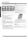
■ L’appareil doit être alimenté par un circuit de 120 V CA seulement,
60 Hz, 15 ampères, protégé par fusible.
■ If the house has aluminum wiring, follow the procedure below:
1. Raccorder une section de câble en cuivre massif aux conducteurs en
queue de cochon.
2. Connecter le câblage en aluminium à la section ajoutée de câblage
en cuivre en utilisant des connecteurs et/ou des outils spécialement
conçus et homologués UL pour xer le cuivre à l’aluminium.
■ Suivre la procédure recommandée par le fabricant de connecteurs
électriques. Les raccordements aluminium/ cuivre doivent
satisfaire aux prescriptions des codes locaux et de l’industrie, et être
conformes aux pratiques de câblage reconnues.
■ Le calibre des conducteurs et les connexions doivent être compatibles
avec les caractéristiques électriques de l’appareil spéciées sur la
plaque signalétique. La plaque signalétique de l’appareil est située
derrière le ltre, sur la paroi arrière de la hotte.
■ Le calibre des conducteurs doit être conforme aux exigences du
National Electrical Code, de la plus récente édition de la norme ANSI/
NFPA 70 ou des normes CSA C22. 1-94, Code canadien de
l’électricité, partie 1 et C22.2 n° 0-M91 (édition la plus récente) et de
tous les codes et règlements en vigueur.
Exigences Concernant l’évacuation
• Le circuit d’évacuation doit décharger l’air à l’extérieur.
• Ne pas terminer le circuit d’évacuation dans un grenier ou dans un
autre espace fermé.
• Ne pas utiliser une bouche de décharge murale de 4” (10,2 cm)
normalement utilisée pour un équipement de buanderie).
• Utiliser uniquement des conduits métalliques. Des conduits en métal
rigide sont recommandés. Ne pas utiliser de conduit de plastique ou
en aluminium.
• La longueur du circuit d’évacuation et le nombre de coudes doivent
être réduits au minimum pour fournir la meilleure performance.
Pour un fonctionnement efcace et silencieux:
• Ne pas utiliser plus de trois coudes à 90°.
• Veiller à ce qu’il y ait une section droite de conduit de 24” (61 cm) ou
plus entre les coudes, si on doit utiliser plus d’un raccord coudé.
• Ne pas connecter 2 coudes ensemble.
• Au niveau de chaque jointure du circuit d’évacuation, assurer
l’étanchéité avec les brides de serrage.
• Le circuit d’évacuation doit comporter un clapet antireux.
• Si la bouche de décharge murale ou par le toit comporte un clapet, ne
pas utiliser le clapet fourni avec la hotte d’extraction.
• Assurer l’étanchéité avec un composé de calfeutrage autour de la
bouche de décharge à l’extérieur (mur ou toit).
• La taille du conduit doit être uniforme.
Méthodes d’évacuation
Pour utiliser la sortie d’air supérieure de votre hotte, vous aurez besoin
d’un conduit d’évacuation rond de 6 “(15,2 cm). Pour utiliser la sortie
arrière, un conduit d’évacuation rectangulaire de 8,25 x 25,4 cm (3
1
⁄4 “x
10”) est requis. Aucun de ces conduits n’est inclus dans cette campagne
et doit être acheté séparément.
REMARQUE
On déconseille l’emploi de conduit exible. Un conduit exible peut
causer une rétropression et des turbulences de l’air, ce qui réduit consi-
dérablement la performance. La sortie à l’extérieur du circuit d’évacuation
peut se faire à travers le toit ou à travers un mur. Pour la sortie à travers
un mur, on doit employer un raccord coudé (90°).
Hauteur de Montage
Sélectionner une hauteur de montage comprise entre un minimum de
24“ (61 cm) pour une surface de cuisson électrique, un minimum de
27“ (68,5 cm) pour une surface de cuisson au gaz et un maximum sug-
géré de 36” (91,4 cm) entre le dessus de la cuisinière et le bas de la
hotte.
Exigences d’Installation
Exigences d’Installation

20 Français
Outils et Pièces
Enlever l’emballage
ATTENTION
Enlever délicatement le carton. Porter des gants pour se protéger
des bords coupants.
AVERTISSEMENT
Enlever le lm de protection recouvrant le produit avant de
commencer l’opération.
Outils et pièces
• Hotte avec ventilateur et lampes DEL
• Kit quincaillerie comprenant:
Pièce Quantité Pièce Quantité
5x45 mm
4
5.4x75 mm
4
4.5x13 mm
4
10 x 60 mm
4
3.5x9.5 mm
2
Adaptateur Torx 10
1
4.2x8 mm
7
Adaptateur Torx 20
1
Transition rond de 6”
(15.2 cm)
1
Transition rectangulaire
de 3
1
⁄4” x 10” (8.3 x 25.4
cm)
1
Support de xation de
moteur par l’arrière
1
Outils nécessaires
• Niveau
• Perceuse avec forets de 1¼” (3.2 cm),
1
⁄8” (3.2 mm), y
1
⁄16” (4,8 mm)
• Crayon
• Pince à dénuder ou couteau utilitaire
• Mètre-ruban ou règle
• Pince
• Pistolet à calfeutrage et composé de calfeutrage résistant aux
intempéries
• Brides de conduit
• Scie sauteuse ou scie à guichet
• Tournevis à lame plate
• Cisaille de ferblantier
• Tournevis Phillips (Pozidrive) et tournevis Torx 20
Pièces nécessaires
• Câble d’alimentation électrique du domicile
• Serre-câble de
1
⁄2” (12,7 mm) (homologation UL ou CSA)
• 3 connecteurs de ls homologués UL
• 1 bouche de décharge (décharge à travers le mur ou à travers le toit)
• Circuit d’évacuation métallique
Exigences d’Installation
Exigences d’Installation
Pour une installation sans conduit (recyclage)
S’il n’est pas possible d’évacuer les fumées et les vapeurs de cuisson
vers l’extérieur, la hotte peut être utilisée dans la version sans conduit
(recyclage) utilisant un ltre à charbon et une grille en plastique. La
fumée et les vapeurs sont recyclées à travers un ltre à charbon.
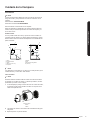
Décharge à travers le toit Évacuation par le mur
A
C
B
D
A
C
B
D
A. Conduit de 6” (15,2 cm)
B. Transition ronde de 6” (15,2 cm)
C. Bouche de décharge sur toit
D. Hauteur de montage
A. Conduit de dia. 6” (15,2 cm) + coude 90º
B. Transition rectangulaire de
3
1
⁄4” x 10” (8,3 x 25,4 cm)
C. Bouche de décharge murale
D. Hauteur de montage
Recyclage à travers le toit du cabinet Recyclage à travers le cabinet
A
B
A
B
A. Grille de recyclage en plastique
B. Conduit de 6” (15,2 cm)
A. Grille de recyclage en plastique
B. Conduit de dia. 6” (15,2 cm) + coude 90º
La page charge ...
La page charge ...
La page charge ...
La page charge ...
La page charge ...
La page charge ...
La page charge ...
La page charge ...
La page charge ...
La page charge ...
La page charge ...
La page charge ...
La page charge ...
La page charge ...
La page charge ...
La page charge ...
La page charge ...
La page charge ...
La page charge ...
La page charge ...
La page charge ...
La page charge ...
La page charge ...
La page charge ...
La page charge ...
La page charge ...
La page charge ...
La page charge ...
-
 1
1
-
 2
2
-
 3
3
-
 4
4
-
 5
5
-
 6
6
-
 7
7
-
 8
8
-
 9
9
-
 10
10
-
 11
11
-
 12
12
-
 13
13
-
 14
14
-
 15
15
-
 16
16
-
 17
17
-
 18
18
-
 19
19
-
 20
20
-
 21
21
-
 22
22
-
 23
23
-
 24
24
-
 25
25
-
 26
26
-
 27
27
-
 28
28
-
 29
29
-
 30
30
-
 31
31
-
 32
32
-
 33
33
-
 34
34
-
 35
35
-
 36
36
-
 37
37
-
 38
38
-
 39
39
-
 40
40
-
 41
41
-
 42
42
-
 43
43
-
 44
44
-
 45
45
-
 46
46
-
 47
47
-
 48
48


Samsung NK30N7000US/AA Manuel utilisateur
- Taper
- Manuel utilisateur
dans d''autres langues
- English: Samsung NK30N7000US/AA User manual
- español: Samsung NK30N7000US/AA Manual de usuario
Documents connexes
Autres documents
-
ELICA EMD536S3 Guide d'installation
-
Whirlpool WVU57UC0FS0 Le manuel du propriétaire
-
-
 arietta ASG436SSA Mode d'emploi
-
-
-
Thermador HMDW36WS Mode d'emploi
-
-
-
Broan 360NDK Guide d'installation
